EP1408202A2 - Brennkraftmaschine versehen mit einem Prozessor und Zylindern, wovon jeder minimal zwei elektromagnetische Einlassventile enthält - Google Patents
Brennkraftmaschine versehen mit einem Prozessor und Zylindern, wovon jeder minimal zwei elektromagnetische Einlassventile enthält Download PDFInfo
- Publication number
- EP1408202A2 EP1408202A2 EP03300071A EP03300071A EP1408202A2 EP 1408202 A2 EP1408202 A2 EP 1408202A2 EP 03300071 A EP03300071 A EP 03300071A EP 03300071 A EP03300071 A EP 03300071A EP 1408202 A2 EP1408202 A2 EP 1408202A2
- Authority
- EP
- European Patent Office
- Prior art keywords
- mode
- cylinder
- torque
- engine
- valves
- Prior art date
- Legal status (The legal status is an assumption and is not a legal conclusion. Google has not performed a legal analysis and makes no representation as to the accuracy of the status listed.)
- Withdrawn
Links
- 238000002485 combustion reaction Methods 0.000 title claims abstract description 16
- 238000012360 testing method Methods 0.000 claims description 58
- 230000008859 change Effects 0.000 claims description 37
- 239000000446 fuel Substances 0.000 claims description 15
- 230000007704 transition Effects 0.000 claims description 10
- 239000007789 gas Substances 0.000 claims description 8
- 239000000203 mixture Substances 0.000 claims description 7
- 230000003213 activating effect Effects 0.000 claims description 6
- 239000002826 coolant Substances 0.000 claims description 2
- 230000009849 deactivation Effects 0.000 description 25
- 230000001960 triggered effect Effects 0.000 description 23
- 230000004913 activation Effects 0.000 description 20
- 238000001994 activation Methods 0.000 description 20
- 230000007423 decrease Effects 0.000 description 15
- 238000010586 diagram Methods 0.000 description 12
- 230000006870 function Effects 0.000 description 12
- 230000001133 acceleration Effects 0.000 description 4
- 230000009471 action Effects 0.000 description 4
- 230000009467 reduction Effects 0.000 description 4
- 230000004044 response Effects 0.000 description 4
- 241001080024 Telles Species 0.000 description 3
- 230000007420 reactivation Effects 0.000 description 3
- 230000006835 compression Effects 0.000 description 2
- 238000007906 compression Methods 0.000 description 2
- 238000001914 filtration Methods 0.000 description 2
- 238000002347 injection Methods 0.000 description 2
- 239000007924 injection Substances 0.000 description 2
- 230000007257 malfunction Effects 0.000 description 2
- 238000000034 method Methods 0.000 description 2
- 230000006641 stabilisation Effects 0.000 description 2
- 238000011105 stabilization Methods 0.000 description 2
- 241000287107 Passer Species 0.000 description 1
- 241000897276 Termes Species 0.000 description 1
- 240000008042 Zea mays Species 0.000 description 1
- 230000008901 benefit Effects 0.000 description 1
- 239000000567 combustion gas Substances 0.000 description 1
- 230000000295 complement effect Effects 0.000 description 1
- 238000001816 cooling Methods 0.000 description 1
- 239000000498 cooling water Substances 0.000 description 1
- 230000003247 decreasing effect Effects 0.000 description 1
- 230000001934 delay Effects 0.000 description 1
- 235000021183 entrée Nutrition 0.000 description 1
- 230000002349 favourable effect Effects 0.000 description 1
- 238000011049 filling Methods 0.000 description 1
- 239000003546 flue gas Substances 0.000 description 1
- 239000012530 fluid Substances 0.000 description 1
- 238000011990 functional testing Methods 0.000 description 1
- 238000011068 loading method Methods 0.000 description 1
- 238000012423 maintenance Methods 0.000 description 1
- 238000013507 mapping Methods 0.000 description 1
- 238000005259 measurement Methods 0.000 description 1
- 238000012986 modification Methods 0.000 description 1
- 230000004048 modification Effects 0.000 description 1
- 230000010355 oscillation Effects 0.000 description 1
- 229920006395 saturated elastomer Polymers 0.000 description 1
- 238000000926 separation method Methods 0.000 description 1
- 230000008054 signal transmission Effects 0.000 description 1
Images








Classifications
-
- F—MECHANICAL ENGINEERING; LIGHTING; HEATING; WEAPONS; BLASTING
- F02—COMBUSTION ENGINES; HOT-GAS OR COMBUSTION-PRODUCT ENGINE PLANTS
- F02D—CONTROLLING COMBUSTION ENGINES
- F02D13/00—Controlling the engine output power by varying inlet or exhaust valve operating characteristics, e.g. timing
- F02D13/02—Controlling the engine output power by varying inlet or exhaust valve operating characteristics, e.g. timing during engine operation
- F02D13/0257—Independent control of two or more intake or exhaust valves respectively, i.e. one of two intake valves remains closed or is opened partially while the other is fully opened
-
- F—MECHANICAL ENGINEERING; LIGHTING; HEATING; WEAPONS; BLASTING
- F01—MACHINES OR ENGINES IN GENERAL; ENGINE PLANTS IN GENERAL; STEAM ENGINES
- F01L—CYCLICALLY OPERATING VALVES FOR MACHINES OR ENGINES
- F01L13/00—Modifications of valve-gear to facilitate reversing, braking, starting, changing compression ratio, or other specific operations
- F01L13/0005—Deactivating valves
-
- F—MECHANICAL ENGINEERING; LIGHTING; HEATING; WEAPONS; BLASTING
- F01—MACHINES OR ENGINES IN GENERAL; ENGINE PLANTS IN GENERAL; STEAM ENGINES
- F01L—CYCLICALLY OPERATING VALVES FOR MACHINES OR ENGINES
- F01L9/00—Valve-gear or valve arrangements actuated non-mechanically
- F01L9/20—Valve-gear or valve arrangements actuated non-mechanically by electric means
-
- Y—GENERAL TAGGING OF NEW TECHNOLOGICAL DEVELOPMENTS; GENERAL TAGGING OF CROSS-SECTIONAL TECHNOLOGIES SPANNING OVER SEVERAL SECTIONS OF THE IPC; TECHNICAL SUBJECTS COVERED BY FORMER USPC CROSS-REFERENCE ART COLLECTIONS [XRACs] AND DIGESTS
- Y02—TECHNOLOGIES OR APPLICATIONS FOR MITIGATION OR ADAPTATION AGAINST CLIMATE CHANGE
- Y02T—CLIMATE CHANGE MITIGATION TECHNOLOGIES RELATED TO TRANSPORTATION
- Y02T10/00—Road transport of goods or passengers
- Y02T10/10—Internal combustion engine [ICE] based vehicles
- Y02T10/12—Improving ICE efficiencies
Definitions
- the present invention relates to a motor with internal combustion equipped with a processor and actuators electromechanical valve control.
- a cylinder says “four time “performs a cycle including a step of admitting a fuel mixture in a combustion chamber, a step of compression of this mixture until its combustion, a step of expansion of the combustion gases and an exhaust step for these chamber gas.
- gas exchanges between the interior and exterior of the combustion chamber are controlled by intake or exhaust valves, such valves being called “open” (“closed”) when they allow (prevent) gas exchanges between the interior and the outside of the combustion chamber.
- Opening or closing a valve is determined by the operation of the cylinder. So during a intake stage, the intake valve (s) is (are) open, the intake and exhaust valves are closed during the compression and expansion stages while, during the exhaust stage, the exhaust valve (s) is (are) open.
- the open or closed valve positions are controlled either mechanically or electromechanical as described below:
- valve In the first case (mechanical control) the valve is mechanically secured to the piston and its position is depending on the position of the piston in the combustion chamber.
- the valve is controlled by a device or actuator electromechanical including for example springs combined with electromagnets to control the opening or closing of this valve.
- FIG. 1 represents such an actuator controlling a valve 10 shown in the closed position, that is to say applied against its seat 12. In this position, the interior 14 of the combustion chamber of cylinder 15 is isolated from the outside 17 of this cylinder.
- the valve 10 is kept closed or open thanks to the electromechanical actuator comprising springs 16 and 18 and electromagnets 20 and 22.
- the electromagnet 20, the most away from the combustion chamber, is intended to attract a plate 24 to apply it against a face 26 of the circuit magnetic of this electromagnet 20.
- the valve 10 is then closed by the action of the spring 16 on the rod 27.
- the second electromagnet 22 controls the valve 10 in the open position.
- the coil of this solenoid 22 is activated after deactivation of the solenoid coil the electromagnet 20.
- the plate 24 then separates from the face 26 of the magnetic circuit of the electromagnet 20, this separation being facilitated by the action of the spring 18.
- the electromagnet 22 When the electromagnet 22 is activated, it attracts the plate 24 towards a face of its magnetic circuit. This attraction being greater than the action of the spring 16, it opens the valve 10 by the action of a rod 25, integral with the plate 24, on the rod 27 valve 10.
- an engine when an engine is fitted with cylinders comprising a plurality of intake valves which can be individually controlled, we can selectively maintain one or more of these intake valves closed for order an engine operating mode. For example, when these cylinders are fitted with two intake valves, you can use or activate one or two intake valves per cylinder, the engine then operating in a mode known as one or two intake valves per cylinder.
- intake valves are performing different functions such as admission control control of an air and fuel intake, we can selectively keep closed the valves performing a type of admission.
- the present invention results from the observation that parameters external to engine operation, relative to a driving mode of the vehicle, must be considered for control the number and / or type of valves kept active in a cylinder. For example, keep active the set of engine intake valves when a sporty driving with high acceleration is practiced so as to admit a quantity into the cylinder maximum of fuel mixture in the cylinder and get thus rapid accelerations. Conversely, when low accelerations are required, a number should be used reduced intake valves per cylinder so that focus on saving fuel.
- the present invention relates to a internal combustion engine comprising a processor and cylinders with at least two intake valves controlled by electromechanical actuators, characterized in that the processor comprises means for receiving information relating to the operation of the engine and information relating to the driving of the vehicle, and the means to control actuators to change the number and / or the type of active intake valves per cylinder, one valve disabled being maintained in a closed position.
- the processor controlling the number and / or the type of active intake valves per cylinder using of electromechanical actuators can take into account the engine and driving information to perform this check.
- deactivation and transition between different modes of operation can be developed and applied by simple programming of the processor to prevent possible malfunctions of the engine during mode changes. This programming can be modified by loading new programs.
- the processor includes means for receiving information about the engine which relate to at least one of the following parameters: of the engine, the torque commanded from the engine, the temperature of the coolant, composition and / or temperature exhaust gases, the clutch of a gear, and / or the amount of fuel injected into the cylinders.
- the processor may also include means for receive information about driving the vehicle which relate to at least one of the following parameters: the speed of the vehicle, the trajectory of the vehicle, a type of driving of the vehicle.
- the processor comprises, in one example, means for modifying the torque commanded (C gross ) by the driver of the vehicle into a filtered couple (C filter ) attenuating the variations in this commanded torque (C gross ) and for determining the number and / or the type of active intake valves per cylinder depending on this filtered torque.
- the processor comprises, in one example, means for control at least two of the following modes: an activating mode all intake valves, a mode that activates only the (or) valve (s) controlling a fuel intake, a mode activating only the valve (s) controlling a air intake, a mode deactivating all valves intake.
- the processor includes means to activate and / or deactivate, when changing mode of the number and / or type of active valves per cylinder, the intake valves of each cylinder considered successively.
- the processor may include means for controlling successively a change in mode of the number and / or type of active intake valves to a first cylinder of a first pair, to the second cylinder of this first pair, to a first cylinder from a second pair then to a second cylinder of the second pair.
- the processor includes means for determining an operating mode relative to the mode for lifting the active valves.
- the processor has means for using a lifting mode conventional intake valves, comprising a control and a valve close command, or a ballistic lifting mode, comprising a single command opening or closing the intake valve.
- the processor includes means so that the change from one mode to another mode takes place when the filtered pair (C filter ) reaches a test pair (C 40 "(min), C 40 ' (min) C 40 "(max); C 40 '(max)) and that the variation ( ⁇ C gross ) of torque (C gross ) commanded is greater than a maximum positive threshold (DC max ; DC' max ) of variation when the variation is positive, or less than a minimum negative variation threshold (DC " min ) when the variation is negative.
- the processor may include means for controlling the classic mode without transition from a ballistic mode.
- the processor comprises, according to an embodiment, means for successively controlling the ballistic mode from a classical mode to valves of a first cylinder of a first pair, to valves of the second cylinder of this first pair, to valves of a first cylinder of a second pair and to valves of the second cylinder of the second pair.
- a control unit 30 controls the actuators electromechanical engine valves (not shown) of in order to optimize the consumption of the latter by modifying the number of active cylinders in the engine, i.e. generating engine torque.
- This unit 30 is also used to filter the gross torque ordered by the driver of the vehicle, hereinafter referred to as gross C, into a filtered torque, hereinafter referred to as C filter , so as to provide limiting driving pleasure, for example , excessively sudden torque variations.
- this unit 30 receives information CV relating to the driving of the vehicle, such as the driving mode or the speed of the vehicle, and information relating to the operation of the engine, namely its speed R, the gross torque C controlled by the driver, the temperature T of the cooling system, the quantity Q of fuel injected into each cylinder and the average richness G of the exhaust gases.
- Unit 30 then controls the actuators electromechanical engine valves in accordance with a previously defined mapping (for example empirical) determining the number of active cylinders which, in based on this information, optimize the consumption of engine fuel.
- a previously defined mapping for example empirical
- these electromechanical actuator controls can disrupt the engine operation. For example, a failure to synchronization in the operation of the different cylinders can cause vibration of the elements engine (cylinder, crankshaft, etc.) and / or discontinuities in the torque supplied by the engine. In addition, deactivation of cylinder (s) can cause an increase in the response to a request for acceleration, which would be dangerous, for example when overtaking.
- the unit 30 is informed of the parameters already indicated, namely the gross torque C commanded from the engine, the speed R of the latter, the temperature T of the cooling water, the quantity Q of fuel injected into the cylinder, CV information specific to driving the vehicle and the average richness G of the exhaust gases.
- the torque C i to be delivered by each cylinder (i) kept active is determined (block 36) so as to avoid discontinuities in the torque delivered by the motor when changing modes.
- this data is transmitted (block 37), then the number and type of active intake valves (block 38) and the conventional or ballistic lifting mode used for each active cylinder are determined. each valve kept active (block 39) in the cylinder i considered. These determinations are made each time the motor control function is called, that is to say each time the engine is turned. More precisely, the various setpoints are determined once per cycle of each cylinder. As the engine has four cylinders and a cycle lasts two engine revolutions, the determination for each cylinder therefore corresponds to a duration of half an engine revolution.
- the loop B shown in Figure 2 represents the setting constantly updating the determinations of the various modes.
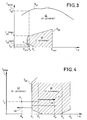
- Curves G 40 and G 42 delimit, respectively, zones 40 and 42 of operation of the engine tested in two-cylinder mode (zone 40) or in four-cylinder mode (zone 42).
- the engine tested can deliver a torque C F at a speed R F if the point F of operation of abscissa C F and ordinate R F is located in a zone corresponding to this mode.
- the operating point F represented in FIG. 3 is located in zone 42 and only the four-cylinder mode delivers the torque C F and the required speed R F.
- the limits of the two-cylinder mode and of the four-cylinder mode are determined in terms of engine speed and torque.
- the speed R is lower than the minimum speed R min of the two-cylinder mode, or higher than the maximum speed R max of this mode with two cylinders, only the four-cylinder mode can be used by the engine.
- the four-cylinder mode is limited to a maximum torque C 42 while the two-cylinder mode is limited to a maximum torque C 40 (max) or minimum C 40 (min) .
- each operating mode can be established for a determined torque. For example, a torque C F being fixed for the engine, the two-cylinder mode has a minimum speed R 1 below which the two-cylinder mode cannot be used, as well as a maximum speed R max beyond which the two cylinder mode cannot be used.
- the change in the number of active cylinders uses two stabilization strategies considering, respectively, a change due to a variation of the speed R or a change due to a variation of the torque C filter controlled by the engine.
- a first threshold speed R 1 for triggering the four-cylinder mode and a second threshold speed R 1 'for triggering the two-cylinder mode, distinct from the first, are used to define a stability range between these thresholds as shown in FIG. 4, which is an enlargement of a part of FIG. 3 on which the zones 42 (four-cylinder mode) and 40 (two-cylinder mode) are represented, as well as the curve G 40 .
- An operating point F has also been shown located in zone 42, the engine then being in four-cylinder mode.
- the two-cylinder mode is only established when the speed R reaches a threshold R ' 1 for triggering the two-cylinder mode higher than the speed R 1 of the curve G 40 previously determined ( Figure 3).
- the four-cylinder mode is imposed even though the two-cylinder mode would be more economical.
- the example described above relates to a change from four-cylinder mode to a two-cylinder mode triggered by an increase in speed, and to a change from two-cylinder mode to the four-cylinder mode triggered by decrease in speed .
- the transition from a four-cylinder mode to a two-cylinder mode triggered by a reduction in engine speed, and the transition from a two-cylinder mode to a four-cylinder mode triggered by an increase in regime uses a threshold R 2 (FIG. 4) for triggering the four-cylinder mode and a threshold R ' 2 for triggering the two-cylinder mode so as to define a range [R' 2 ; R 2 ] of stability.
- the stabilization strategy also takes into account the value and variations of the gross torque C controlled by the user as described below. below using figures 5, 6a, 6b and 6c.
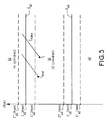
- FIG. 5 is represented a part of FIG. 3 comprising the maximum couples C 40 (max) and minimum C 40 (min) of the two-cylinder mode coming from the curve G 40 (FIG. 3), these couples C 40 (max ) and C 40 (min) being used (and named later) as trigger thresholds. Variations of the filtered torque (curve C filter) and crude (Crude torque C) are also shown.
- the engine operates in a two-cylinder mode, its operating point F 1 corresponding to a torque below the trigger threshold C 40 .
- the torque C filter increases and reaches a threshold C '40 (max) lower test torque C 40 (max)
- the torque value C Raw is considered to determine whether the four-cylinder mode should be triggered.
- Such a threshold C '40 (max) test is used to account for changes in gross torque C and trigger a mode change before the torque C filter reaches the threshold C 40 (max) for tripping. Such use makes it possible to consider situations such as when a large increase in gross torque C is required to perform an overshoot and the engine operates in two-cylinder mode.
- the four-cylinder mode should be triggered before the threshold C 40 (max) for triggering this mode is reached by the required torque C filter so as to allow the required torque increase.
- the filter C and gross C couples vary greatly, the engine operating in a four-cylinder mode, and that, the filter C torque being located in a two-cylinder operating zone, the gross C torque crosses this zone and is located in a four-cylinder zone, the four-cylinder mode should be maintained despite the presence of the torque C filter in the two-cylinder zone.
- a first mode should be triggered when, with the engine operating in a second mode, the required torque C gross varies greatly so as to anticipate the triggering of the first mode.
- the first case (a) and the third case (c) are similar since a gross increase ⁇ C of the torque is considered.
- the motor changes mode if, the filter torque C having reached a test threshold, the torque variation is greater than the maximum threshold considered.
- gross ⁇ C is positive as well as the maximum and minimum thresholds considered.
- the increase in gross torque ⁇ C is less than the maximum threshold, the value of this increase is compared with a minimum threshold such that, if this increase in gross ⁇ C is less than the minimum threshold, it is considered to be small and no mode change n 'is done.
- the second case (b) and the fourth case (d) are similar in that a crude .DELTA.C torque reduction crude C being considered, the motor adjustment mode if the filter torque C reaching a test threshold, the variation torque is less than a minimum threshold considered.
- gross ⁇ C is negative as well as the maximum and minimum thresholds.
- a variation in torque below a threshold means that in absolute value this variation is greater than the absolute value of the threshold.
- this variation is compared to a maximum threshold such that, if this gross decrease ⁇ C is greater than the minimum threshold, it is considered to be small and no mode change is made.
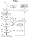
- This test 50 uses a variable E commut , whose value varies between zero and one, and is such that a command 52 for applying the four-cylinder mode is transmitted to the engine if a test (block 53) detects that this variable E commut is equal to one. Otherwise, the two-cylinder mode is maintained.
- the central unit tests (block 54) the operating conditions of the engine and vehicle. Indeed, in the embodiment described, the mode four cylinder is immediately imposed when the engine operates in so-called “winnowed” mode (ie when the engine air filling is mechanically controlled by a throttle), when the engine is disengaged, no gearbox not engaged, when the engine is running idle and / or when the driver does not press Accelerate the
- the central unit also tests whether the torque C filter has reached the threshold C '40 (max) test considered in this case. If this is not the case, we wait (block 55) for a motor half-turn before restarting the test (block 54).
- variable E commut is maintained at its value determined at the end of this previous test.
- the value of the gross torque C is compared to the tripping torque C 40 (max) (block 58). If the gross torque C is greater than the torque C 40 (max), the four-cylinder mode is triggered by the emission of a signal 56 1 causing the variation (block 59) of the variable E commut from the value 0 to the value 1.
- the controller 56 transmits a signal 0 to assess gross .DELTA.C variation in torque C relative to raw DC maximum threshold values max and min minimum DC used in this test .
- the difference between t and t-1 corresponds to the time elapsed between two successive calls to the engine control function, that is to say to the time elapsed during an engine U-turn (this time therefore depends on the engine speed).
- a signal 60 1 causes the variation of the variable E commut to the value 1, the four-cylinder mode being imposed on the engine. This test is represented by block 60.
- this gross ⁇ C variation is compared to the minimum DC min threshold (block 62).
- this gross ⁇ C variation is not taken into account and the variable E commutates at zero (block 63) while a new calculation cycle is carried out.
- E commut When gross ⁇ C is greater than DC min , E commut is changed to E commut + ⁇ , ⁇ being constant, this new value of E commut being memorized after having checked (block 53) that it did not reach one, in which case the four-cylinder mode is triggered.
- cycles 66 (figure 6b) and 80 (figure 6c) of tests, analogous to cycle 50, are carried out by unit 30 for control the possible activation of the two-cylinder mode, the cycle 66, respectively cycle 80, being considered when the triggering of a two-cylinder mode is due to a increase in torque, respectively a decrease in couple.
- Figure 6b is a flow diagram which corresponds to case c), that is to say the transition from a mode to four cylinders to a two cylinder mode when the torque increases.
- Ring 66 test comprises already described operations such as the test (block 54) of vehicle operating conditions and zero setting of the variable E switched (block 56) if the test line (C '40 (min) ) considered is crossed during the execution of this test.
- a test compares the gross torque C requested to the threshold C 40 (min) for triggering the two-cylinder mode. If the gross torque C is greater than the trigger threshold C 40 (min), the two-cylinder mode is established.
- this increase may cause the four-cylinder mode to be triggered soon after it is deactivated.
- this increase in torque can be such that the engine operating point will quickly pass through zone 40 of the two-cylinder mode and again be in zone 42 of the four-cylinder mode. In this case, the triggering of the two-cylinder mode should be avoided.
- the triggering torque C 40 (max) is used to carry out a test (block 70) comparing the gross torque C to this torque C 40 (max). If the latter is less than the gross torque C, it is considered that the gross torque C increases sufficiently large so that the triggering of the two-cylinder mode is prevented by maintaining (block 72) of E commut at zero. On the other hand, if C gross is less than C 40 (max), the mode change takes place by holding (block 74) of E commut at 1.
- the variation ⁇ C gross of this torque is compared with two threshold values DC ' max (block 76) maximum and DC' min minimum. Thus, if the gross variation ⁇ C is greater than DC ' max , the two-cylinder mode is triggered (block 74).
- FIG. 6c a cycle 80 of tests relating to a change from the four-cylinder mode to the two-cylinder mode due to a reduction in the torque demanded.
- This cycle includes the operations 54 and 56 already described, the torque C 40 "(max) being used as the test torque.
- a test 82 compares the gross torque C with torque C 40 (max) for triggering the two-cylinder mode as described in Figure 3.
- a test compares the value of the gross torque C with respect to the threshold torque C 40 (min ) to determine if the gross torque C does not decrease rapidly, in which case a triggering of the two-cylinder mode would be quickly followed by a triggering of the four-cylinder mode.
- tests 88 and 90 compare the variation ⁇ C gross of the requested torque with respect to two threshold values DC ⁇ max maximum and DC '' minimum min , so to activate the activation of the two-cylinder mode if this gross variation ⁇ C is less than DC '' max (block 88) or, if necessary, modify the value of E commut if this variation is less than DC '' min .
- FIGS. 7a, 7b and 7c are shown examples of variations in gross torque C and filter C to which the test cycles described above are applied.
- FIG. 7a is formed from three diagrams 7a.1, 7a.2 and 7a.3, diagram 7a.1 representing an example of variation of the pairs C gross and C filter (on the ordinate, in Nm) as a function of an axis chronological (on the abscissa).
- the working engine according to a two-cylinder mode when C filter exceeds the torque threshold C '40 (max) test at a time t 0, the torque crude C being between the torque C' 40 (max ) and C 40 (max) and its variation ⁇ C gross being between DC max and DC min (diagram 7a.2).
- variable E commut increases steadily as a function of time of an index ⁇ (FIG. 8) in accordance with the operation represented by block 64 of test 50 (FIG. 6a).
- Figure 7b is considered a second example of changes in crude couples C and C filter (7B.1 diagram) such that at time t 0 where C filter has a torque value greater than the threshold torque C '40 (max ), the gross torque C increases, with a gross variation ⁇ C between DC max and DC min , up to an instant t 1 . Thereafter, the gross torque C stabilizes, the variation ⁇ C gross becoming zero.
- variable E commut increases by a value ⁇ from this instant t 0 until reaching the value of 1 at an instant t 3 when the four-cylinder mode is triggered.
- C filter reaches the torque threshold torque C '40 (max) at the instant t 1 and the threshold torque C 40 (max) at an instant t 3 .
- the gross torque C increases with a gross variation ⁇ C between DC max and DC min so that the variable E commut increases with a constant step of ⁇ from from this instant t 1 .
- the gross torque C reaches the threshold torque C 40 (max) so that the variable E commut is immediately set to 1 (block 59 of FIG. 6a), the four-cylinder mode being triggered.
- FIG. 7d is shown a last example of variation of the pairs C gross and C filter , this example using the test cycle described with the aid of FIG. 6b.
- the filter torque C reaches the torque C 40 (min) at an instant t 1 and the torque C 40 (max) at an instant t 2 .
- the variation of the gross torque C is such that at time t 1 , the gross torque C is greater than the tripping torque C 40 (max).
- variable E commut is maintained at zero and the four-cylinder mode is maintained throughout the interval [t 1 ; t 2 ] in accordance with test 6b (block 70).
- cylinders 2 and 3 inactive consume energy to maintain their movement.
- the torques C 1 and C 4 supplied by the active cylinders 1 and 4 must increase so as to compensate, first of all , the decreases in the engine torques of cylinders 2 and 3, then, in a second step, the frictional couples -2C consumed by these cylinders 2 and 3.
- Switching from one mode to another can lead to unwanted vibrations or oscillations of the vehicle.
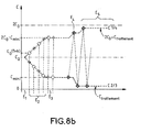
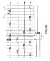
- changing the mode to four cylinders to two cylinder mode is performed progressively as explained using FIGS. 8a and 8b and from table 1 below.
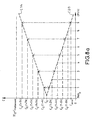
- FIG. 8a shows the evolution of the couples C 1/4, supplied by the cylinders 1 and 4, kept active, and C 2/3 , supplied by the two cylinders 2 and 3 deactivated.
- the value C of these torques in Nm is plotted on the ordinate and the progress of deactivation is shown on the abscissa, this progress being represented by the number of top dead centers (TDC) made by the cylinders from a first TDC 0 for which the two-cylinder mode is triggered, this TDC 0 being performed by a cylinder kept inactive in this example.
- TDC top dead centers
- a factor k of variation is used which makes it possible to increase the torque C 1/4 so as to compensate for the decrease in the torque C 2/3 .
- the torque C 1/4 becomes equal to C filter (1 + nk)
- the torque C 2/3 becomes equal to C filter (1 - nk)
- n being the number of cycles performed by the engine from the decision to change modes and until the change of mode.
- the number n of cycles depends on the required mode of evolution, that is to say a more or less rapid evolution of the torques provided by the cylinders, and a minimum value C mini of the torque which can be reached by the cylinders 2 and 3, limit value from which combustion no longer occurs in the cylinder.
- the first stage (stage 1: E 1 ) of deactivation of cylinders 2 and 3 corresponds to an operation of the engine in four-cylinder mode, the torque C 1/4 and the torque C 2/3 being equal to the average torque C filter per cylinder delivered by the engine.
- step 2 E 2
- the torque C 1/4 delivered by each of cylinders 1 and 4 increases linearly so as to tend towards the desired final torque 2C filter + C friction .
- the number of iterations necessary for the torque C 1/4 supplied by cylinders 1 and 4 to reach the value of 2C filter -C minimum and for cylinders 2 and 3 to reach the torque C minimum depends on the engine speed of the torques C mini , C filter and the value of k determined beforehand. In other words, the number of iterations is not predictable.
- step 3: E 3 the cylinders 1 and 4 are saturated with the 2xC filter- mini couple and the cylinders 2 and 3 with the C mini torque, parallel to the transmission of a signal triggering the closing of the valves of cylinders 2 and 3.
- the deactivation of cylinders 2 and 3 starts at one time such that cylinder deactivation is performed from so that flue gases are kept in the deactivated cylinders, that is to say that the actuator control lead times electrohydraulics controlling the exhaust valves.
- This actuator response time i.e. solenoid valves, oil circuit and stops, is determined empirically. It depends on the speed and the pressure and / or the oil temperature.
- the number of half-turns of the corresponding motor response time is evaluated with each call to the function of the speed and oil pressure or temperature. If this time corresponds to two engine U-turns deactivation begins during a TDC of a cylinder kept active. If this time again corresponds, for example, to 3 engine U-turns the solenoid valve control starts at TDC of a cylinder deactivatable.
- step 4 E 4
- the cylinders 1 and 4 provide an intermediate torque equal to 2C filter +1/2 (C friction -C minimum ) while at the end of deactivation (step 5: E 5 ), this torque is maintained at 2C filter + C friction , the torque supplied by each cylinder 2 and 3 being equal to - C friction .
- a delay ⁇ t 'of pressurizing the pushers is also represented along the chronological axis of abscissa.
- step 1 ′ the engine operates in a two-cylinder mode such that the active cylinders 1 and 4 provide a torque C 1/4 equal to 2xC filter + C friction , while the cylinders 2 and 3 provide a negative torque equal to C friction .
- step 2 ' a command to reactivate cylinders 2 'and 3'.
- This order is transmitted to the electrohydraulic device controlling cylinder exhaust valves deactivated if the number of cylinder, the reactivation time of these control means and engine speed are compatible with the execution time of this command as described later. Otherwise, the command is transmitted to the next top dead center. During this waiting phase, the effective reactivation of the exhausts is not performed.
- step 3 the couple C 2/3 transmits a minimum torque C which then increases (step 4) so as to tend towards C filter from iterations similar to those previously described for deactivation of cylinders.
- these complementary modes are chosen according to a given order such that we determine the number of active cylinders and then the active valves per cylinder and ultimately lift mode of these active valves.
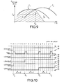
- the mode of use of the valves is determined, from the operation of the engine, using a diagram as shown in FIG. 9 which is a diagram on which the torque (ordinates) and the speed (abscissas) of this engine are represented according to the number of active valves per cylinder.
- FIG. 9 is a diagram on which the torque (ordinates) and the speed (abscissas) of this engine are represented according to the number of active valves per cylinder.
- two curves C 1 and C 2 have been obtained so as to delimit the operating zones (torque, speed) accessible to this engine according to a single intake valve (curve C 1 ) or two intake (curve C 2 ) are activated per cylinder.
- the use a single intake valve allows to obtain at low speed higher torque than using two valves intake. Conversely, at high speed, the use of two intake valves helps deliver higher torque.
- zones Z 1 or Z 2 are represented in FIG. 9 by zones Z 1 or Z 2 such that, when the engine operates at a required torque C and at a given speed R H , the mode corresponding to the zone where the coordinate point H is located. (C H , R H ) is preferred.
- FIG. 10 Such an operation is shown in Figure 10 where the operating modes "instructions" are represented ordered corresponding to a 90 mode with two valves or 92 with a single intake valve.
- the lifting mode operated for these valves is selected according to the parameters of engine operation, valve opening taking place according to a ballistic lifting mode, or according to a lifting mode classic.
- the opening and closing times of the valves are determined and controlled, while following a ballistic mode, the instant of closure of a valve is not controlled but determined by the time it takes for it to go from one closed position to open position then, without stopping, return in the closed position.
- the classic mode uses a valve open signal and valve close signal while that ballistic mode only uses an opening signal.
- FIG 11 is shown the lifting mode used for active valves depending on conditions (engine speed, torque). It appears that the ballistic lifting mode is particularly favorable when the engine speed is low, for example when the engine runs at idle.
- a new time delay will be taken account before the first application of the triggered mode.
- the torque setpoint is oscillating it is preferable apply a time delay to prevent immediate passage from classic to ballistic mode, that is to say that the couple setpoint must have a value below a threshold hysterisis for a period at least equal to the time delay to switch from classic survey mode to survey mode ballistic. So whenever the torque becomes lower at a hysterisis value the timer is started.
- the change of lifting mode depends on a range of stability such as the threshold (curve 120c) for triggering the conventional lifting mode is distinct from the threshold (curve 120b) of ballistic lift.
Landscapes
- Engineering & Computer Science (AREA)
- Mechanical Engineering (AREA)
- General Engineering & Computer Science (AREA)
- Chemical & Material Sciences (AREA)
- Combustion & Propulsion (AREA)
- Output Control And Ontrol Of Special Type Engine (AREA)
- Valve Device For Special Equipments (AREA)
Applications Claiming Priority (2)
| Application Number | Priority Date | Filing Date | Title |
|---|---|---|---|
| FR0209549A FR2842865B1 (fr) | 2002-07-26 | 2002-07-26 | Moteur a combustion interne muni d'un processeur et de cylindres dont chacun comporte au moins deux soupapes d'admision a commande electromecanique |
| FR0209549 | 2002-07-26 |
Publications (2)
| Publication Number | Publication Date |
|---|---|
| EP1408202A2 true EP1408202A2 (de) | 2004-04-14 |
| EP1408202A3 EP1408202A3 (de) | 2005-12-07 |
Family
ID=30011536
Family Applications (1)
| Application Number | Title | Priority Date | Filing Date |
|---|---|---|---|
| EP03300071A Withdrawn EP1408202A3 (de) | 2002-07-26 | 2003-07-21 | Brennkraftmaschine versehen mit einem Prozessor und Zylindern, wovon jeder minimal zwei elektromagnetische Einlassventile enthält |
Country Status (2)
| Country | Link |
|---|---|
| EP (1) | EP1408202A3 (de) |
| FR (1) | FR2842865B1 (de) |
Cited By (2)
| Publication number | Priority date | Publication date | Assignee | Title |
|---|---|---|---|---|
| WO2012085448A1 (fr) * | 2010-12-22 | 2012-06-28 | Valeo Systemes De Controle Moteur | Dispositif de commande d'un moteur thermique |
| CN107489538A (zh) * | 2016-06-09 | 2017-12-19 | 福特环球技术公司 | 用于包括停用发动机汽缸的发动机的活动汽缸配置 |
Family Cites Families (5)
| Publication number | Priority date | Publication date | Assignee | Title |
|---|---|---|---|---|
| US5190013A (en) * | 1992-01-10 | 1993-03-02 | Siemens Automotive L.P. | Engine intake valve selective deactivation system and method |
| GB9222353D0 (en) * | 1992-10-23 | 1992-12-09 | Ricardo Consulting Eng | Spark ignited internal combustion engines |
| US5327856A (en) * | 1992-12-22 | 1994-07-12 | General Motors Corporation | Method and apparatus for electrically driving engine valves |
| WO1999047800A1 (en) * | 1998-03-19 | 1999-09-23 | Hitachi, Ltd. | Internal combustion engine, control apparatus for an internal combustion engine, and its control method |
| KR100404773B1 (ko) * | 2000-03-21 | 2003-11-07 | 도요다 지도샤 가부시끼가이샤 | 전자구동밸브를 가지는 내연기관 |
-
2002
- 2002-07-26 FR FR0209549A patent/FR2842865B1/fr not_active Expired - Fee Related
-
2003
- 2003-07-21 EP EP03300071A patent/EP1408202A3/de not_active Withdrawn
Non-Patent Citations (1)
| Title |
|---|
| None |
Cited By (3)
| Publication number | Priority date | Publication date | Assignee | Title |
|---|---|---|---|---|
| WO2012085448A1 (fr) * | 2010-12-22 | 2012-06-28 | Valeo Systemes De Controle Moteur | Dispositif de commande d'un moteur thermique |
| FR2969706A1 (fr) * | 2010-12-22 | 2012-06-29 | Valeo Sys Controle Moteur Sas | Dispositif de commande d`un moteur thermique. |
| CN107489538A (zh) * | 2016-06-09 | 2017-12-19 | 福特环球技术公司 | 用于包括停用发动机汽缸的发动机的活动汽缸配置 |
Also Published As
| Publication number | Publication date |
|---|---|
| FR2842865A1 (fr) | 2004-01-30 |
| EP1408202A3 (de) | 2005-12-07 |
| FR2842865B1 (fr) | 2005-11-11 |
Similar Documents
| Publication | Publication Date | Title |
|---|---|---|
| FR2849675A1 (fr) | Moteur a combustion interne et procede de commande du calage des soupapes | |
| FR2520443A1 (fr) | Regulateur du ralenti d'un moteur a deplacement variable | |
| FR2797304A1 (fr) | Procede de commande d'un moteur a combustion en vue de faciliter le demarrage du moteur apres un arret | |
| FR2851613A1 (fr) | Dispositif de commande de la quantite d'admission dans un moteur a combustion interne | |
| WO2005113966A1 (fr) | Procede de commande de fonctionnement d'un groupe de cylindres d'un moteur a combustion interne | |
| EP0727010B1 (de) | Verfahren und vorrichtung zur steuerung des hubes eines ventils einer brennkraftmaschine | |
| EP1408202A2 (de) | Brennkraftmaschine versehen mit einem Prozessor und Zylindern, wovon jeder minimal zwei elektromagnetische Einlassventile enthält | |
| EP1384862B1 (de) | Verfahren und Vorrichtung zur Regelung einer Brennkraftmaschine | |
| EP1384863B1 (de) | Brennkraftmaschine mit einem Prozessor und elektromagnetischen Ventilaktuatoren | |
| EP1384861B1 (de) | Brennkraftmaschine mit Prozessor und Elektromechanische Antriebe zur Ventilsteuerung | |
| EP0027949A1 (de) | Variable Ventilsteuerung für Brennkraftmaschinen mit Hubventilen und Nockenwelle | |
| WO2016156699A1 (fr) | Procede de demarrage automatique d'un moteur a combustion interne a allumage commande | |
| EP3308005A1 (de) | Verfahren zum erhalten einer luftdrehmomentreserve für einen verbrennungsmotor | |
| EP1209341B1 (de) | Verfahren zur Steuerung eines Verbrennungsmotors zur Optimierung des Starts | |
| FR2965303A1 (fr) | Procede d'arret d'un moteur diesel ayant aux moins deux cylindres | |
| FR2671377A1 (fr) | Dispositif de commande de soupape a fonction de mise a l'arret pour moteur a combustion interne. | |
| FR2796421A1 (fr) | Procede de commande d'un moteur a combustion en vue de compenser la defaillance d'une soupape | |
| FR3051226B1 (fr) | Procede de pilotage d’au moins un dephaseur d’un moteur thermique de vehicule automobile lors d’une phase d’arret | |
| EP1163437B1 (de) | Methode für das regeln der leerlaufdrehzahl einer verbrennungsmaschine mit ventilen ohne nockenwellen | |
| FR2795133A1 (fr) | Procede de commande d'un moteur a combustion en vue de l'obtention d'un effet de frein moteur | |
| FR2939476A1 (fr) | Procede pour controler le fonctionnement d'un moteur a combustion interne avec desactivation d'au moins un cylindre | |
| FR2979123A1 (fr) | Moteur ameliore a combustion externe pour un vehicule automobile | |
| FR2900199A1 (fr) | Procede de creation d'un couple negatif par un moteur a combustion interne et de reglage de la valeur dudit couple | |
| EP1519012A2 (de) | Ventilsteuerungseinrichtung in einem Brennkraftmaschine, und Brennkraftmaschine mit derselben | |
| JPH05280317A (ja) | 内燃機関の可変動弁機構 |
Legal Events
| Date | Code | Title | Description |
|---|---|---|---|
| PUAI | Public reference made under article 153(3) epc to a published international application that has entered the european phase |
Free format text: ORIGINAL CODE: 0009012 |
|
| AK | Designated contracting states |
Kind code of ref document: A2 Designated state(s): AT BE BG CH CY CZ DE DK EE ES FI FR GB GR HU IE IT LI LU MC NL PT RO SE SI SK TR |
|
| AX | Request for extension of the european patent |
Extension state: AL LT LV MK |
|
| PUAL | Search report despatched |
Free format text: ORIGINAL CODE: 0009013 |
|
| AK | Designated contracting states |
Kind code of ref document: A3 Designated state(s): AT BE BG CH CY CZ DE DK EE ES FI FR GB GR HU IE IT LI LU MC NL PT RO SE SI SK TR |
|
| AX | Request for extension of the european patent |
Extension state: AL LT LV MK |
|
| 17P | Request for examination filed |
Effective date: 20060120 |
|
| AKX | Designation fees paid |
Designated state(s): AT BE BG CH CY CZ DE DK EE ES FI FR GB GR HU IE IT LI LU MC NL PT RO SE SI SK TR |
|
| 17Q | First examination report despatched |
Effective date: 20100203 |
|
| RAP1 | Party data changed (applicant data changed or rights of an application transferred) |
Owner name: PSA AUTOMOBILES SA |
|
| STAA | Information on the status of an ep patent application or granted ep patent |
Free format text: STATUS: EXAMINATION IS IN PROGRESS |
|
| GRAP | Despatch of communication of intention to grant a patent |
Free format text: ORIGINAL CODE: EPIDOSNIGR1 |
|
| STAA | Information on the status of an ep patent application or granted ep patent |
Free format text: STATUS: GRANT OF PATENT IS INTENDED |
|
| INTG | Intention to grant announced |
Effective date: 20181221 |
|
| RIC1 | Information provided on ipc code assigned before grant |
Ipc: F01L 9/04 20060101AFI20040226BHEP |
|
| STAA | Information on the status of an ep patent application or granted ep patent |
Free format text: STATUS: THE APPLICATION IS DEEMED TO BE WITHDRAWN |
|
| 18D | Application deemed to be withdrawn |
Effective date: 20190501 |