EP1408253A2 - Magnetorheologischer Kolben mit Kern - Google Patents
Magnetorheologischer Kolben mit Kern Download PDFInfo
- Publication number
- EP1408253A2 EP1408253A2 EP03077907A EP03077907A EP1408253A2 EP 1408253 A2 EP1408253 A2 EP 1408253A2 EP 03077907 A EP03077907 A EP 03077907A EP 03077907 A EP03077907 A EP 03077907A EP 1408253 A2 EP1408253 A2 EP 1408253A2
- Authority
- EP
- European Patent Office
- Prior art keywords
- core
- coil
- piston
- magnetorheological
- piece
- Prior art date
- Legal status (The legal status is an assumption and is not a legal conclusion. Google has not performed a legal analysis and makes no representation as to the accuracy of the status listed.)
- Granted
Links
Images
Classifications
-
- F—MECHANICAL ENGINEERING; LIGHTING; HEATING; WEAPONS; BLASTING
- F16—ENGINEERING ELEMENTS AND UNITS; GENERAL MEASURES FOR PRODUCING AND MAINTAINING EFFECTIVE FUNCTIONING OF MACHINES OR INSTALLATIONS; THERMAL INSULATION IN GENERAL
- F16F—SPRINGS; SHOCK-ABSORBERS; MEANS FOR DAMPING VIBRATION
- F16F9/00—Springs, vibration-dampers, shock-absorbers, or similarly-constructed movement-dampers using a fluid or the equivalent as damping medium
- F16F9/32—Details
- F16F9/3207—Constructional features
- F16F9/3214—Constructional features of pistons
-
- F—MECHANICAL ENGINEERING; LIGHTING; HEATING; WEAPONS; BLASTING
- F16—ENGINEERING ELEMENTS AND UNITS; GENERAL MEASURES FOR PRODUCING AND MAINTAINING EFFECTIVE FUNCTIONING OF MACHINES OR INSTALLATIONS; THERMAL INSULATION IN GENERAL
- F16F—SPRINGS; SHOCK-ABSORBERS; MEANS FOR DAMPING VIBRATION
- F16F9/00—Springs, vibration-dampers, shock-absorbers, or similarly-constructed movement-dampers using a fluid or the equivalent as damping medium
- F16F9/32—Details
- F16F9/53—Means for adjusting damping characteristics by varying fluid viscosity, e.g. electromagnetically
- F16F9/535—Magnetorheological [MR] fluid dampers
Definitions
- the present invention relates generally to piston dampers, and more particularly to a magnetorheological (MR) piston.
- MR magnetorheological
- Conventional piston dampers include MR dampers having a cylinder containing an MR fluid and having an MR piston which slideably engages the cylinder.
- the MR fluid passes through an orifice of the MR piston.
- Exposing the MR fluid in the orifice to a varying magnetic field, generated by providing a varying electric current to an electric coil of the MR piston varies the damping effect of the MR fluid in the orifice providing variably-controlled damping of relative motion between the MR piston and the cylinder.
- the electric current is varied to accommodate varying operating conditions, as is known to those skilled in the art.
- a rod has a first end attached to the upper end of the MR piston and a second end extending outside the cylinder. The cylinder and the rod are attached to separate structures to dampen relative motion of the two structures along the direction of piston travel.
- a known design includes an MR piston having a substantially annular, magnetically energizable passageway (the above-described orifice) and a magnetically non-energizable passageway (also called a bypass) positioned radially inward from the magnetically energizable passageway.
- the MR piston includes a one-piece piston core machined from a steel bar, an electric coil (also called an MR piston coil) disposed in a circumferential recess of the piston core, upper and lower piston plates longitudinally bounding the MR piston core, and a piston ring circumferentially surrounding the piston core and the coil.
- the coil is a wound length of electrically-insulated wire having one end electrically attached to an electrically-insulated electrode which passes through the piston core and having the other end grounded to the piston core.
- a plastic lining is molded over the piston core and to the wall of the electrode/coil wire passageway of the piston core to further insulate the piston core from the coil and to locate the electrode through the center of the passageway of the piston core.
- Another layer of plastic is molded over the coil to protect the wire from damage from the velocity of the MR fluid flow in the magnetically energizable passageway formed from a longitudinal space between the piston ring and the piston core/coil assembly.
- a magnetorheological piston in a first expression of an embodiment of the invention, includes a magnetorheological-piston coil and a magnetorheological-piston core.
- the magnetorheological-piston coil has a longitudinal axis and has an inner-diameter portion and an outer-diameter portion.
- the magnetorheological-piston core includes separate upper core, center core, and lower core pieces.
- the center core piece is located longitudinally between the upper core and lower core pieces and has a circumferential surface positioned radially inward from the inner-diameter portion of the coil.
- the coil is longitudinally positioned between the upper core and lower core pieces.
- a magnetorheological piston in a second expression of an embodiment of the invention, includes a magnetorheological-piston coil and a magnetorheological-piston core.
- the magnetorheological-piston coil has a longitudinal axis and has an inner-diameter portion and an outer-diameter portion.
- the magnetorheological-piston core includes separate upper core, center core, and lower core pieces.
- the center core piece is located longitudinally between the upper core and lower core pieces and has a circumferential surface positioned radially inward from the inner-diameter portion of the coil.
- the coil is longitudinally positioned between the upper core and lower core pieces.
- Each of the upper core, center core, and lower core pieces is a powder-metal core piece.
- a magnetorheological piston in a third expression of an embodiment of the invention, includes a magnetorheological-piston coil, a magnetorheological-piston core, a nonmagnetic sleeve, and an electrically-insulating coil end piece.
- the magnetorheological-piston coil has a longitudinal axis and has an inner-diameter portion and an outer-diameter portion.
- the magnetorheological-piston core includes separate upper core, center core, and lower core pieces.
- the center core piece is located longitudinally between the upper core and lower core pieces and has a circumferential surface positioned radially inward from the inner-diameter portion of the coil.
- the coil is longitudinally positioned between the upper core and lower core pieces.
- Each of the upper core, center core, and lower core pieces is a powder-metal core piece.
- the sleeve is longitudinally bounded by the upper core and lower core pieces and circumferentially surrounds the coil.
- the sleeve has an inner surface facing the coil and has an outer surface which defines an inner wall portion of a magnetically energizable passageway.
- the electrically-insulating coil end piece is longitudinally disposed between and in contact with the lower core piece and the coil and is longitudinally disposed between and in contact with the lower core and center core pieces.
- a magnetorheological piston in a fourth expression of an embodiment of the invention, includes a magnetorheological-piston coil and a magnetorheological-piston core.
- the magnetorheological-piston coil has a longitudinal axis.
- the magnetorheological-piston core includes at least two separate core pieces, wherein each of the core pieces is a powder-metal core piece, and wherein the coil is positioned to circumferentially surround at least a portion of at least one of the core pieces.
- Having a nonmagnetic sleeve provide protection for the coil wire from the velocity of the MR fluid eliminates the prior art step of over-molding the coil.
- Having the electrically-insulating coil end piece and an electrically-insulating coating on those portions of the upper core and center core pieces eliminates the plastic lining of the prior art.
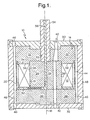
- Figure 1 is a cross-sectional view of an embodiment of the magnetorheological piston of the invention.
- FIG. 1 shows an embodiment of a magnetorheological piston 10 of the present invention.
- a magnetorheological piston is also known as a magnetorheological damper piston.
- a magnetorheological piston is a component of a magnetorheological damper (not shown), and in one application a magnetorheological damper is used as a shock absorber for an automobile, an airplane, or other type of vehicle.
- Another application of a magnetorheological damper is to provide motion resistance on exercise equipment such as stair climbers and rowing machines.
- a further application of a magnetorheological damper is to provide motion isolation for a building, bridge, or other structure subject to earthquakes.
- An additional application of a magnetorheological damper is to dampen vibrations encountered by vehicles and structures in outer space. Other applications are left to the artisan.
- the magnetorheological piston 10 includes a magnetorheological-piston coil 12 and a magnetorheological-piston core 14.
- the magnetorheological-piston coil 12 has a longitudinal axis 16 and has an inner-diameter portion 18 and an outer-diameter portion 20.
- the magnetorheological-piston core 14 includes separate upper core, center core, and lower core pieces 22, 24, and 26.
- the center core piece 24 is disposed longitudinally between the upper core and lower core pieces 22 and 26 and has a circumferential surface 28 disposed radially inward from the inner-diameter portion 18 of the coil 12.
- the coil 12 is longitudinally disposed between the upper core and lower core pieces 22 and 26.
- the center core piece 24 is in contact with the upper core and lower core pieces 22 and 26.
- the magnetorheological piston 10 also includes an upper piston plate 30 disposed longitudinally above and in contact with the upper core piece 22 and includes a lower piston plate 32 disposed longitudinally below and in contact with the lower core piece 26.
- the core pieces 22, 24, and 26 are pressed together between the piston plates 30 and 32.
- the upper core, center core, and lower core pieces 22, 24, and 26 are non-machined core pieces.
- the upper core piece 22 is a monolithic upper core piece
- the center core piece 24 is a monolithic center core piece
- the lower core piece 26 is a monolithic lower core piece.
- the coil 12 has an upper end portion 34, and the upper core piece 22 has a lower surface portion 36 which has an electrically-insulating coating 38 and which is in contact with the entire upper end portion 34 of the coil 12.
- the circumferential surface 28 of the center core piece 24 has an electrically-insulating coating 39 and is in contact with the entire inner-diameter portion 18 of the coil 12.
- Use of a thin insulation coating eliminates use of the plastic lining of the prior art and provides more room for the coil or reduces dead length.
- the coil 12 is wound to a bobbin (not shown) which supports the electrode, wherein the bobbin is assembled to the rest of the core components in the build up of the core thus eliminating handling of the core pieces in the winder (not shown).
- each of the upper core, center core, and lower core pieces 22, 24, and 26 is a powder-metal core piece.
- the powder metal consists essentially of steel powder-metal.
- each of the upper core, center core, and lower core pieces 22, 24, and 26 is a surface-ground powder-metal core piece. It is noted using powder-metal for the upper core, center core, and lower core pieces 22, 24, and 26 creates a magnetorheological-piston core 14 without expensive machining of a steel bar as is done in the prior art. It is also noted that using surface ground core pieces controls stack-up of the assembly.
- the upper core, center core, and lower core pieces 22, 24, and 26 include aligned and longitudinally extending portions of a magnetically non-energizable passageway (also called a bypass) 40.
- a magnetically non-energizable passageway also called a bypass 40. It is pointed out that it is difficult to create a single-piece magnetorheological-piston core from powder-metal which includes a longitudinally-through passageway of dimensions to function as a bypass in a vehicle damper. It is also pointed out that, in one vehicle-damper arrangement, the portion of the magnetically non-energizable passageway 40 in the upper core piece 22 is tapered, as shown in Figure 1, to meet a required powder-metal passageway wall thickness.
- a restriction plate 42 is disposed between the lower core piece 26 and the lower piston plate 32 to limit the flow of magnetorheological fluid (not shown) in the magnetically non-energizable passageway 40.
- each of the core pieces 22, 24, and 26 is an impact-extruded core piece or a forged core piece. Other constructions are left to the artisan.
- the magnetorheological piston 10 also includes a nonmagnetic sleeve 44 longitudinally bounded by the upper core and lower core pieces 22 and 26 and circumferentially surrounding the coil 12.
- the sleeve 44 consists essentially of nonmagnetic stainless steel.
- the sleeve 44 has an inner surface facing the coil 12 and has an outer surface which defines an inner wall portion of a magnetically energizable passageway 46 whose outer wall portion is defined by the inner surface of a piston ring 48 which is attached to the upper and lower piston plates 30 and 32.
- the magnetorheological piston 10 additionally includes an electrically-insulating coil end piece 50 which is longitudinally disposed between and in contact with the lower core piece 26 and the coil 12 and which is longitudinally disposed between and in contact with the lower core and center core pieces 26 and 24.
- the upper core piece 22 has a longitudinally extending through hole 52 coaxially aligned with the longitudinal axis 16 of the coil 12 for receiving a rod 54 containing at least a portion of an electrode 56.
- the coil 12 has a first end in electrical contact with the electrode 56 of the received rod 54 through a passageway extending radially in the coil end piece 50 and extending longitudinally in the center core piece 24.
- the coil 12 has a second end in electrical-grounding contact with one of the upper core, center core, and lower core pieces 22, 24, and 26.
- the magnetorheological piston 10 includes a magnetorheological-piston coil 12 and a magnetorheological-piston core 14.
- the magnetorheological-piston coil 12 has a longitudinal axis 16 and has an inner-diameter portion 18 and an outer-diameter portion 20.
- the magnetorheological-piston core 14 includes separate upper core, center core, and lower core pieces 22, 24, and 26.
- the center core piece 24 is disposed longitudinally between the upper core and lower core pieces 22 and 26 and has a circumferential surface 28 disposed radially inward from the inner-diameter portion 18 of the coil 12.
- the coil 12 is longitudinally disposed between the upper core and lower core pieces 22 and 26.
- Each of the upper core, center core, and lower core pieces 22, 24, and 26 is a powder-metal core piece. Examples, etc. of the first expression are equally applicable to the second expression of the embodiment of Figure 1.
- the magnetorheological piston 10 includes a magnetorheological-piston coil 12, a magnetorheological-piston core 14, a nonmagnetic sleeve 44, and an electrically-insulating coil end piece 50.
- the magnetorheological-piston coil 12 has a longitudinal axis 16 and has an inner-diameter portion 18 and an outer-diameter portion 20.
- the magnetorheological-piston core 14 includes separate upper core, center core, and lower core pieces 22, 24, and 26.
- the center core piece 24 is disposed longitudinally between the upper core and lower core pieces 22 and 26 and has a circumferential surface 28 disposed radially inward from the inner-diameter portion 18 of the coil 12.
- the coil 12 is longitudinally disposed between the upper core and lower core pieces 22 and 26.
- Each of the upper core, center core, and lower core pieces 22, 24, and 26 is a powder-metal core piece.
- the sleeve 44 is longitudinally bounded by the upper core and lower core pieces 22 and 26 and circumferentially surrounds the coil 12.
- the sleeve 44 has an inner surface facing the coil 12 and has an outer surface which defines an inner wall portion of a magnetically energizable passageway 46.
- the electrically-insulating coil end piece 50 is longitudinally disposed between and in contact with the lower core piece 26 and the coil 12 and is longitudinally disposed between and in contact with the lower core and center core pieces 26 and 24. Examples, etc. of the first expression are equally applicable to the third expression of the embodiment of Figure 1.
- a magnetorheological piston in a fourth expression of an embodiment of the invention, includes a magnetorheological-piston coil and a magnetorheological-piston core.
- the magnetorheological-piston coil has a longitudinal axis.
- the magnetorheological-piston core includes at least two separate core pieces, wherein each of the core pieces is a powder-metal core piece, and wherein the coil is positioned to circumferentially surround at least a portion of at least one of the core pieces.
- each core piece is a monolithic core piece.
- the first core piece has the combined shape of the upper and center core pieces 22 and 24, and the second core piece has the shape of the lower core piece 26.
- the first core piece has the shape of the upper core piece 22, and the second core piece has the combined shape of the center and lower core pieces 24 and 26.
- Other examples having two or more core pieces are left to the artisan.
- Having a nonmagnetic sleeve provide protection for the coil wire from the velocity of the MR fluid eliminates the prior art step of over-molding the coil.
- Having the electrically-insulating coil end piece and an electrically-insulating coating on those portions of the upper core and center core pieces eliminates the plastic lining of the prior art.
Landscapes
- Engineering & Computer Science (AREA)
- General Engineering & Computer Science (AREA)
- Mechanical Engineering (AREA)
- Physics & Mathematics (AREA)
- Electromagnetism (AREA)
- Fluid-Damping Devices (AREA)
- Soft Magnetic Materials (AREA)
Applications Claiming Priority (2)
| Application Number | Priority Date | Filing Date | Title |
|---|---|---|---|
| US10/266,367 US6655511B1 (en) | 2002-10-08 | 2002-10-08 | Magnetorheological piston having a core |
| US266367 | 2002-10-08 |
Publications (3)
| Publication Number | Publication Date |
|---|---|
| EP1408253A2 true EP1408253A2 (de) | 2004-04-14 |
| EP1408253A3 EP1408253A3 (de) | 2004-06-16 |
| EP1408253B1 EP1408253B1 (de) | 2006-10-25 |
Family
ID=29549734
Family Applications (1)
| Application Number | Title | Priority Date | Filing Date |
|---|---|---|---|
| EP03077907A Expired - Lifetime EP1408253B1 (de) | 2002-10-08 | 2003-09-15 | Magnetorheologischer Kolben mit Kern |
Country Status (3)
| Country | Link |
|---|---|
| US (1) | US6655511B1 (de) |
| EP (1) | EP1408253B1 (de) |
| DE (1) | DE60309265T2 (de) |
Cited By (3)
| Publication number | Priority date | Publication date | Assignee | Title |
|---|---|---|---|---|
| CN103290943A (zh) * | 2013-05-30 | 2013-09-11 | 河海大学 | 多用途主动可控的大出力隔震减振装置 |
| CN103470674A (zh) * | 2013-09-30 | 2013-12-25 | 湘潭大学 | 一种内通道式汽车悬架系统磁流变减振器 |
| CN112105836A (zh) * | 2018-07-03 | 2020-12-18 | 纽摩泰科有限公司 | 磁流变阻尼器活塞 |
Families Citing this family (17)
| Publication number | Priority date | Publication date | Assignee | Title |
|---|---|---|---|---|
| US6981577B2 (en) * | 2003-03-31 | 2006-01-03 | Kabushiki Kaisha Hitachi Seisakusho | Controlling damping force shock absorber |
| US6948312B1 (en) * | 2004-03-29 | 2005-09-27 | Delphi Technologies, Inc. | High-performance piston core for a magnetorheological damper |
| US7878312B2 (en) * | 2006-05-31 | 2011-02-01 | University Of Maryland | Adaptive energy absorption system for a vehicle seat |
| US7822522B2 (en) * | 2006-05-31 | 2010-10-26 | Techno-Sciences, Inc. (corporation) | Adaptive energy absorption system for a vehicle seat |
| US7921973B2 (en) * | 2006-05-31 | 2011-04-12 | Techno-Sciences, Inc. | Adaptive energy absorption system for a vehicle seat |
| US7958979B2 (en) * | 2007-01-05 | 2011-06-14 | Honda Motor Co., Ltd. | Variable damper |
| KR100892999B1 (ko) * | 2007-09-17 | 2009-04-10 | 에스앤티대우(주) | 연속 감쇠력 가변형 댐퍼의 피스톤밸브 어셈블리 |
| US8286763B2 (en) * | 2008-01-29 | 2012-10-16 | Bwi Company Limited S.A. | Magnetorheological fluid-based device having a magnetorheological piston assembly |
| JP4996558B2 (ja) * | 2008-03-12 | 2012-08-08 | 本田技研工業株式会社 | 可変減衰力ダンパ |
| US9328791B2 (en) * | 2011-08-29 | 2016-05-03 | Honda Motor Co., Ltd. | Variable damping force damper |
| JP5619796B2 (ja) * | 2012-02-15 | 2014-11-05 | 本田技研工業株式会社 | 減衰力可変ダンパ |
| JP5986757B2 (ja) * | 2012-03-01 | 2016-09-06 | Kyb株式会社 | 磁気粘性流体緩衝器 |
| JP5828558B2 (ja) * | 2012-03-01 | 2015-12-09 | Kyb株式会社 | 磁気粘性流体緩衝器 |
| JP5865801B2 (ja) * | 2012-08-06 | 2016-02-17 | Kyb株式会社 | 磁気粘性流体緩衝器 |
| JP2015175515A (ja) * | 2014-03-18 | 2015-10-05 | カヤバ工業株式会社 | 磁気粘性流体緩衝器 |
| JP6093837B1 (ja) * | 2015-11-19 | 2017-03-08 | Kyb株式会社 | 磁気粘性流体緩衝器 |
| JP7737864B2 (ja) * | 2021-10-19 | 2025-09-11 | 株式会社栗本鐵工所 | 磁気粘性流体装置の製造方法 |
Family Cites Families (38)
| Publication number | Priority date | Publication date | Assignee | Title |
|---|---|---|---|---|
| JPS58221034A (ja) | 1982-06-16 | 1983-12-22 | Showa Mfg Co Ltd | 油圧緩衝器における減衰力調整装置 |
| JPS63180742A (ja) | 1987-01-19 | 1988-07-25 | Atsugi Motor Parts Co Ltd | 減衰力可変シヨツクアブソ−バ装置 |
| DE3712349C2 (de) | 1987-04-11 | 1994-07-07 | Bosch Gmbh Robert | Vorrichtung zur Dämpfung von Bewegungsabläufen |
| JPH04266636A (ja) | 1991-02-19 | 1992-09-22 | Kayaba Ind Co Ltd | 電気粘性流体利用の緩衝器 |
| JPH04321829A (ja) | 1991-04-20 | 1992-11-11 | Bridgestone Corp | 減衰装置用絞り通路 |
| US5277281A (en) * | 1992-06-18 | 1994-01-11 | Lord Corporation | Magnetorheological fluid dampers |
| US5284330A (en) | 1992-06-18 | 1994-02-08 | Lord Corporation | Magnetorheological fluid devices |
| US5259487A (en) | 1992-07-14 | 1993-11-09 | The Lubrizol Corporation | Adjustable dampers using electrorheological fluids |
| JP3151753B2 (ja) | 1992-07-20 | 2001-04-03 | カヤバ工業株式会社 | 油圧緩衝器 |
| JPH0650375A (ja) | 1992-07-31 | 1994-02-22 | Kayaba Ind Co Ltd | 緩衝器 |
| JPH0666342A (ja) | 1992-08-21 | 1994-03-08 | Kayaba Ind Co Ltd | 緩衝器 |
| US5333708A (en) | 1993-01-11 | 1994-08-02 | General Motors Corporation | Compression cut-off valve for a hydraulic damper |
| ES2106667B1 (es) | 1994-01-15 | 1998-05-16 | Fichtel & Sachs Ag | Instalacion de accionamiento de valvula, en particular para un amortiguador de vibraciones. |
| DE4433056C2 (de) | 1994-09-16 | 1998-01-29 | Mannesmann Sachs Ag | Schwingungsdämpfer für Kraftfahrzeuge |
| US5522481A (en) | 1994-12-09 | 1996-06-04 | Bridgestone/Firestone, Inc. | Vibration damping device using ER fluids |
| US5510988A (en) | 1994-12-19 | 1996-04-23 | General Motors Corporation | Vehicle chassis control system |
| US5598908A (en) * | 1995-06-05 | 1997-02-04 | Gse, Inc. | Magnetorheological fluid coupling device and torque load simulator system |
| US5590745A (en) | 1995-06-19 | 1997-01-07 | Bridgestone/Firestone, Inc. | Vibration damping device using ER fluids having multiple electrodes |
| US5588509A (en) | 1995-10-17 | 1996-12-31 | Bridgestone/Firestone, Inc. | Splined vibration damping device using ER fluids |
| US6065572A (en) | 1995-11-13 | 2000-05-23 | The Lubrizol Corporation | Polymeric materials to self-regulate the level of polar activators in electrorheological fluids |
| JP3874377B2 (ja) | 1996-05-15 | 2007-01-31 | カヤバ工業株式会社 | 緩衝器 |
| US5878851A (en) * | 1996-07-02 | 1999-03-09 | Lord Corporation | Controllable vibration apparatus |
| US6095486A (en) | 1997-03-05 | 2000-08-01 | Lord Corporation | Two-way magnetorheological fluid valve assembly and devices utilizing same |
| US5947238A (en) | 1997-03-05 | 1999-09-07 | Lord Corporation | Passive magnetorheological fluid device with excursion dependent characteristic |
| US6394239B1 (en) | 1997-10-29 | 2002-05-28 | Lord Corporation | Controllable medium device and apparatus utilizing same |
| US6131709A (en) | 1997-11-25 | 2000-10-17 | Lord Corporation | Adjustable valve and vibration damper utilizing same |
| DE19820570A1 (de) | 1998-05-08 | 1999-11-11 | Schenck Ag Carl | Schwingungsdämpfer auf Basis elektrorheologischer und/oder magnetorheologischer Flüssigkeiten |
| US6161662A (en) | 1999-03-16 | 2000-12-19 | Delphi Technologies, Inc. | Suspension damper for motor vehicle |
| US6318521B1 (en) | 1999-06-16 | 2001-11-20 | Bridgestone/Firestone, Inc. | Externally guided ER damper |
| US6318520B1 (en) | 1999-09-13 | 2001-11-20 | Delphi Technologies, Inc. | Magnetorheological fluid damper tunable for smooth transitions |
| US6318519B1 (en) | 1999-09-13 | 2001-11-20 | Delphi Technologies, Inc. | Magnetorheological fluid damper tunable for smooth transitions |
| US6279701B1 (en) | 1999-09-13 | 2001-08-28 | Delphi Technologies, Inc. | Magnetorheological fluid damper with multiple annular flow gaps |
| US6311810B1 (en) | 1999-10-21 | 2001-11-06 | Delphi Technologies, Inc. | Magnetorheological fluid damper |
| US6260675B1 (en) | 2000-01-31 | 2001-07-17 | Delphi Technologies, Inc. | Magnetorheological fluid damper |
| DE60018956T2 (de) * | 2000-12-29 | 2006-03-23 | Mando Corp. | Zweirohr-Schwingungsdämpfer, gefüllt mit hydraulischer Flüssigkeit und magnetorheologischer Flüssigkeit |
| US6279702B1 (en) | 2001-01-05 | 2001-08-28 | Mando Corporation | Shock absorber using a hydraulic fluid and a magnetorheological fluid |
| US6419058B1 (en) * | 2001-03-30 | 2002-07-16 | Delphi Technologies, Inc. | Magnetorheological damper with piston bypass |
| US6612409B2 (en) * | 2001-12-27 | 2003-09-02 | Delphi Technologies, Inc. | Magneotorheological piston and damper |
-
2002
- 2002-10-08 US US10/266,367 patent/US6655511B1/en not_active Expired - Lifetime
-
2003
- 2003-09-15 EP EP03077907A patent/EP1408253B1/de not_active Expired - Lifetime
- 2003-09-15 DE DE60309265T patent/DE60309265T2/de not_active Expired - Lifetime
Cited By (5)
| Publication number | Priority date | Publication date | Assignee | Title |
|---|---|---|---|---|
| CN103290943A (zh) * | 2013-05-30 | 2013-09-11 | 河海大学 | 多用途主动可控的大出力隔震减振装置 |
| CN103290943B (zh) * | 2013-05-30 | 2015-06-17 | 河海大学 | 多用途主动可控的大出力隔震减振装置 |
| CN103470674A (zh) * | 2013-09-30 | 2013-12-25 | 湘潭大学 | 一种内通道式汽车悬架系统磁流变减振器 |
| CN103470674B (zh) * | 2013-09-30 | 2015-10-21 | 湘潭大学 | 一种内通道式汽车悬架系统磁流变减振器 |
| CN112105836A (zh) * | 2018-07-03 | 2020-12-18 | 纽摩泰科有限公司 | 磁流变阻尼器活塞 |
Also Published As
| Publication number | Publication date |
|---|---|
| US6655511B1 (en) | 2003-12-02 |
| DE60309265T2 (de) | 2007-09-06 |
| EP1408253A3 (de) | 2004-06-16 |
| DE60309265D1 (de) | 2006-12-07 |
| EP1408253B1 (de) | 2006-10-25 |
Similar Documents
| Publication | Publication Date | Title |
|---|---|---|
| US6655511B1 (en) | Magnetorheological piston having a core | |
| EP1323947B1 (de) | Magnetorheologische Kolben und Dämpfer | |
| JP5743785B2 (ja) | 電磁サスペンション | |
| US6336535B1 (en) | Magneto-rheological damper with dual flux ring spacer | |
| EP1255058B1 (de) | Temperaturkompensierender Flussring | |
| EP2037150B1 (de) | Magnetorheologischer Kolben, Anordnung eines magnetorheologischen Kolbens, magnetorheologisches Dämpfungssystem | |
| US6866127B2 (en) | Piston damper assembly, and dust tube subassembly, having a velocity sensor | |
| US6419058B1 (en) | Magnetorheological damper with piston bypass | |
| US6948312B1 (en) | High-performance piston core for a magnetorheological damper | |
| US20100089711A1 (en) | Magnetorheological devices with permanent magnet field bias | |
| US20150129378A1 (en) | Magnetorheological fluid damper | |
| JPH02296024A (ja) | ロータリショックアブソーバ | |
| CN104019180A (zh) | 电磁悬架装置 | |
| US20030029683A1 (en) | Magnetorheological strut piston with compression bypass | |
| US10711861B1 (en) | Controllable oleo-pneumatic damper using magnetorheological fluid | |
| US20060260891A1 (en) | Magnetorheological piston assembly and damper | |
| CA1138904A (en) | Vibration isolator | |
| JPH07208629A (ja) | 弁操作装置 | |
| US6422361B2 (en) | Damper, piston assembly and method for making | |
| US7753180B2 (en) | Magnetorheological piston having a bypass passageway | |
| US20080272871A1 (en) | Armature and solenoid assembly | |
| WO2003095861A1 (en) | Magnetically actuated motion control device | |
| EP1835200B1 (de) | Kolbendämpfungsanordnung und Staubrohrunteranordnung mit Geschwindigkeitssensor | |
| JPS6210514Y2 (de) | ||
| JP2000078828A (ja) | 電磁式リニアアクチュエータ |
Legal Events
| Date | Code | Title | Description |
|---|---|---|---|
| PUAI | Public reference made under article 153(3) epc to a published international application that has entered the european phase |
Free format text: ORIGINAL CODE: 0009012 |
|
| AK | Designated contracting states |
Kind code of ref document: A2 Designated state(s): AT BE BG CH CY CZ DE DK EE ES FI FR GB GR HU IE IT LI LU MC NL PT RO SE SI SK TR |
|
| AX | Request for extension of the european patent |
Extension state: AL LT LV MK |
|
| PUAL | Search report despatched |
Free format text: ORIGINAL CODE: 0009013 |
|
| AK | Designated contracting states |
Kind code of ref document: A3 Designated state(s): AT BE BG CH CY CZ DE DK EE ES FI FR GB GR HU IE IT LI LU MC NL PT RO SE SI SK TR |
|
| AX | Request for extension of the european patent |
Extension state: AL LT LV MK |
|
| 17P | Request for examination filed |
Effective date: 20041216 |
|
| AKX | Designation fees paid |
Designated state(s): DE FR GB |
|
| 17Q | First examination report despatched |
Effective date: 20050310 |
|
| GRAP | Despatch of communication of intention to grant a patent |
Free format text: ORIGINAL CODE: EPIDOSNIGR1 |
|
| GRAS | Grant fee paid |
Free format text: ORIGINAL CODE: EPIDOSNIGR3 |
|
| GRAA | (expected) grant |
Free format text: ORIGINAL CODE: 0009210 |
|
| AK | Designated contracting states |
Kind code of ref document: B1 Designated state(s): DE FR GB |
|
| REG | Reference to a national code |
Ref country code: GB Ref legal event code: FG4D |
|
| REF | Corresponds to: |
Ref document number: 60309265 Country of ref document: DE Date of ref document: 20061207 Kind code of ref document: P |
|
| ET | Fr: translation filed | ||
| PLBE | No opposition filed within time limit |
Free format text: ORIGINAL CODE: 0009261 |
|
| STAA | Information on the status of an ep patent application or granted ep patent |
Free format text: STATUS: NO OPPOSITION FILED WITHIN TIME LIMIT |
|
| 26N | No opposition filed |
Effective date: 20070726 |
|
| GBPC | Gb: european patent ceased through non-payment of renewal fee |
Effective date: 20070915 |
|
| PG25 | Lapsed in a contracting state [announced via postgrant information from national office to epo] |
Ref country code: GB Free format text: LAPSE BECAUSE OF NON-PAYMENT OF DUE FEES Effective date: 20070915 |
|
| REG | Reference to a national code |
Ref country code: FR Ref legal event code: PLFP Year of fee payment: 14 |
|
| REG | Reference to a national code |
Ref country code: FR Ref legal event code: PLFP Year of fee payment: 15 |
|
| REG | Reference to a national code |
Ref country code: FR Ref legal event code: CA Effective date: 20171124 Ref country code: FR Ref legal event code: TP Owner name: BWI COMPANY LIMITED S.A., LU Effective date: 20171124 |
|
| REG | Reference to a national code |
Ref country code: FR Ref legal event code: PLFP Year of fee payment: 16 |
|
| PGFP | Annual fee paid to national office [announced via postgrant information from national office to epo] |
Ref country code: DE Payment date: 20180904 Year of fee payment: 16 Ref country code: FR Payment date: 20180813 Year of fee payment: 16 |
|
| REG | Reference to a national code |
Ref country code: DE Ref legal event code: R081 Ref document number: 60309265 Country of ref document: DE Owner name: BWI COMPANY LIMITED S.A., LU Free format text: FORMER OWNER: DELPHI TECHNOLOGIES, INC., TROY, MICH., US Ref country code: DE Ref legal event code: R082 Ref document number: 60309265 Country of ref document: DE |
|
| REG | Reference to a national code |
Ref country code: DE Ref legal event code: R119 Ref document number: 60309265 Country of ref document: DE |
|
| PG25 | Lapsed in a contracting state [announced via postgrant information from national office to epo] |
Ref country code: DE Free format text: LAPSE BECAUSE OF NON-PAYMENT OF DUE FEES Effective date: 20200401 |
|
| PG25 | Lapsed in a contracting state [announced via postgrant information from national office to epo] |
Ref country code: FR Free format text: LAPSE BECAUSE OF NON-PAYMENT OF DUE FEES Effective date: 20190930 |