EP1408302A2 - Für Längsbeschleunigung abstimmbarer Mikrokreisel - Google Patents
Für Längsbeschleunigung abstimmbarer Mikrokreisel Download PDFInfo
- Publication number
- EP1408302A2 EP1408302A2 EP03256281A EP03256281A EP1408302A2 EP 1408302 A2 EP1408302 A2 EP 1408302A2 EP 03256281 A EP03256281 A EP 03256281A EP 03256281 A EP03256281 A EP 03256281A EP 1408302 A2 EP1408302 A2 EP 1408302A2
- Authority
- EP
- European Patent Office
- Prior art keywords
- sensing
- gimbals
- sensing electrode
- microgyroscope
- oscillating
- Prior art date
- Legal status (The legal status is an assumption and is not a legal conclusion. Google has not performed a legal analysis and makes no representation as to the accuracy of the status listed.)
- Granted
Links
Images







Classifications
-
- G—PHYSICS
- G01—MEASURING; TESTING
- G01C—MEASURING DISTANCES, LEVELS OR BEARINGS; SURVEYING; NAVIGATION; GYROSCOPIC INSTRUMENTS; PHOTOGRAMMETRY OR VIDEOGRAMMETRY
- G01C19/00—Gyroscopes; Turn-sensitive devices using vibrating masses; Turn-sensitive devices without moving masses; Measuring angular rate using gyroscopic effects
-
- G—PHYSICS
- G01—MEASURING; TESTING
- G01C—MEASURING DISTANCES, LEVELS OR BEARINGS; SURVEYING; NAVIGATION; GYROSCOPIC INSTRUMENTS; PHOTOGRAMMETRY OR VIDEOGRAMMETRY
- G01C19/00—Gyroscopes; Turn-sensitive devices using vibrating masses; Turn-sensitive devices without moving masses; Measuring angular rate using gyroscopic effects
- G01C19/56—Turn-sensitive devices using vibrating masses, e.g. vibratory angular rate sensors based on Coriolis forces
- G01C19/5719—Turn-sensitive devices using vibrating masses, e.g. vibratory angular rate sensors based on Coriolis forces using planar vibrating masses driven in a translation vibration along an axis
- G01C19/5733—Structural details or topology
- G01C19/5755—Structural details or topology the devices having a single sensing mass
- G01C19/5762—Structural details or topology the devices having a single sensing mass the sensing mass being connected to a driving mass, e.g. driving frames
Definitions
- the present invention relates to a microgyroscope for sensing an angular velocity. More particularly, the present invention relates to a microgyroscope not readily affected by external disturbances, which is capable of synchronizing a sensing electrode and corresponding sensing gimbals in a same direction and/or with a same resonant frequency in a sensing direction thereby eliminating unnecessary signal output made due to an external translational acceleration caused by disturbances, such as noise, shock, and the like.
- a gyroscope is a sensing device that detects rotational angular velocity, and is currently in use as a core part for precision navigation in ships and airplanes.
- MEMS micro-electromechanical system
- a gyroscope operates based on a Coriolis force, which acts on a mass in a third axis direction when the mass, which is oscillating or rotating in a first axis direction, is applied with a force rotating at a constant angular velocity from a second axis direction normal to the first axis direction.
- the angular velocity is detected by sensing a change in the displacement of the sensing gimbals and a capacitance change.
- a conventional microgyroscope 10 of MEMS technology is provided with oscillating gimbals 12 that define an oscillating mass M a moving at a resonant frequency f a by an oscillating direction elastic body 13 that has a predetermined damping force, or a damper 15 and oscillates in a horizontal direction, i.e., in an X-axis direction, a drive electrode 16 having drive combs 17 arranged between oscillating combs 14 of the oscillating gimbals 12 at predetermined intervals and secured on a wafer 11, sensing gimbals 18 that define a sensing mass M s oscillating together with the oscillating gimbals 12 by a sensing direction elastic body 19 that has a predetermined damping force, or a damper 23, and then with application of rotational force at a constant angular velocity, oscillating in a vertical direction, i.e., in a Y-axis direction at a reson
- the oscillating gimbals 12 and the sensing gimbals 18 oscillate in the X-axis direction by the oscillating and drive combs 14, 17 at the resonant frequency f a .
- the oscillating gimbals 12 and the sensing gimbals 18 are subject to the Coriolis force in the Y-axis direction.
- the sensing gimbals 18 are oscillated in the Y-axis direction by the sensing direction elastic body 19. If the sensing gimbals 18 are displaced in the Y-axis direction by even a minute distance, e.g., from several tens of nanometers to several nanometers, a capacitance between the sensing combs 20 of the sensing gimbals 18 and the electrode combs 21 of the sensing electrode 22 varies. Accordingly, the voltage change thereof is detected as an angular velocity.
- the microgyroscope 10 is equally exposed to external disturbances, such as noise or shock. If the microgyroscope is subject to such a disturbance, the sensing gimbals 18 are displaced due to a translational acceleration.
- the translational acceleration particularly in the Y-axis direction, causes the sensing gimbals 18 to displace, and a subsequent sensing of unnecessary signals.
- the properties of the signals appearing during the vibration of the sensing gimbals 18 by the disturbance in the absence of input angular velocity ⁇ is expressed by: A cos ⁇ a t ⁇ cos ⁇ s t where ⁇ a is a resonant frequency of oscillating gimbals 12, ⁇ s is a resonant frequency of sensing gimbals 18, and A is an amplitude.
- One of the two frequency components is removed as it is passed through a low pass filter of a signal sensing circuit.
- the other frequency component which is 1/2 A [cos( ⁇ a - ⁇ s ) t , however, is not removed and thus remains even after having passed through the low pass filter. This is because the resonant frequency ⁇ s of the sensing gimbals 18 is set higher than the resonant frequency ⁇ a of oscillating gimbals 12 during the designing process to maximize sensitivity, thereby rendering a relatively small difference between the frequencies ⁇ a - ⁇ s .
- a microgyroscope tunable against an external translational acceleration, comprising an oscillating mass floating over a wafer to oscillate in a first direction, a driving electrode for oscillating the oscillating mass, a sensing mass oscillating together with the oscillating mass and concurrently moving in a second direction, wherein the second direction is perpendicular to the first direction, a sensing electrode for sensing a motion of the sensing mass, and a sensing electrode supporting portion for movably securing the sensing electrode so that the sensing electrode can move in the second direction with the sensing mass.
- the invention thus provides a microgyroscope not easily affected by external disturbances, which is capable of synchronizing a sensing electrode and corresponding sensing gimbals in a same direction and/or with a same resonant frequency thereby eliminating unnecessary signal output made due to an external translational acceleration caused by disturbances, such as noise, shock, and the like.
- the sensing electrode supporting portion may be formed as a sensing electrode elastic body elastically disposed between the sensing electrode and the wafer for moving the sensing electrode in the second direction.
- a resonant frequency of the sensing electrode in the second direction may either be equal to or similar to a resonant frequency of the sensing mass in the sensing direction.
- a microgyroscope tunable against an external translational acceleration comprising outer gimbals floating over a wafer to oscillate in a first direction, a plurality of first comb units arranged on an external side of the outer gimbals, at least one driving electrode unit having a plurality of second comb units arranged between the first comb units at predetermined intervals to oscillate the outer gimbals, inner gimbals movably arranged in the outer gimbals to oscillate together with the outer gimbals, while concurrently moving in a second direction, wherein the second direction is perpendicular to the first direction, a plurality of third comb units arranged in the second direction in one or more divisions defined in the interior of the inner gimbals, at least one sensing electrode unit arranged in the divisions of the inner gimbals, and having a plurality of electrode comb units that are arranged between the third comb units of the division
- the sensing electrode supporting portion may be formed as a sensing electrode beam elastic body elastically disposed between the sensing electrode unit and the wafer for oscillating the sensing electrode unit in the second direction.
- the sensing electrode beam elastic body may include an anchor secured on the wafer and extending upwards, and an elastic horizontal beam elastically disposed to connect both sides of the anchor with the sensing electrode unit.
- a resonant frequency of the sensing electrode in the sensing direction may be either equal to or similar to a resonant frequency of the inner gimbals in the second direction.
- Each of the first, the second and the third comb units may include a plurality of combs.
- the interior of the inner gimbals may be defined as a single, or a plurality of divisions where a plurality of third comb units are respectively arranged in both sides thereof, and the sensing electrode unit may include one, or a plurality of sensing electrodes arranged respectively in the single or plurality of divisions of the interior of the inner gimbals, and has a plurality of electrode comb units arranged between the third comb units at predetermined intervals.
- FIG. 3 schematically shows a microgyroscope 100 according to an embodiment of the present invention.
- the microgyroscope 100 is provided with oscillating gimbals 112 defining an oscillating mass M a floating over a wafer 111 to oscillate at a resonant frequency f a in a horizontal direction, i.e., in the X-axis direction, a driving electrode 116 secured on the wafer 111 and having driving combs 117 arranged between oscillating combs 114 of the oscillating gimbals 112 at predetermined intervals, sensing gimbals 118 defining a sensing mass M s arranged to oscillate at a resonant frequency f s in a vertical direction, i.e., in the Y-axis direction, when applied with an angular velocity ⁇ during oscillation together with the oscillating gimbals 112, a sensing electrode 122 movably secured on the wafer 111 and having electrode combs 121 arranged between sensing combs 120 of the sensing
- the oscillating gimbals 112 are oscillated in the X-axis direction by an oscillating direction elastic body 113 elastically disposed between the oscillating gimbals 112 and the wafer 111.
- the elastic body 113 is provided with a predetermined damping force, or a damper 115.
- the sensing gimbals 118 are oscillated in the X-axis direction together with the oscillating gimbals 112, and oscillated in a sensing direction, i.e., in the Y-axis direction, with the application of rotational force rotating at a predetermined angular velocity ⁇ .
- FIG. 3 shows the oscillating gimbals 112 having driving combs 117 formed on one side, and a single driving electrode 116 being formed to correspond to the oscillating combs 114 by way of one example, it will be understood that the oscillating combs 114 may be additionally formed on the other side of the oscillating gimbals 112 and the driving electrode 116 may have positive and negative driving combs 117 symmetrically arranged to correspond to the oscillating combs 114.
- FIG. 3 depicts the sensing electrode 122 having one polarity
- a pair of positive and negative electrodes may also be arranged parallel to the Y-axis direction, for the purpose of reducing sensing noise and improving sensing accuracy.
- the electric capacitance between the electrode combs 121 of the positive and negative sensing electrodes and the sensing comb 120 are opposite, if an external shock is applied, displacement of the sensing gimbals 118 in the Y-axis direction can be sensed by calculating a difference of capacitance generated from the positive and negative sensing electrodes 122.
- the sensing electrode supporting portion 128 that movably secures the sensing electrode 122 to move in the Y-axis direction, is provided with a sensing electrode elastic body 124 elastically disposed between the sensing electrode 122 and the wafer 111.
- the sensing electrode elastic body 124 is provided with a predetermined damping force, or a damper 125.
- a resonant frequency of the sensing electrode 122 in a sensing direction may be equal or similar to the resonant frequency of the oscillating gimbals 118, i.e., the sensing mass.
- the resonant frequency of the sensing electrode 122 in a sensing direction equals the resonant frequency of the oscillating gimbals 118 in the sensing direction.
- the reason for this preferred condition will now be described. Assuming that there is no input of an angular velocity ⁇ externally input to the microgyroscope 100 of FIG. 3, but there is only the input of an impulse, since the oscillating gimbals 112 are quite rigid in the Y-axis direction, the Y-axis direction property of the impulse causes the movable oscillating electrode 122 and the sensing gimbals 118 to displace in the Y-axis direction by the sensing electrode elastic body 124 and a sensing direction elastic body 119, which is elastically disposed between the sensing gimbals 118 and the oscillating gimbals 112.
- the sensing direction elastic body 119 is provided with a predetermined damping force, or a damper 123.
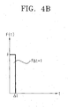
- the response characteristic of the sensing electrode 122 and the sensing gimbals 118 by the application of the Y-axis direction impulse approximates the response characteristic of a 1-degree-of-freedom system having a mass M , spring constant k , and a damping coefficient c , as shown in FIG. 4A.
- the response characteristic of the sensing electrode 122 and the sensing gimbals 188 due to the Y-axis direction impulse is expressed as the resonant frequency
- the relative position of the sensing electrode 122 and the sensing gimbals 118 remains constant even when a Y-axis direction impulse is applied thereto.
- the response characteristic of the first and the second systems is similarly identical.
- the sensing gimbals 118 and the sensing electrode 122 with different shapes and volumes would have different damping coefficients c in an atmospheric environment. Once being packed in a vacuum, however, the damping coefficients c of the sensing gimbals 118 and the sensing electrode 122 are only influenced by the damping property of the material forming the same. As a result, the damping coefficients c of the sensing gimbals 118 and the sensing electrode 122 are almost equal to each other.
- the movable sensing electrode 122 which is movably secured in the wafer 111, and the fact that the sensing gimbals 118 and the sensing electrode 122 have the same displacement with respect to the external impulse, detection of a signal due to the external impulse can be prevented.
- microgyroscope 100 constructed as above according to the present invention will be described below.
- the oscillating gimbals 112 and the sensing gimbals 118 are oscillated in the X-axis direction with resonant frequency f a due to the electrostatic force between the oscillating and driving combs 114 and 117, respectively, and the oscillating direction elastic body 113.
- the oscillating gimbals 112 and the sensing gimbals 118 are subject to the Coriolis force in the Y-axis direction, and accordingly, the sensing gimbals 118 are oscillated by the sensing direction elastic body 119 in the Y-axis direction.
- the sensing combs 120 of the sensing gimbals 118 are displaced relative to the electrode combs 121 of the sensing electrodes 122.
- an electric capacitance between the sensing combs and the electrode combs 120 and 121, respectively varies. Accordingly, the variation of a voltage signal is detected as the angular velocity by a circuit (not shown).
- the Y-axis component of the impulse causes only the sensing electrode 122 and the sensing gimbals 118 to displace.
- the response characteristic of the sensing electrode 122 and the sensing gimbals 118 to the Y-axis component of the impulse may be expressed as the identical resonant frequency due to the sensing electrode elastic body 124, displacement of the sensing electrode 122 and the sensing gimbals 118 is identical with respect to each other even with the application of the Y-axis component of the impulse. Accordingly, the electric capacitance between the sensing and electrode combs 120 and 121, respectively, of the sensing electrode 122, and the sensing gimbals 118 is free from the influence of the Y-axis component of the impulse. Thus, sensing of the signal due to the Y-axis component of the impulse is prevented.
- FIG. 5 a microgyroscope 100' according to a first embodiment of the present invention is illustrated.
- the microgyroscope 100' is provided with elongated oscillating gimbals 112', which are formed to float over a wafer 111', to oscillate in a horizontal direction, i.e., in the X-axis direction, a first comb 114' including a plurality of first combs 114a, 114b disposed on upper and lower sides (as shown in FIG.
- a driving electrode unit 116' including four driving electrode units 116a, 116b, 116c, 116d having a plurality of second combs 117a, 117b, 117c, 117d arranged between the first combs 114a, 114b at predetermined intervals to oscillate the oscillating gimbals 112' with the application of a power supply, sensing gimbals 118' arranged in the oscillating gimbals 112' to oscillate together with the oscillating gimbals 112' in a sensing direction, i.e., in a vertical, or Y-axis, direction, a plurality of third combs 120a, 120b arranged on the upper and lower sides (as shown in FIG.
- a sensing electrode unit 122' having a plurality of electrode comb units 121a, 121b arranged between the third combs 120a, 120b at predetermined intervals, and a sensing electrode supporting portion 128' for movably securing the sensing electrode unit 122' with respect to the wafer 111' so that the sensing electrode unit 122' is oscillated in the same direction as the sensing direction of the sensing gimbals 118', i.e., in the Y-axis direction.
- the oscillating gimbals 112' are oscillated in the X-axis direction by an oscillating direction elastic securing portion 113' of a predetermined damping force elastically disposed between the oscillating gimbals 112' and the wafer 111'.
- the oscillating direction elastic securing portion 113' includes four oscillating direction beam elastic bodies 113a, 113b, 113c, 113d arranged in proximity to comers of the oscillating gimbals 112'.
- a comb sensor 126 that senses the vibration of the sensing gimbals 118' in the X-axis direction.
- the comb sensor 126 includes two comb sensing units 126a, 126b having elongated fifth combs 126a', 126b' oppositely formed with respect to the fourth combs 114c, 114d formed on the left and right outer sides of the oscillating gimbals 112', respectively, to prevent the oscillating voltage from transmitting along a route, such as a bottom surface, to the oscillating gimbals 112' and the like, and subsequently interfering with the comb sensor 126 during the oscillation of the first combs 114a, 114b of the oscillating gimbals 112' through the driving electrode units 116a, 116b, 116c, 116d.
- the driving electrode units 116a, 116b, 116c, 116d are constructed to be applied with positive and negative voltages in symmetrical relation with each other so that the positive and negative voltages are counterbalanced when the AC interference voltage generated due to the oscillating voltage is applied to both ends of the respective comb sensing units 126a, 126b.
- it may be constructed such that the positive voltage is applied to the driving electrode units 116a, 116c, while negative voltage is applied to the driving electrode units 116b, 116d. Since the oscillating gimbals 112' are hardly influenced by the level of oscillating voltage, the oscillating gimbals 112' can resonate stably.
- the sensing gimbals 118' are oscillated in the Y-axis direction by a sensing direction elastic securing portion 119' elastically disposed between the sensing gimbals 118' and the oscillating gimbals 112'.
- the sensing direction elastic securing portion 119' includes two sensing direction beam elastic bodies 119a, 119b having a predetermined damping force that are arranged on both sides of the sensing gimbals 118'.
- the sensing electrode unit 122' is constructed of either a positive, or a negative, sensing electrode connected to a positive, or a negative, electrode supporting portion (not shown), and with the application of external impulse, is capable of sensing the displacement of the sensing gimbals 118' in the Y-axis direction by calculating the difference of an electric capacitance between the electrode combs 121a, 121b of the positive, or the negative, sensing electrode 122' and the third combs 120a, 120b of the sensing gimbals 118'.
- the angular velocity signal can be sensed by sensing the voltage signal, which is in proportional relation with the variation of electric capacitance.
- the sensing electrode supporting portion 128' is formed as a sensing electrode beam elastic body that has an anchor or a vertical column 127' secured on the upper surface of the wafer 111' and extended upwardly, and an elastic horizontal beam 124' elastically disposed to connect the both upper sides of the anchor 127' and the sensing electrode unit 122' .
- sensing direction resonant frequency of the sensing electrode unit 122' supported by the sensing electrode beam elastic body 128' is identical to the sensing direction resonant frequency of the sensing gimbals 118' supported by the sensing direction beam elastic bodies 119a, 119b.
- each of the sensing electrode unit 122' and the sensing gimbals 118' under the Y-axis impulse is displaced as much as the other is, and as a result, the electric capacitance between the electrode comb units 121a, 121b of the sensing electrode unit 122' and the third combs 120a, 120b of the sensing gimbals 118' is not influenced by the Y-axis component of the impulse.
- the sensing of a signal due to the Y-axis component of the impulse is prevented.
- microgyroscope 100' constructed as above is almost identical to that of the microgyroscope 100 of FIG. 3 in principle. Accordingly, a description thereof will be omitted.
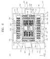
- FIG. 6 a microgyroscope 100" according to a second embodiment of the present invention is illustrated.
- the microgyroscope 100" is similar to the first preferred embodiment of the present invention, as shown in FIG. 5, except that the sensing gimbals 118" are divided into two divisions 118a, 118b, and the sensing electrode unit 122" is arranged in the two divisions 118a, 118b.
- the sensing gimbals 118" are provided with a plurality of third combs 120a', 120b'; 120c, 120d arranged respectively on both upper and lower sides (as shown in FIG. 6) of the respective divisions 118a, 118b in the sensing direction.
- the sensing electrode unit 122" includes first and second sensing electrodes 122a, 122b respectively arranged inside of the divisions 118a, 118b.
- the first and the second sensing electrodes 122a, 122b are provided with a plurality of electrode comb units 121a', 121b'; 121c, 121d arranged between the respective third combs 120a', 120b'; 120c, 120d of the divisions 118a, 118b opposite to the third combs 120a', 120b'; 120c, 120d at predetermined intervals.
- first and the second sensing electrodes 122a, 122b are movably supported on the wafer 111" by the first and the second sensing electrode supporting portions 128", 128"', each being constructed as a sensing electrode beam elastic body that has a vertical column 127", 127''', and an elastic horizontal beam 124", 124''', so as to move in the Y-axis direction.
- the first and the second sensing electrodes 122a, 122b are constructed to be connected with the positive and the negative electrode supporting portions (not shown) to have a positive polarity and a negative polarity. Accordingly, with the application of an external impulse, an electric capacitance of the positive sensing electrode and of the negative sensing electrode varies oppositely to each other, and by the difference of the electric capacitance of the positive and the negative sensing electrodes, the displacement of the sensing gimbals 118" in the Y-axis direction is sensed.
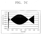
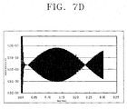
- FIGS. 7B, 7C and 7D illustrate the calculated results of the relation between time and the relative distance of the displacement of the first and the second sensing electrodes 122a, 122b relative to the sensing gimbals 118" according to the resonant frequencies f of the sensing gimbals 118", the electrode comb units 121a', 121b' of the first sensing electrode 122a and the electrode comb units 121c, 121d of the second sensing electrode 122b, when an acceleration impulse of 1 G is applied for 0.01 sec as shown in FIG. 7A.
- FIG. 7B shows the relative distance of the sensing gimbals 118 and the first sensing electrode 122a when the resonant frequency f of the sensing gimbals 118", the resonant frequency f of the electrode comb units 121a', 121b' of the first sensing electrode 122a and the resonant frequency f of the electrode comb units 121c, 121d of the second sensing electrode 122b are equal to each other at 10.32 kHz, which indicates that there is no response to the external acceleration impulse of 1 G.
- FIGS. 7C and 7D illustrate the results when the resonant frequencies f of the sensing gimbals 118'', the electrode comb units 121a', 121b' of the first sensing electrode 122a, and the electrode comb units 121c, 121d of the second sensing electrode 122b are respectively sensed as 10.32 kHz, 10.53 kHz, and 10.37 kHz, and 10.32 kHz, 10.59 kHz, and 10.59 kHz due to fabrication errors.
- FIGS. 7C and 7D although there is an abnormal signal being sensed, it is negligible as compared to the abnormal signals of FIG. 7E that are sensed to the first and the second sensing electrodes 122a, 122b being secured on the wafer 111 " as in the prior art case when impulse of 1 G is applied for 0.01 sec.
- microgyroscope 100" Since the operation of the microgyroscope 100" according to the second preferred embodiment of the present invention is almost identical to that of the microgyroscope of FIG. 3 in principle, a description thereof will be omitted.
- the microgyroscope according to the present invention does not sense unnecessary signals generated due to an external translational acceleration caused by external disturbances, such as noise and impulse.
Landscapes
- Physics & Mathematics (AREA)
- Engineering & Computer Science (AREA)
- General Physics & Mathematics (AREA)
- Radar, Positioning & Navigation (AREA)
- Remote Sensing (AREA)
- Gyroscopes (AREA)
Applications Claiming Priority (2)
| Application Number | Priority Date | Filing Date | Title |
|---|---|---|---|
| KR2002062301 | 2002-10-12 | ||
| KR10-2002-0062301A KR100470590B1 (ko) | 2002-10-12 | 2002-10-12 | 병진 가속에 의한 신호 검출을 방지하기 위한 마이크로자이로스코프 |
Publications (3)
| Publication Number | Publication Date |
|---|---|
| EP1408302A2 true EP1408302A2 (de) | 2004-04-14 |
| EP1408302A3 EP1408302A3 (de) | 2005-10-12 |
| EP1408302B1 EP1408302B1 (de) | 2007-11-14 |
Family
ID=36086259
Family Applications (1)
| Application Number | Title | Priority Date | Filing Date |
|---|---|---|---|
| EP03256281A Expired - Lifetime EP1408302B1 (de) | 2002-10-12 | 2003-10-06 | Für Längsbeschleunigung abstimmbarer Mikrokreisel |
Country Status (7)
| Country | Link |
|---|---|
| US (1) | US6860150B2 (de) |
| EP (1) | EP1408302B1 (de) |
| JP (1) | JP2004132988A (de) |
| KR (1) | KR100470590B1 (de) |
| CN (1) | CN1246668C (de) |
| DE (1) | DE60317436T2 (de) |
| TW (1) | TWI230781B (de) |
Families Citing this family (33)
| Publication number | Priority date | Publication date | Assignee | Title |
|---|---|---|---|---|
| JP3937334B2 (ja) * | 2003-03-27 | 2007-06-27 | 株式会社デンソー | 振動型角速度センサの異常検出装置、異常検出方法、異常検出用プログラム並びに車両制御システム |
| US6880400B1 (en) * | 2003-05-23 | 2005-04-19 | The United States Of America As Represented By The Secretary Of The Navy | Phase synchronized array of non-identical oscillators using coupling network |
| US20050066728A1 (en) * | 2003-09-25 | 2005-03-31 | Kionix, Inc. | Z-axis angular rate micro electro-mechanical systems (MEMS) sensor |
| KR100616641B1 (ko) * | 2004-12-03 | 2006-08-28 | 삼성전기주식회사 | 튜닝포크형 진동식 mems 자이로스코프 |
| US7621183B2 (en) | 2005-11-18 | 2009-11-24 | Invensense Inc. | X-Y axis dual-mass tuning fork gyroscope with vertically integrated electronics and wafer-scale hermetic packaging |
| US20090262074A1 (en) * | 2007-01-05 | 2009-10-22 | Invensense Inc. | Controlling and accessing content using motion processing on mobile devices |
| US8952832B2 (en) | 2008-01-18 | 2015-02-10 | Invensense, Inc. | Interfacing application programs and motion sensors of a device |
| US8250921B2 (en) | 2007-07-06 | 2012-08-28 | Invensense, Inc. | Integrated motion processing unit (MPU) with MEMS inertial sensing and embedded digital electronics |
| US7796872B2 (en) * | 2007-01-05 | 2010-09-14 | Invensense, Inc. | Method and apparatus for producing a sharp image from a handheld device containing a gyroscope |
| US7934423B2 (en) | 2007-12-10 | 2011-05-03 | Invensense, Inc. | Vertically integrated 3-axis MEMS angular accelerometer with integrated electronics |
| US8047075B2 (en) | 2007-06-21 | 2011-11-01 | Invensense, Inc. | Vertically integrated 3-axis MEMS accelerometer with electronics |
| US8020441B2 (en) | 2008-02-05 | 2011-09-20 | Invensense, Inc. | Dual mode sensing for vibratory gyroscope |
| US8141424B2 (en) | 2008-09-12 | 2012-03-27 | Invensense, Inc. | Low inertia frame for detecting coriolis acceleration |
| US8462109B2 (en) * | 2007-01-05 | 2013-06-11 | Invensense, Inc. | Controlling and accessing content using motion processing on mobile devices |
| US8508039B1 (en) | 2008-05-08 | 2013-08-13 | Invensense, Inc. | Wafer scale chip scale packaging of vertically integrated MEMS sensors with electronics |
| CN101563582B (zh) * | 2007-09-19 | 2011-08-24 | 株式会社村田制作所 | 复合传感器及加速度传感器 |
| US7677099B2 (en) * | 2007-11-05 | 2010-03-16 | Invensense Inc. | Integrated microelectromechanical systems (MEMS) vibrating mass Z-axis rate sensor |
| US7755367B2 (en) * | 2008-06-02 | 2010-07-13 | Infineon Technologies, Ag | Silicon MEMS resonators |
| JP5228675B2 (ja) * | 2008-07-29 | 2013-07-03 | 富士通株式会社 | 角速度センサおよび電子装置 |
| DE102008057281A1 (de) * | 2008-11-14 | 2010-05-20 | Northrop Grumman Litef Gmbh | Simulationsverfahren für das Betriebsverhalten eines Corioliskreisels |
| US8534127B2 (en) | 2009-09-11 | 2013-09-17 | Invensense, Inc. | Extension-mode angular velocity sensor |
| US9097524B2 (en) | 2009-09-11 | 2015-08-04 | Invensense, Inc. | MEMS device with improved spring system |
| CN102175236B (zh) * | 2011-02-14 | 2012-12-12 | 厦门大学 | 一种可调整降低正交误差的微陀螺仪 |
| ITTO20110688A1 (it) * | 2011-07-28 | 2013-01-29 | St Microelectronics Srl | Giroscopio microelettromeccanico con funzione di autocalibrazione e metodo di calibrazione di un giroscopio microelettromeccanico |
| US8875578B2 (en) * | 2011-10-26 | 2014-11-04 | Silicon Laboratories Inc. | Electronic damper circuit for MEMS sensors and resonators |
| FI125238B (en) * | 2012-06-29 | 2015-07-31 | Murata Manufacturing Co | Improved vibration gyroscope |
| KR101318421B1 (ko) | 2013-04-08 | 2013-10-16 | 한국생산기술연구원 | 지혈 및 상처치유용 카복시메틸셀룰로오스 폼 및 그의 제조방법 |
| CN205593534U (zh) | 2015-04-24 | 2016-09-21 | 意法半导体股份有限公司 | 微机电陀螺仪和电子系统 |
| KR101679592B1 (ko) * | 2015-05-12 | 2016-11-25 | 주식회사 신성씨앤티 | 대칭형 z축 멤스 자이로스코프 |
| ITUA20162172A1 (it) | 2016-03-31 | 2017-10-01 | St Microelectronics Srl | Sensore accelerometrico realizzato in tecnologia mems avente elevata accuratezza e ridotta sensibilita' nei confronti della temperatura e dell'invecchiamento |
| IT201900017546A1 (it) | 2019-09-30 | 2021-03-30 | St Microelectronics Srl | Dispositivo a pulsante mems resistente all'acqua, dispositivo di ingresso comprendente il dispositivo a pulsante mems e apparecchio elettronico |
| IT202100024644A1 (it) | 2021-09-27 | 2023-03-27 | St Microelectronics Srl | Circuito di controllo di un giroscopio mems, giroscopio mems e metodo di controllo |
| CN115342794B (zh) * | 2022-07-07 | 2026-04-14 | 北京理工大学 | 基于抖动结构的mems陀螺仪及其零偏抑制方法 |
Family Cites Families (7)
| Publication number | Priority date | Publication date | Assignee | Title |
|---|---|---|---|---|
| US5408877A (en) * | 1992-03-16 | 1995-04-25 | The Charles Stark Draper Laboratory, Inc. | Micromechanical gyroscopic transducer with improved drive and sense capabilities |
| DE4442033C2 (de) * | 1994-11-25 | 1997-12-18 | Bosch Gmbh Robert | Drehratensensor |
| KR100211025B1 (ko) * | 1996-12-20 | 1999-07-15 | 정선종 | 진동형 마이크로 자이로스코프 |
| KR100231715B1 (ko) * | 1997-11-25 | 1999-11-15 | 정선종 | 평면 진동형 마이크로 자이로스코프 |
| KR100493149B1 (ko) * | 1999-01-15 | 2005-06-02 | 삼성전자주식회사 | 대칭형 z축 마이크로자이로스코프 및 그 제조방법 |
| KR100363786B1 (ko) * | 1999-05-13 | 2002-12-11 | 삼성전기주식회사 | 마이크로 자이로스코프 |
| KR100363785B1 (ko) * | 1999-06-04 | 2002-12-11 | 삼성전기주식회사 | 마이크로 자이로스코프 |
-
2002
- 2002-10-12 KR KR10-2002-0062301A patent/KR100470590B1/ko not_active Expired - Fee Related
-
2003
- 2003-08-07 US US10/635,471 patent/US6860150B2/en not_active Expired - Lifetime
- 2003-10-06 DE DE60317436T patent/DE60317436T2/de not_active Expired - Lifetime
- 2003-10-06 EP EP03256281A patent/EP1408302B1/de not_active Expired - Lifetime
- 2003-10-10 JP JP2003352772A patent/JP2004132988A/ja active Pending
- 2003-10-10 CN CNB2003101010178A patent/CN1246668C/zh not_active Expired - Fee Related
- 2003-10-13 TW TW092128274A patent/TWI230781B/zh not_active IP Right Cessation
Also Published As
| Publication number | Publication date |
|---|---|
| KR100470590B1 (ko) | 2005-03-08 |
| CN1246668C (zh) | 2006-03-22 |
| TWI230781B (en) | 2005-04-11 |
| KR20040035946A (ko) | 2004-04-30 |
| US6860150B2 (en) | 2005-03-01 |
| CN1497240A (zh) | 2004-05-19 |
| EP1408302A3 (de) | 2005-10-12 |
| US20040069062A1 (en) | 2004-04-15 |
| DE60317436D1 (de) | 2007-12-27 |
| TW200416394A (en) | 2004-09-01 |
| EP1408302B1 (de) | 2007-11-14 |
| DE60317436T2 (de) | 2008-04-17 |
| JP2004132988A (ja) | 2004-04-30 |
Similar Documents
| Publication | Publication Date | Title |
|---|---|---|
| EP1408302B1 (de) | Für Längsbeschleunigung abstimmbarer Mikrokreisel | |
| EP2404139B1 (de) | Vibrierender mikromechanischer winkelgeschwindigkeitssensor | |
| US6742390B2 (en) | Angular velocity sensor | |
| US7191653B2 (en) | Tuning fork vibratory MEMS gyroscope | |
| US8176779B2 (en) | Vibrating micro-mechanical sensor of angular velocity | |
| JP3770677B2 (ja) | マイクロジャイロスコープ | |
| US8453504B1 (en) | Angular rate sensor with suppressed linear acceleration response | |
| CA2663520C (en) | Vibratory gyroscope with parasitic mode damping | |
| US7004024B1 (en) | Horizontal and tuning fork vibratory microgyroscope | |
| US8616057B1 (en) | Angular rate sensor with suppressed linear acceleration response | |
| TWI554741B (zh) | 彈簧結構、諧振器、諧振器陣列與感測器 | |
| US6327907B1 (en) | Microgyroscope having asymmetric comb sensors | |
| JP2008514968A (ja) | 回転速度センサ | |
| EP2592382A1 (de) | Trägheitssensor | |
| EP1472507A1 (de) | Mikrohergestellter kreisel | |
| JP2016507731A (ja) | マイクロメカニカルz軸ジャイロスコープ | |
| JPH11337345A (ja) | 振動するマイクロジャイロメータ | |
| US8459111B1 (en) | Angular rate sensor with suppressed linear acceleration response | |
| US6301963B1 (en) | Microgyroscope having inner and outer mass parts | |
| US6718825B1 (en) | Methods and systems for reducing stick-down within MEMS structures | |
| Soderkvist | Micromachined vibrating gyroscopes | |
| KR100363784B1 (ko) | 마이크로 자이로스코프 | |
| KR20000050760A (ko) | 비대칭 내부 비틀림 짐벌을 가진 측면 구동 방식의 짐벌형 자이로스코프 | |
| KR100491590B1 (ko) | 마이크로 자이로스코프 |
Legal Events
| Date | Code | Title | Description |
|---|---|---|---|
| PUAI | Public reference made under article 153(3) epc to a published international application that has entered the european phase |
Free format text: ORIGINAL CODE: 0009012 |
|
| AK | Designated contracting states |
Kind code of ref document: A2 Designated state(s): AT BE BG CH CY CZ DE DK EE ES FI FR GB GR HU IE IT LI LU MC NL PT RO SE SI SK TR |
|
| AX | Request for extension of the european patent |
Extension state: AL LT LV MK |
|
| RAP1 | Party data changed (applicant data changed or rights of an application transferred) |
Owner name: SAMSUNG ELECTRO-MECHANICS CO. LTD. |
|
| PUAL | Search report despatched |
Free format text: ORIGINAL CODE: 0009013 |
|
| AK | Designated contracting states |
Kind code of ref document: A3 Designated state(s): AT BE BG CH CY CZ DE DK EE ES FI FR GB GR HU IE IT LI LU MC NL PT RO SE SI SK TR |
|
| AX | Request for extension of the european patent |
Extension state: AL LT LV MK |
|
| 17P | Request for examination filed |
Effective date: 20051214 |
|
| AKX | Designation fees paid |
Designated state(s): DE FR GB IT |
|
| GRAP | Despatch of communication of intention to grant a patent |
Free format text: ORIGINAL CODE: EPIDOSNIGR1 |
|
| GRAS | Grant fee paid |
Free format text: ORIGINAL CODE: EPIDOSNIGR3 |
|
| GRAA | (expected) grant |
Free format text: ORIGINAL CODE: 0009210 |
|
| AK | Designated contracting states |
Kind code of ref document: B1 Designated state(s): DE FR GB IT |
|
| REG | Reference to a national code |
Ref country code: GB Ref legal event code: FG4D |
|
| REF | Corresponds to: |
Ref document number: 60317436 Country of ref document: DE Date of ref document: 20071227 Kind code of ref document: P |
|
| ET | Fr: translation filed | ||
| PLBE | No opposition filed within time limit |
Free format text: ORIGINAL CODE: 0009261 |
|
| STAA | Information on the status of an ep patent application or granted ep patent |
Free format text: STATUS: NO OPPOSITION FILED WITHIN TIME LIMIT |
|
| 26N | No opposition filed |
Effective date: 20080815 |
|
| REG | Reference to a national code |
Ref country code: FR Ref legal event code: PLFP Year of fee payment: 13 |
|
| REG | Reference to a national code |
Ref country code: FR Ref legal event code: PLFP Year of fee payment: 14 |
|
| REG | Reference to a national code |
Ref country code: FR Ref legal event code: PLFP Year of fee payment: 15 |
|
| REG | Reference to a national code |
Ref country code: FR Ref legal event code: PLFP Year of fee payment: 16 |
|
| PGFP | Annual fee paid to national office [announced via postgrant information from national office to epo] |
Ref country code: FR Payment date: 20190906 Year of fee payment: 17 |
|
| PGFP | Annual fee paid to national office [announced via postgrant information from national office to epo] |
Ref country code: GB Payment date: 20190909 Year of fee payment: 17 |
|
| PGFP | Annual fee paid to national office [announced via postgrant information from national office to epo] |
Ref country code: DE Payment date: 20190905 Year of fee payment: 17 |
|
| PGFP | Annual fee paid to national office [announced via postgrant information from national office to epo] |
Ref country code: IT Payment date: 20191015 Year of fee payment: 17 |
|
| REG | Reference to a national code |
Ref country code: DE Ref legal event code: R119 Ref document number: 60317436 Country of ref document: DE |
|
| GBPC | Gb: european patent ceased through non-payment of renewal fee |
Effective date: 20201006 |
|
| PG25 | Lapsed in a contracting state [announced via postgrant information from national office to epo] |
Ref country code: DE Free format text: LAPSE BECAUSE OF NON-PAYMENT OF DUE FEES Effective date: 20210501 Ref country code: FR Free format text: LAPSE BECAUSE OF NON-PAYMENT OF DUE FEES Effective date: 20201031 |
|
| PG25 | Lapsed in a contracting state [announced via postgrant information from national office to epo] |
Ref country code: GB Free format text: LAPSE BECAUSE OF NON-PAYMENT OF DUE FEES Effective date: 20201006 |
|
| PG25 | Lapsed in a contracting state [announced via postgrant information from national office to epo] |
Ref country code: IT Free format text: LAPSE BECAUSE OF NON-PAYMENT OF DUE FEES Effective date: 20201006 |