EP1408357A1 - Methode und Vorrichtung zum axialen Ausrichten einer optischen Faser, und Methode und Vorrichtung zum Schmelzspleissen - Google Patents
Methode und Vorrichtung zum axialen Ausrichten einer optischen Faser, und Methode und Vorrichtung zum Schmelzspleissen Download PDFInfo
- Publication number
- EP1408357A1 EP1408357A1 EP20030022699 EP03022699A EP1408357A1 EP 1408357 A1 EP1408357 A1 EP 1408357A1 EP 20030022699 EP20030022699 EP 20030022699 EP 03022699 A EP03022699 A EP 03022699A EP 1408357 A1 EP1408357 A1 EP 1408357A1
- Authority
- EP
- European Patent Office
- Prior art keywords
- optical fiber
- optical fibers
- optical
- butt alignment
- butt
- Prior art date
- Legal status (The legal status is an assumption and is not a legal conclusion. Google has not performed a legal analysis and makes no representation as to the accuracy of the status listed.)
- Granted
Links
Images




Classifications
-
- G—PHYSICS
- G02—OPTICS
- G02B—OPTICAL ELEMENTS, SYSTEMS OR APPARATUS
- G02B6/00—Light guides; Structural details of arrangements comprising light guides and other optical elements, e.g. couplings
- G02B6/24—Coupling light guides
- G02B6/255—Splicing of light guides, e.g. by fusion or bonding
- G02B6/2555—Alignment or adjustment devices for aligning prior to splicing
-
- G—PHYSICS
- G02—OPTICS
- G02B—OPTICAL ELEMENTS, SYSTEMS OR APPARATUS
- G02B6/00—Light guides; Structural details of arrangements comprising light guides and other optical elements, e.g. couplings
- G02B6/24—Coupling light guides
- G02B6/255—Splicing of light guides, e.g. by fusion or bonding
- G02B6/2551—Splicing of light guides, e.g. by fusion or bonding using thermal methods, e.g. fusion welding by arc discharge, laser beam, plasma torch
Definitions
- the present invention relates to an optical fiber axial alignment method and related method for axially aligning one pair of or plural pairs of optical fibers with respect to one another, and an optical fiber fusion splicing method and related device wherein the one pair of or the plural pairs of opposing optical fibers, that are axially aligned, are mutually fusion spliced.
- Fig. 1 shows one embodiment of a related art optical fiber axial alignment and fusion splicing device 101 (hereinafter referred to as "a first related art").
- the optical fiber axial alignment and fusion splicing device 101 is comprised of butt alignment sections 109 having butt alignment V-shaped groove portions 107, respectively, that during positioning of a pair of tape core wires, the tape core wires 105 are caused to butt each other from right and left of the optical fiber axial alignment and fusion splicing device 101, and a pair of optical fiber holder sections 111 (optical fiber holders) that clamp the pair of tape core wires 105, respectively.
- each V-shaped groove portion 107 may be suffice to have at least one groove 107a, since the example of Fig. 1 shows a case where use is made for tape type optical fiber core wires 105 each composed of a plurality of optical fibers 103, butt alignment groove portions 107 are shown as having a plurality of grooves 107a, respectively.
- optical fiber holder sections 111 that clamp the respective optical fibers 103 or the tape core wires 105, are manually shifted, thereby causing the optical fibers 105 to be positioned on the associated V-shaped groove portions 107.
- a worker uses his one hand to move the optical fiber holder section 111 so as to allow all of the optical fibers 103 to be received in the associated grooves 107a of the V-shaped groove section 107 and, if the respective optical fibers 103 are received in the respective grooves 107a, as shown in Figs. 2 and 3, the worker uses the other hand to operate a clamp lever 113 from a condition shown in a dotted line to a condition shown in a solid line, thereby clamping the tape core wire 105 with the optical fiber holder section 111.
- a bottom wall 111a of the optical fiber holder section 111 has asubstantiallyreversedconcaveshape.Meanwhile, aholdersection pedestal 115, on which the optical fiber holder section 111 is rested, has its upper surface formed with a convex portion 115a. A slight degree of gap exists between the convex portion 115a and the bottom wall 111a and moving the optical fiber holder section 111 enables the optical fibers 103 to be precisely positioned in the grooves 107a of the V-shaped groove portion 103.
- a second related art optical fiber axial alignment and fusion splicing device (hereinafter referred to as "a second related art”) has the same V-shaped grooves as those of the first related art set forth above and has the same number of slits, as those of the V-shaped grooves, that protrude above the V-shaped grooves and are fixed rearward of the V-shaped grooves, with the slits and the V-shaped grooves being aligned on the same straight lines. Accordingly, inserting the optical fibers through the slits allows the respective optical fibers to be guided through the slits to fall in parallel to one another and, thus, the optical fibers are easily received in the V-shaped grooves, respectively.
- a distance between the adjacent V-shaped grooves 107 is extremely small to be 0.3 mm and, also, a width of the V-shaped groove 107 per se is extremely narrow to be 0.1 mm. Under such conditions, since the worker needs to carry out positioning between the V-shaped grooves 107 and the optical fibers 103 through hand work, resulting in troublesome issues.
- the second related art optical fiber axial alignment and fusion splicing device due to the need for the optical fibers to be manually positioned when inserting the optical fibers through the slits, a troublesome issue is encountered. Moreover, since the slits are fixed in position, when inserting the optical fibers or removing the optical fibers, if the optical fibers are not moved in a parallel direction, it is highly probable for the optical fibers to be damaged or broken away. For this reason, the worker is required to carry out the work with an extremely high attention and a poor efficiency results in, with a resultant issue arising in a need for worker's skills.
- the present invention has been completedwith a view to addressing the above issues and has an object to provide an optical fiber axial alignment method and related device wherein one pair of or plural pairs of opposing optical fibers are automatically received in butt alignment grooves of the butt alignment section and axially aligned with respect to one another, and an optical fiber fusion splicing method and related device wherein the optical fibers, that are axially aligned, are mutually fusion spliced.
- a first aspect of the present invention is a method of axially aligning at least one pair of opposing optical fibers composed of bare optical fibers, optical fiber strands, unit cores or plural cores of optical fiber core wires, and tape shaped optical fiber core wires, the method comprising: locating optical fiber guide sections, each having at least one guide groove to guide an optical fiber, on both sides of a butt alignment section having a pair of or plural pairs of butt alignment grooves separately formed apart from one another with a given distance in an opposing relationship on a substantially straight line; shifting the optical fiber guide sections at the both sides upward above the butt alignment section and guiding the optical fibers in the guide grooves of the optical fiber guide sections at the both sides under a condition in that distal ends of the optical fibers protrude at least in length to reach the butt alignment grooves of the butt alignment section; and lowering the optical fiber guide sections at the both sides to areas below the butt alignment section to allow the optical fibers to be received in the opposing butt alignment grooves of the butt
- a second aspect of the present invention is an optical fiber axial alignment device for axially aligning at least one pair of opposing optical fibers composed of bare optical fibers, optical fiber strands, unit cores or plural cores of optical fiber core wires, and tape shaped optical fiber core wires, the optical fiber axial alignment device comprising: a butt alignment section having at least one pair of butt alignment grooves formed apart from one another with a given distance in an opposing relationship on a substantially straight line; and optical fiber guide sections, each having at least one pair of guide grooves, and disposed on both sides of the butt alignment section to be moveable in a vertical direction.
- optical fibers generally cover and are referred to bare optical fibers, optical fiber strands, optical fiber cores (in the form of a unit core or multiple cores) and tape type optical fiber cores (composed of a plurality of unit core optical fibers).
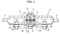
- an optical fiber fusion splicing device 1 of the presently filed embodiment is comprised of a butt alignment section 9 having butt alignment groove sections 7 (show in Figs.5, 6), each of which when aligning a pair of tape core wires 5 each composed of a plurality of bare fibers 3, allows opposing ends of the bare optical fibers 3 to be mutually brought into abutting engagement with respect to one another from right and left sides of the fusion splicing device 1, and optical fiber holder sections 11 (optical fiber holders) to allow the pair of tape core wires 5 to be positioned at both sides of the butt alignment section 9 to be held in position, respectively.
- the butt alignment groove section 7 includes at least one groove 7a(shown in Fig.6).
- each of the tape core wires 5 is constructed of the plurality of bare optical fibers 3 placed parallel to one another and sheathed by a sheath material 13, such as plastic resin, in a tape form.
- a sheath material 13 such as plastic resin
- the sheath material 13 is removed from a distal end of the tape core wire 5 to allow the bare optical fibers 3 to be bared.
- respective bare optical fibers 3 are simply referred to as "optical fibers 3".
- the above-described butt alignment section 9 has a substantially rectangular shape and, as shown in Figs. 5 and 6, has a lateral groove 15, extending in a widthwise direction (in a vertical direction in Fig. 5) formed at a substantially center of a lengthwise direction.
- Plural grooves 7a of the butt alignment groove sections 7 are formed on upper surfaces of a block at both sides of the lateral groove 15 so as to extend in a fore and aft direction (in a left and right direction in Fig. 5) to accommodate and position the optical fibers 3 of the above-described tape core wires 5 (see Figs. 6 and 7).
- the mutually opposing plural groove sections 7 allow centers of the respective optical fibers 3 to be positioned in straight lines when the optical fibers 3 are accommodated in the respective grooves 7a.
- optical fiber fusion means 17 are mounted on both sides of the lateral groove 15 at upper and lower positions thereof in Fig. 5 to fusion splice the optical fibers 3, that are mutually butted in the butt alignment section 9, with respect to one another.
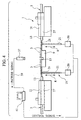
- optical fiber alignment units 19 are examples, that form essential parts of the presently filed embodiment, of the optical fiber axial alignment device. As shown in Figs. 4 to 6, the optical fiber alignment units 19 are mounted for elevating capabilities between the optical fiber holder sections 11 and the butt alignment section 9 so as to allow plate-like optical fiber guide sections 21 to protrude above the position of the butt alignment groove portions 7 of the butt alignment section 9. That is, the optical fiber guide sections 21 have elevating capabilities in directions R as shown by arrows in Fig. 4.
- an upper portion of the optical fiber guide section 21 is formed with a guide groove portion 23 and grooves 23a.
- the guide groove portion 23 is structured such that, when the optical fibers 3 are placed on the associated grooves 23a, the centers of the optical fibers 3 are aligned on the straight lines connecting the centers of optical fibers 3 placed on the grooves 7a of the butt alignment groove portions 7 shown in Fig. 7. For this reason, each of the butt alignment groove portions 7 has the same pitch, i.e., in the same dimension C, as that of each guide groove portion 23.
- an opening portion of each guide groove 23a has a size (a groove width B) greater (wider) than a size (a groove width A (see Fig. 7)) of an opening portion of each groove 7a of the butt alignment groove portions 7.
- a bottom wall 11a of the optical fiber holder section 11 has a concave shape, and an upper surface 27a, that serves as a surface on which the optical fiber holder section 11 is rested, of a holder section pedestal 27 has a convex shape.
- the concave shape of the optical fiber holder section 11 defines a holder guide groove 29 that has the substantially same width as that of the tape core wire 5 (not shown in Fig. 9) such that the optical fiber, i.e., the tape core wire 5 is precisely positioned at a given position.
- the concave shape of the optical fiber holder section 11 and the convex shape of the holder pedestal 27 are brought into mating engagement with no clearance to allow the tape core wire 5 to be precisely clamped in upward and downward directions.
- mounting two magnets 31, 31 on the optical fiber holder section 11 and the holder pedestal 27, respectively, to allow these components to attract each other provides a core urging mechanism 33 (a core urging means) to cause the concave portion of the optical fiber holder section 11 to be attracted by the convex portion of the holder section pedestal 27.
- a mechanism that allows the optical fiber holder section 11 to be held by the holder section pedestal 27 is similar to that shown in Figs. 2 and 3 as previously set forth above. That is, as shown in Fig. 5, operating clamp levers 35 allows the optical fiber holder section 11 to urge the holder section pedestal 27 such that the optical fiber is held between these components.
- the optical fiber alignment device 19 is configured such that an image pick up means (such as a CCD camera 37) for picking up an aligned status of the optical fibers 3 on the butt alignment groove portions (shown in Figs.5, 6) of the butt alignment section 9 is vertically located above the butt alignment groove portions of the butt alignment section 9.
- a picture signal detected by the CCD camera 37 is transmitted to an image analyzer unit 41 (computer) through a camera cable 39.
- the image analyzer unit 41 performs image processing for judging an acceptability of the aligned status of the optical fibers 3 on the butt alignment groove portions.
- the respective tape core wires 5 are positioned by the optical fiber holder section 11 to cause the distal ends of the optical fibers 3 of the pair of tape core wires 5 to be mutually butted. Additionally, since the tape core wire 5 is vertically held in pressured contact with between the bottom wall 11a of the holder section 11 and the upper surface 27a of the pedestal 27, the tape core wire 5 is tightly held between the bottom wall 11a and the upper surface 27a of the pedestal 27 and precisely positioned in the lengthwise direction.
- the optical fiber guide section 21 When permitting the optical fiber holder section 111 to hold the optical fiber, as shown at P in Fig. 10, even if the distal end of the optical fiber 3 is deviated from the associated groove 7a of the butt alignment groove portion 7 of the butt alignment section 9, the optical fiber guide section 21 is elevated to lift the relevant optical fiber 3 once whereby the relevant optical fiber 3 is easily aligned in the associated guide groove 23a of the guide groove portion 23 of the optical fiber guide section 21. Subsequently, lowering the optical fiber guide section 21 with the relevant optical fiber 3 in such an aligned position allows the distal end of the relevant optical fiber 3 to be automatically and reliably received in the associated groove 7a of the butt alignment groove portion 7.
- the distal ends of the optical fibers 3 of the pair of tape core wires 5 are coaxially aligned in a mutually butting engagement. Thereafter, the butted optical fibers 3 are fusion spliced by the fusion splicing means 17.
- the aligned status of the optical fibers 3 on the respective grooves 7a of the butt alignment groove portion 7 is detected by the CCD camera 37.
- the picture signal of the CCD camera 37 is transmitted to the image analyzer unit 41 via the camera cable 39 and, as a result of the received picture signal being analyzed by the image analyzer unit 41, if it is detected that the aligned status of the optical fibers 3 does not satisfy a given condition, that is, when the optical fibers 3 are not properly placed in the associated grooves 7a, a driver section 50 for driving the optical fiber guide section 21 automatically elevates the optical fiber guide section 21 to aposition above the butt alignment section 9 in response to the control signal from the image analyzer unit 41, thereby causing the respective optical fibers 3 to be guided in the respective grooves 23a of the guide groove portion 23 of the optical fiber guide section 21.
- two driver sections in compliance with the number of pieces of the optical fiber guide sections 21 have been shown, a single driver section or other embodiments may be configured so as to achieve similar control.
- the optical fiber guide section 21 is lowered, and the respective optical fibers 3 are received in the grooves 7a of the opposing butt alignment groove portions 7 of the butt alignment section 9, respectively, to axially aligned.
- the optical fibers 3 are brought into alignment in the respectively associated grooves 7a of the given butt alignment groove portions 7 in a further reliable and easy fashion.
- optical fiber fusion splicing device 1 has the same structure as that of the embodiment set forth above, and a detail of the same component parts is omitted.
- the optical fiber guide sections 21 When butting the optical fibers in a manner as set forth above, while the optical fiber guide sections 21 are preliminarily lowered whereupon, after a pair of tape core wires 5 are clamped by the optical fiber holder section 11, the optical fiber guide sections 21 are elevated to raise the optical fibers 3 once for alignment and, then, the optical fiber guide sections 21 are lowered to allow the distal ends of the optical fibers 3 to be received in the respective grooves 7a of the butt alignment groove portions 7, another method may be carried out to obtain the same advantageous effects as those set forth above with a structure wherein the optical fiber sections 21 are caused to be elevated to respective positions higher than the butt alignment groove portions 7 from an initial stage whereupon a pair of tape core wires 5 are clamped by the optical fiber holder section 11 to allow the respective optical fibers 3 to be placed and aligned in the guide grooves 23 of the optical fiber guide sections 21 and, subsequently, the optical fiber guide sections 21 are lowered.
- positions of the optical fiber guide sections 21 in the fore and aft direction lie in substantially intermediate positions between the butt alignment sections 9 and the optical fiber holder sections 11 as shown in Fig. 4, the optical fiber guide sections 21 may be placed near the sheaths of the optical fibers 3 as close as possible such that, even if the distal ends of the optical fibers 3 are widened or subjected to bending at a alight degree, the optical fibers 3 has relatively less spreading or bending at areas in the vicinities of the covered sheath materials 13.
- the optical fibers 3 may be brought into alignment with the guide groove portions 23(shown in Fig.6) of the optical fiber guide section 21 that is elevated once, the spreading and bending of the optical fibers may corrected. Thereafter, lowering the optical fiber guide sections 21 while maintaining the optical fibers 3 in such conditions enables the respective optical fibers 3 to be received in the associated grooves 7a of the butt alignment groove portions 7(shown in Fig.7).
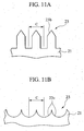
- each groove 23a of the guide groove portion 23 is shown to have a V-shape (the groove 23a shown in Fig. 8) in the embodiment set forth above, the shape of each groove 23a may take the form of configurations such as 23b, 23c shown in Figs. 11A and 11B or may take any other configurations provided that the pitch C of the adjacent grooves 23a is identical in dimension to the pitch C of the above-described grooves 23a, resulting in a capability of obtaining similar advantageous effects provided that the grooves have shapes to accommodate the optical fibers.
- the respective optical fibers 3 are deviated from the associated grooves 7a under the condition in which the tape core wires 5 are clamped by the optical fiber holder sections 11, in a subsequent stage, the respective optical fibers 3 are automatically and easily aligned by the optical fiber guide sections 21.
- optical fiber guide sections movable in the elevated and lowered positions to allow the optical fibers 3 to be automatically aligned after the optical fibers 3 have been set by the optical fiber holder section 11
- no troublesome work is required for preliminarily positioning the optical fibers 3 in the associates slits as required in the related art practice, and the optical fibers can be efficiently positioned in a given position.
- the present invention is not limited to the embodiment set forth above and may take suitable modification to be carried out in other embodiments. While in the optical fiber axial alignment device 19 and the fusion splicing device 1, one piece of optical fiber guide section 21 is located at each of both sides of the butt alignment section 9, it is not objectionable for plural pieces of optical fiber guide sections 24 may be located on both sides of the butt alignment section 9 in a given distance with respect to one another in another embodiment. In such case, the plural pieces of the optical fiber guide sections 21 serve to allow the respective optical fibers 3 to be received in the associated guide groove portions 23 in a further reliable fashion.
Landscapes
- Physics & Mathematics (AREA)
- Engineering & Computer Science (AREA)
- Plasma & Fusion (AREA)
- General Physics & Mathematics (AREA)
- Optics & Photonics (AREA)
- Mechanical Coupling Of Light Guides (AREA)
Applications Claiming Priority (4)
| Application Number | Priority Date | Filing Date | Title |
|---|---|---|---|
| JP2002295120 | 2002-10-08 | ||
| JP2002295120 | 2002-10-08 | ||
| JP2003055753 | 2003-03-03 | ||
| JP2003055753A JP3745340B2 (ja) | 2002-10-08 | 2003-03-03 | 光ファイバの軸合わせ方法及びその装置、並びに光ファイバの融着接続方法及びその装置 |
Publications (2)
| Publication Number | Publication Date |
|---|---|
| EP1408357A1 true EP1408357A1 (de) | 2004-04-14 |
| EP1408357B1 EP1408357B1 (de) | 2011-02-09 |
Family
ID=32032948
Family Applications (1)
| Application Number | Title | Priority Date | Filing Date |
|---|---|---|---|
| EP03022699A Expired - Lifetime EP1408357B1 (de) | 2002-10-08 | 2003-10-07 | Methode und Vorrichtung zum axialen Ausrichten einer optischen Faser, und Methode zum Schmelzspleissen |
Country Status (3)
| Country | Link |
|---|---|
| US (1) | US7151877B2 (de) |
| EP (1) | EP1408357B1 (de) |
| JP (1) | JP3745340B2 (de) |
Families Citing this family (8)
| Publication number | Priority date | Publication date | Assignee | Title |
|---|---|---|---|---|
| JP2005352168A (ja) | 2004-06-10 | 2005-12-22 | Fujikura Ltd | 光ファイバの整列方法、光ファイバの突き合わせ装置および光ファイバの融着接続装置 |
| JP4115454B2 (ja) * | 2005-02-21 | 2008-07-09 | 古河電気工業株式会社 | 光ファイバ保持具 |
| JP4509907B2 (ja) * | 2005-10-03 | 2010-07-21 | 株式会社フジクラ | 光ファイバ端面検査工具 |
| EP3117250A4 (de) * | 2014-03-14 | 2017-10-04 | AFL Telecommunications LLC | Verfahren zur herstellung von fasern mit gebogener spitze |
| CN108896273B (zh) * | 2018-05-04 | 2020-11-20 | 秦昊烨 | 光纤测试压接连接装置及光纤压接连接方法 |
| CN111465880B (zh) * | 2019-09-16 | 2022-01-28 | 四川灼识科技股份有限公司 | 光纤熔接机 |
| WO2022192274A1 (en) * | 2021-03-08 | 2022-09-15 | Commscope Technologies Llc | Bare optical fiber alignment system and device |
| CN117642663A (zh) * | 2021-08-05 | 2024-03-01 | 住友电气工业株式会社 | 熔接机 |
Citations (7)
| Publication number | Priority date | Publication date | Assignee | Title |
|---|---|---|---|---|
| US4102717A (en) | 1975-11-05 | 1978-07-25 | The Post Office | Dielectric optical waveguide couplings |
| JPS59118A (ja) * | 1982-06-25 | 1984-01-05 | Nippon Telegr & Teleph Corp <Ntt> | 多心光フアイバの融着接続機 |
| JPS61112106A (ja) * | 1985-07-26 | 1986-05-30 | Dainichi Nippon Cables Ltd | 光フアイバの融着接続装置 |
| JPS62210406A (ja) * | 1986-03-12 | 1987-09-16 | Fujikura Ltd | 高強度光フアイバの融着接続装置 |
| EP0278423A2 (de) | 1987-02-06 | 1988-08-17 | Sumitomo Electric Industries Limited | Vorrichtung für die Anordnung einer Vielzahl optischer Fasern und Methode für deren gemeinsames Lichtbogenspleissen unter Verwendung dieser Vorrichtung |
| JP2000275462A (ja) * | 1999-03-24 | 2000-10-06 | Fujikura Ltd | 多心光ファイバ整列機構 |
| EP1174744A1 (de) * | 2000-07-21 | 2002-01-23 | Corning Incorporated | Verfahren und Vorrichtung zum Spleissen optischer Fasern |
Family Cites Families (9)
| Publication number | Priority date | Publication date | Assignee | Title |
|---|---|---|---|---|
| US3919037A (en) * | 1974-11-07 | 1975-11-11 | Bell Telephone Labor Inc | Optical fiber splicing apparatus |
| JPS592013A (ja) | 1983-02-23 | 1984-01-07 | Nippon Telegr & Teleph Corp <Ntt> | 光フアイバの案内装置 |
| JPS623208A (ja) * | 1985-06-28 | 1987-01-09 | Sumitomo Electric Ind Ltd | 光フアイバの接続方法 |
| JP2632332B2 (ja) | 1987-12-18 | 1997-07-23 | ヤンマー農機株式会社 | 作業用車両の自動操向装置 |
| US4958905A (en) * | 1989-06-19 | 1990-09-25 | Tynes Arthur R | Method and apparatus for forming high strength splices in optical fibers |
| JP2704338B2 (ja) | 1992-01-10 | 1998-01-26 | 株式会社フジクラ | コネクタフェルールに光ファイバを挿入する装置 |
| SE502879C2 (sv) * | 1994-06-16 | 1996-02-12 | Ericsson Telefon Ab L M | Sätt och anordning för att skarva ihop ändar på optiska fibrer |
| JPH0968622A (ja) | 1995-08-31 | 1997-03-11 | Sumitomo Electric Ind Ltd | 光ファイバ融着接続器 |
| JP3500850B2 (ja) * | 1996-04-23 | 2004-02-23 | 住友電気工業株式会社 | リボン型光ファイバの突き合せ部を観察する方法及び観察装置 |
-
2003
- 2003-03-03 JP JP2003055753A patent/JP3745340B2/ja not_active Expired - Fee Related
- 2003-09-12 US US10/660,691 patent/US7151877B2/en not_active Expired - Fee Related
- 2003-10-07 EP EP03022699A patent/EP1408357B1/de not_active Expired - Lifetime
Patent Citations (7)
| Publication number | Priority date | Publication date | Assignee | Title |
|---|---|---|---|---|
| US4102717A (en) | 1975-11-05 | 1978-07-25 | The Post Office | Dielectric optical waveguide couplings |
| JPS59118A (ja) * | 1982-06-25 | 1984-01-05 | Nippon Telegr & Teleph Corp <Ntt> | 多心光フアイバの融着接続機 |
| JPS61112106A (ja) * | 1985-07-26 | 1986-05-30 | Dainichi Nippon Cables Ltd | 光フアイバの融着接続装置 |
| JPS62210406A (ja) * | 1986-03-12 | 1987-09-16 | Fujikura Ltd | 高強度光フアイバの融着接続装置 |
| EP0278423A2 (de) | 1987-02-06 | 1988-08-17 | Sumitomo Electric Industries Limited | Vorrichtung für die Anordnung einer Vielzahl optischer Fasern und Methode für deren gemeinsames Lichtbogenspleissen unter Verwendung dieser Vorrichtung |
| JP2000275462A (ja) * | 1999-03-24 | 2000-10-06 | Fujikura Ltd | 多心光ファイバ整列機構 |
| EP1174744A1 (de) * | 2000-07-21 | 2002-01-23 | Corning Incorporated | Verfahren und Vorrichtung zum Spleissen optischer Fasern |
Non-Patent Citations (4)
| Title |
|---|
| PATENT ABSTRACTS OF JAPAN vol. 008, no. 082 (P - 268) 14 April 1984 (1984-04-14) * |
| PATENT ABSTRACTS OF JAPAN vol. 010, no. 294 (P - 504) 7 October 1986 (1986-10-07) * |
| PATENT ABSTRACTS OF JAPAN vol. 012, no. 071 (P - 673) 5 March 1988 (1988-03-05) * |
| PATENT ABSTRACTS OF JAPAN vol. 2000, no. 13 5 February 2001 (2001-02-05) * |
Also Published As
| Publication number | Publication date |
|---|---|
| US20040067026A1 (en) | 2004-04-08 |
| JP2004184962A (ja) | 2004-07-02 |
| JP3745340B2 (ja) | 2006-02-15 |
| EP1408357B1 (de) | 2011-02-09 |
| US7151877B2 (en) | 2006-12-19 |
Similar Documents
| Publication | Publication Date | Title |
|---|---|---|
| CN1192257C (zh) | 光纤夹持器、熔合绞接装置切割装置以及光纤绞接方法 | |
| CN100487505C (zh) | 光纤固定器,光纤适配器及具有定位装置的光纤处理设备 | |
| US5395025A (en) | Method and apparatus for angle cleaving ribbon fiber | |
| US7371020B2 (en) | Method of aligning optical-fibers, optical-fiber alignment device, and optical-fiber fusion splicer | |
| EP0803721A2 (de) | Verfahren und Apparat zum Beobachten der Spitze von aneinanderstossenden optischen Fasern | |
| US7151877B2 (en) | Optical fiber axial alignment method and related device, and optical fiber fusion splicing method and related device | |
| JP4098677B2 (ja) | 光ファイバスプライサ及び光ファイバのスプライシング方法 | |
| JP5113344B2 (ja) | 光ファイバホルダ及びその使用方法 | |
| CN114488441B (zh) | 一种光纤跳线单元制造工艺及光电转换模组制造工艺 | |
| US6850686B2 (en) | Machining an insulated optical fiber | |
| CN1250991C (zh) | 光纤轴向对准方法与相关设备,光纤熔接方法与相关设备 | |
| JPS62223708A (ja) | 光フアイバ融着接続装置 | |
| JPS61294403A (ja) | 光フアイバ接続用搬送機構 | |
| KR20240110894A (ko) | 융착 접속기 | |
| KR102763896B1 (ko) | 광 파이버 정렬 지그, 광 파이버 정렬 지그를 구비한 광 파이버 융착 접속기, 및 광 파이버 정렬 방법 | |
| JP2000275462A (ja) | 多心光ファイバ整列機構 | |
| JP3802828B2 (ja) | 光ファイバテープ心線の分離工具 | |
| JPH06214132A (ja) | 光ファイバの配線切替装置 | |
| JP2000147316A (ja) | 光ファイバ突合わせ接続用工具 | |
| JPH06201948A (ja) | 光ファイバテープ心線の簡易接続治具 | |
| JP2000221367A (ja) | 光ファイバ突き合わせ装置 | |
| JPH01121804A (ja) | 光ファイバ端部の位置合わせ装置 | |
| JPH05224072A (ja) | 光ファイバ心線の融着接続機 | |
| JPH09101427A (ja) | 光ファイバ接続装置 | |
| JPH01205108A (ja) | 光ファイバの融着接続装置 |
Legal Events
| Date | Code | Title | Description |
|---|---|---|---|
| PUAI | Public reference made under article 153(3) epc to a published international application that has entered the european phase |
Free format text: ORIGINAL CODE: 0009012 |
|
| 17P | Request for examination filed |
Effective date: 20031007 |
|
| AK | Designated contracting states |
Kind code of ref document: A1 Designated state(s): AT BE BG CH CY CZ DE DK EE ES FI FR GB GR HU IE IT LI LU MC NL PT RO SE SI SK TR |
|
| AX | Request for extension of the european patent |
Extension state: AL LT LV MK |
|
| AKX | Designation fees paid |
Designated state(s): FR GB IT SE |
|
| REG | Reference to a national code |
Ref country code: DE Ref legal event code: 8566 |
|
| 17Q | First examination report despatched |
Effective date: 20080214 |
|
| GRAP | Despatch of communication of intention to grant a patent |
Free format text: ORIGINAL CODE: EPIDOSNIGR1 |
|
| RTI1 | Title (correction) |
Free format text: OPTICAL FIBER AXIAL ALIGNMENT METHOD AND RELATED DEVICE, AND OPTICAL FIBER FUSION SPLICING METHOD |
|
| GRAS | Grant fee paid |
Free format text: ORIGINAL CODE: EPIDOSNIGR3 |
|
| GRAA | (expected) grant |
Free format text: ORIGINAL CODE: 0009210 |
|
| AK | Designated contracting states |
Kind code of ref document: B1 Designated state(s): FR GB IT SE |
|
| REG | Reference to a national code |
Ref country code: GB Ref legal event code: FG4D |
|
| REG | Reference to a national code |
Ref country code: SE Ref legal event code: TRGR |
|
| PLBE | No opposition filed within time limit |
Free format text: ORIGINAL CODE: 0009261 |
|
| STAA | Information on the status of an ep patent application or granted ep patent |
Free format text: STATUS: NO OPPOSITION FILED WITHIN TIME LIMIT |
|
| 26N | No opposition filed |
Effective date: 20111110 |
|
| PGFP | Annual fee paid to national office [announced via postgrant information from national office to epo] |
Ref country code: SE Payment date: 20111018 Year of fee payment: 9 Ref country code: FR Payment date: 20111026 Year of fee payment: 9 |
|
| GBPC | Gb: european patent ceased through non-payment of renewal fee |
Effective date: 20121007 |
|
| REG | Reference to a national code |
Ref country code: FR Ref legal event code: ST Effective date: 20130628 |
|
| PG25 | Lapsed in a contracting state [announced via postgrant information from national office to epo] |
Ref country code: SE Free format text: LAPSE BECAUSE OF NON-PAYMENT OF DUE FEES Effective date: 20121008 Ref country code: GB Free format text: LAPSE BECAUSE OF NON-PAYMENT OF DUE FEES Effective date: 20121007 |
|
| PG25 | Lapsed in a contracting state [announced via postgrant information from national office to epo] |
Ref country code: IT Free format text: LAPSE BECAUSE OF NON-PAYMENT OF DUE FEES Effective date: 20121007 Ref country code: FR Free format text: LAPSE BECAUSE OF NON-PAYMENT OF DUE FEES Effective date: 20121031 |