EP1408683B1 - Procédé et appareil pour la réduction de faux contours dans panneaux d'affichages avec modulation du nombre d'impulsions - Google Patents
Procédé et appareil pour la réduction de faux contours dans panneaux d'affichages avec modulation du nombre d'impulsions Download PDFInfo
- Publication number
- EP1408683B1 EP1408683B1 EP03255189A EP03255189A EP1408683B1 EP 1408683 B1 EP1408683 B1 EP 1408683B1 EP 03255189 A EP03255189 A EP 03255189A EP 03255189 A EP03255189 A EP 03255189A EP 1408683 B1 EP1408683 B1 EP 1408683B1
- Authority
- EP
- European Patent Office
- Prior art keywords
- pixel
- gray
- level
- current frame
- image signal
- Prior art date
- Legal status (The legal status is an assumption and is not a legal conclusion. Google has not performed a legal analysis and makes no representation as to the accuracy of the status listed.)
- Expired - Lifetime
Links
Images





Classifications
-
- G—PHYSICS
- G09—EDUCATION; CRYPTOGRAPHY; DISPLAY; ADVERTISING; SEALS
- G09G—ARRANGEMENTS OR CIRCUITS FOR CONTROL OF INDICATING DEVICES USING STATIC MEANS TO PRESENT VARIABLE INFORMATION
- G09G3/00—Control arrangements or circuits, of interest only in connection with visual indicators other than cathode-ray tubes
- G09G3/20—Control arrangements or circuits, of interest only in connection with visual indicators other than cathode-ray tubes for presentation of an assembly of a number of characters, e.g. a page, by composing the assembly by combination of individual elements arranged in a matrix no fixed position being assigned to or needed to be assigned to the individual characters or partial characters
- G09G3/22—Control arrangements or circuits, of interest only in connection with visual indicators other than cathode-ray tubes for presentation of an assembly of a number of characters, e.g. a page, by composing the assembly by combination of individual elements arranged in a matrix no fixed position being assigned to or needed to be assigned to the individual characters or partial characters using controlled light sources
- G09G3/28—Control arrangements or circuits, of interest only in connection with visual indicators other than cathode-ray tubes for presentation of an assembly of a number of characters, e.g. a page, by composing the assembly by combination of individual elements arranged in a matrix no fixed position being assigned to or needed to be assigned to the individual characters or partial characters using controlled light sources using luminous gas-discharge panels, e.g. plasma panels
- G09G3/288—Control arrangements or circuits, of interest only in connection with visual indicators other than cathode-ray tubes for presentation of an assembly of a number of characters, e.g. a page, by composing the assembly by combination of individual elements arranged in a matrix no fixed position being assigned to or needed to be assigned to the individual characters or partial characters using controlled light sources using luminous gas-discharge panels, e.g. plasma panels using AC panels
- G09G3/296—Driving circuits for producing the waveforms applied to the driving electrodes
-
- G—PHYSICS
- G09—EDUCATION; CRYPTOGRAPHY; DISPLAY; ADVERTISING; SEALS
- G09G—ARRANGEMENTS OR CIRCUITS FOR CONTROL OF INDICATING DEVICES USING STATIC MEANS TO PRESENT VARIABLE INFORMATION
- G09G3/00—Control arrangements or circuits, of interest only in connection with visual indicators other than cathode-ray tubes
- G09G3/20—Control arrangements or circuits, of interest only in connection with visual indicators other than cathode-ray tubes for presentation of an assembly of a number of characters, e.g. a page, by composing the assembly by combination of individual elements arranged in a matrix no fixed position being assigned to or needed to be assigned to the individual characters or partial characters
- G09G3/2007—Display of intermediate tones
- G09G3/2059—Display of intermediate tones using error diffusion
-
- G—PHYSICS
- G09—EDUCATION; CRYPTOGRAPHY; DISPLAY; ADVERTISING; SEALS
- G09G—ARRANGEMENTS OR CIRCUITS FOR CONTROL OF INDICATING DEVICES USING STATIC MEANS TO PRESENT VARIABLE INFORMATION
- G09G3/00—Control arrangements or circuits, of interest only in connection with visual indicators other than cathode-ray tubes
- G09G3/20—Control arrangements or circuits, of interest only in connection with visual indicators other than cathode-ray tubes for presentation of an assembly of a number of characters, e.g. a page, by composing the assembly by combination of individual elements arranged in a matrix no fixed position being assigned to or needed to be assigned to the individual characters or partial characters
- G09G3/2007—Display of intermediate tones
- G09G3/2018—Display of intermediate tones by time modulation using two or more time intervals
- G09G3/2022—Display of intermediate tones by time modulation using two or more time intervals using sub-frames
-
- G—PHYSICS
- G09—EDUCATION; CRYPTOGRAPHY; DISPLAY; ADVERTISING; SEALS
- G09G—ARRANGEMENTS OR CIRCUITS FOR CONTROL OF INDICATING DEVICES USING STATIC MEANS TO PRESENT VARIABLE INFORMATION
- G09G2320/00—Control of display operating conditions
- G09G2320/02—Improving the quality of display appearance
- G09G2320/0266—Reduction of sub-frame artefacts
-
- G—PHYSICS
- G09—EDUCATION; CRYPTOGRAPHY; DISPLAY; ADVERTISING; SEALS
- G09G—ARRANGEMENTS OR CIRCUITS FOR CONTROL OF INDICATING DEVICES USING STATIC MEANS TO PRESENT VARIABLE INFORMATION
- G09G2320/00—Control of display operating conditions
- G09G2320/02—Improving the quality of display appearance
- G09G2320/0271—Adjustment of the gradation levels within the range of the gradation scale, e.g. by redistribution or clipping
- G09G2320/0276—Adjustment of the gradation levels within the range of the gradation scale, e.g. by redistribution or clipping for the purpose of adaptation to the characteristics of a display device, i.e. gamma correction
-
- G—PHYSICS
- G09—EDUCATION; CRYPTOGRAPHY; DISPLAY; ADVERTISING; SEALS
- G09G—ARRANGEMENTS OR CIRCUITS FOR CONTROL OF INDICATING DEVICES USING STATIC MEANS TO PRESENT VARIABLE INFORMATION
- G09G2320/00—Control of display operating conditions
- G09G2320/10—Special adaptations of display systems for operation with variable images
- G09G2320/103—Detection of image changes, e.g. determination of an index representative of the image change
-
- G—PHYSICS
- G09—EDUCATION; CRYPTOGRAPHY; DISPLAY; ADVERTISING; SEALS
- G09G—ARRANGEMENTS OR CIRCUITS FOR CONTROL OF INDICATING DEVICES USING STATIC MEANS TO PRESENT VARIABLE INFORMATION
- G09G2340/00—Aspects of display data processing
- G09G2340/16—Determination of a pixel data signal depending on the signal applied in the previous frame
-
- G—PHYSICS
- G09—EDUCATION; CRYPTOGRAPHY; DISPLAY; ADVERTISING; SEALS
- G09G—ARRANGEMENTS OR CIRCUITS FOR CONTROL OF INDICATING DEVICES USING STATIC MEANS TO PRESENT VARIABLE INFORMATION
- G09G3/00—Control arrangements or circuits, of interest only in connection with visual indicators other than cathode-ray tubes
- G09G3/20—Control arrangements or circuits, of interest only in connection with visual indicators other than cathode-ray tubes for presentation of an assembly of a number of characters, e.g. a page, by composing the assembly by combination of individual elements arranged in a matrix no fixed position being assigned to or needed to be assigned to the individual characters or partial characters
- G09G3/2007—Display of intermediate tones
- G09G3/2077—Display of intermediate tones by a combination of two or more gradation control methods
-
- G—PHYSICS
- G09—EDUCATION; CRYPTOGRAPHY; DISPLAY; ADVERTISING; SEALS
- G09G—ARRANGEMENTS OR CIRCUITS FOR CONTROL OF INDICATING DEVICES USING STATIC MEANS TO PRESENT VARIABLE INFORMATION
- G09G3/00—Control arrangements or circuits, of interest only in connection with visual indicators other than cathode-ray tubes
- G09G3/20—Control arrangements or circuits, of interest only in connection with visual indicators other than cathode-ray tubes for presentation of an assembly of a number of characters, e.g. a page, by composing the assembly by combination of individual elements arranged in a matrix no fixed position being assigned to or needed to be assigned to the individual characters or partial characters
- G09G3/22—Control arrangements or circuits, of interest only in connection with visual indicators other than cathode-ray tubes for presentation of an assembly of a number of characters, e.g. a page, by composing the assembly by combination of individual elements arranged in a matrix no fixed position being assigned to or needed to be assigned to the individual characters or partial characters using controlled light sources
- G09G3/28—Control arrangements or circuits, of interest only in connection with visual indicators other than cathode-ray tubes for presentation of an assembly of a number of characters, e.g. a page, by composing the assembly by combination of individual elements arranged in a matrix no fixed position being assigned to or needed to be assigned to the individual characters or partial characters using controlled light sources using luminous gas-discharge panels, e.g. plasma panels
- G09G3/288—Control arrangements or circuits, of interest only in connection with visual indicators other than cathode-ray tubes for presentation of an assembly of a number of characters, e.g. a page, by composing the assembly by combination of individual elements arranged in a matrix no fixed position being assigned to or needed to be assigned to the individual characters or partial characters using controlled light sources using luminous gas-discharge panels, e.g. plasma panels using AC panels
Definitions
- the present invention relates to a method and apparatus for reducing false contour in a digital display apparatus including a plasma display panel using pulse number modulation.
- FIG. 1 illustrates an illuminating method used in PDPs.
- the horizontal axis indicates time, and the vertical axis indicates the number of horizontal scan lines.
- One field is divided into a plurality of subfields, and each subfield is divided into an address period and a sustain period.
- a PDP cell is discharged using a sustain pulse so that the sustain period is maintained for a period of time corresponding to a luminance weight depending on a gray level of an input image, and the gray level of image information is displayed by selectively combining the subfields.
- FIG. 2 shows an example of occurrence of false contour.
- One frame is composed of 8 subfields, and subfields have a luminance weight ratio of 1:2:4:8:16:32:64:128 and gray levels of 127 (pixel A) and 128 (pixel B).
- a gray level integrated on the human retina is expressed through the integration of subfields in the time direction. Accordingly, when there is a great difference in the emission pattern of a subfield at the same position due to, for example, a motion in a moving image, a gray level having a completely different brightness value than the brightness value of an original input pixel is spatially perceived by the retina, thereby provoking false contour.
- subfields are arranged in substantially increasing or decreasing order of luminance weights, and a subfield combination minimizing the number of subfields with large luminance weights that are "on” is selected out of subfield combinations for which displaying a gray level is possible, thereby reducing occurrences of false contour.
- a change in "on/off" subfield diffusion is temporally dispersed, thereby reducing occurrences of false contour.
- false contour cannot be efficiently eliminated.
- a large motion causes an error to be large, and thus noise is easily perceived due to error diffusion.
- EP 0973147 discloses a method of reducing false contour in which a moved direction and a moved quantity of an image are first detected. New image data is then generated, based on the image movement information, which provides a tone received by a retina.
- EP 0822536 discloses a method of reducing false contour in which a position of a halftone image on a display device is changed from subframe to subframe in each frame.
- US 6052491 discusses methods of reducing false contouring of the type caused by quantization errors during analogue to digital conversion. This type of false contouring is exhibited by still and moving images alike. The methods include dithering of output values and error diffusion.
- an apparatus for reducing false contour in a digital display panel comprising: a data converter arranged to process an image signal such that a gray level of the image signal exists within a predetermined range; an error diffuser arranged to diffuse an error between a gray level of a current pixel in a current frame of the image signal received from the data converter and a gray level of the current pixel in the current frame after being subjected to gray-level change, to pixels adjacent to the current pixel in the current frame; a first gray level-changing unit arranged to receive the image signal from the error diffuser, calculate a difference in a gray level between each pixel in the current frame of the image signal, hereinafter referred to as the current frame pixel, and a pixel corresponding to the current frame pixel in a previous frame of the image signal, hereinafter referred to as the previous frame pixel, and selectively change the gray level of the current frame pixel based on the gray level difference such that a transition in the emission pattern of
- the subfield converter represents the gray levels of subfields in the image signal with weights D0 through D9 in an increasing order from a lower to a higher value according to a predetermined rule such that highest weights D7, D8, and D9 do not allow emission pattern transition to occur with an increase in the gray level of the image signal, and such that higher weights D3, D4, D5, and D6 allow an off state to have a regular distribution with the increase in the gray level of the image signal.
- the subfield converter may represent the gray levels of subfields in the image signal with weights D0 through D9 in an increasing order from a lower to a higher value according to a predetermined rule such that an emission pattern is changed only at the weights D0, D1, D2, D3, D4, D5, and D6 with a change in the gray level of the image signal.
- the first gray-level changing unit includes a frame memory part, which receives the image signal from the data converter and stores information on a currently input frame as previous frame information for a next input frame; an pixel transition determiner, which receives current frame information of the image signal from the error diffuser and the previous frame information from the frame memory part and determines a degree of gray-level transition between each pixel in the current frame and a corresponding pixel in the previous frame; a still image determiner, which receives the degree of gray-level transition from the pixel transition determiner and determines whether the current frame is a still image based on the degree of gray-level transition and a predetermined level; a pixel group number storage part, which stores pixel group number information regarding to each pixel in the previous frame based on the gray level of the pixel after being subjected to the gray-level change; and a second gray-level changing unit, which when the still image determiner determines the current frame as not a still image, changes the gray level of the current frame according to a predetermined method
- the second gray-level changing unit outputs a gray level of the previous frame when the still image determiner determines the current frame as a still image.
- the pixel transition determiner determines the degree of gray-level transition between a particular pixel in the current frame, i.e., a current frame pixel, and a corresponding pixel in the previous frame, i.e., a previous frame pixel, using an average of gray level of all pixels included in a square block that has a predetermined size and has the current frame pixel at its center, an average of absolute values of the gray levels of all of the pixels included in the square block except for the current frame pixel, an average of absolute values of differences between the gray levels of all of the pixels included in the square block and respective gray levels of all pixels included in a square block that has the predetermined size and has the previous frame pixel at its center, and an absolute value of a difference between the gray level of the current frame pixel and the gray level of the previous frame pixel.
- the still image determiner determines the current frame as a still image when a ratio of the number of pixels, which are determined as having less motion than a predetermined amount in the current frame of the image signal received from the pixel transition determiner, to a total number of pixels in the current frame is greater than the predetermined value.
- the second gray-level changing unit compares the degree of gray-level transition from the pixel transition determiner with a predetermined level and changes the gray level of each pixel in the current frame based on the result of the comparison.
- the second gray-level changing unit compares the degree of gray-level transition from the pixel transition determiner with a predetermined level and when the degree of gray-level transition is lower than the predetermined level and when a pixel group number of a pixel in the current frame, i.e., the current frame pixel, is different from a pixel group number of a corresponding pixel in the previous frame, i.e., the previous frame pixel, changes the pixel group number of the current frame pixel to a pixel group number close to the pixel group number of the previous frame pixel among pixel group numbers adjacent to the pixel group number of the current frame pixel.
- the second gray-level changing unit changes weights representing the gray level of the current frame pixel such that an emission pattern of the current frame is the same as that of the previous frame with respect to the weights D3, D4, and D5.
- the second gray-level changing unit changes weights representing the gray level of the current frame pixel such that a distribution of on states at the weights D3, D4, D5, and D6 is regular in a diagonal direction when the on states of the weights D0 through D9 are arranged in an increasing order of the gray levels.
- a method of reducing false contour in a digital display panel comprising: (a) processing an image signal such that a gray level of the image signal exists within a predetermined range; (b) diffusing an error between a gray level of a current pixel in a current frame of the image signal resulting from step (a) and a gray level of the current pixel in the current frame after being subjected to gray-level change to pixels adjacent to the current pixel in the current frame; (c) calculating a difference in a gray level between each pixel in the current frame of the image signal resulting from step (b), hereinafter referred to as the current frame pixel, and a pixel corresponding to the current frame pixel in a previous frame of the image signal resulting from step (b), and selectively changing the gray level of the current frame pixel based on the gray level difference such that higher weighted subfields, among subfields not all having the same weight and which illuminate according to the gray level of the current frame
- step (d) includes representing the gray levels of subfields in the image signal with weights D0 through D9 in an increasing order from a lower to a higher value according to a predetermined rule such that highest weights D7, D8, and D9 do not allow emission pattern transition to occur with an increase in the gray level of the image signal, and such that higher weights D3, D4, D5, and D6 allow an off state to have a regular distribution with the increase in the gray level of the image signal.
- step (c) includes (c1) storing information on a currently input frame of the image signal resulting from step (a) as previous frame information for a next input frame; (c2) determining a degree of gray-level transition between each pixel in the current frame and a corresponding pixel in the previous frame based on current frame information of the image signal resulting from step (a) and the previous frame information resulting from step (c1); (c3) determining whether the current frame is a still image based on the degree of gray-level transition and a predetermined level; (c4) storing pixel group number information regarding to each pixel in the previous frame based on the gray level of the pixel after being subjected to the gray-level change; and (c5) when the current frame is determined as not a still image, changing the gray level of the current frame according to a predetermined method using the current frame information, the degree of gray-level transition, the previous frame information, and the pixel group number information.
- step (c5) comprises outputting a gray level of the previous frame when the current frame is determined as a still image in step (c3).
- step (c2) comprises determining the degree of gray-level transition between a particular pixel in the current frame, i.e., a current frame pixel, and a corresponding pixel in the previous frame, i.e., a previous frame pixel, using an average of gray level of all pixels included in a square block that has a predetermined size and has the current frame pixel at its center, an average of absolute values of the gray levels of all of the pixels included in the square block except for the current frame pixel, an average of absolute values of differences between the gray levels of all of the pixels included in the square block and respective gray levels of all pixels included in a square block that has the predetermined size and has the previous frame pixel at its center, and an absolute value of a difference between the gray level of the current frame pixel and the gray level of the previous frame pixel.
- step (c3) comprises determining the current frame as a still image, when a ratio of the number of pixels, which are determined as having less motion than a predetermined amount in the current frame of the image signal in step (c2), to a total number of pixels in the current frame is greater than a predetermined value.
- step (c5) comprises comparing the degree of gray-level transition resulting from step (c2) with a predetermined level and changing the gray level of each pixel in the current frame based on the result of the comparison.
- step (c5) comprises comparing the degree of gray-level transition resulting from step (c2) with a predetermined level and when the degree of gray-level transition is lower than the predetermined level and when a pixel group number of a pixel in the current frame, i.e., the current frame pixel, is different from a pixel group number of a corresponding pixel in the previous frame, i.e., the previous frame pixel, changing the pixel group number of the current frame pixel to a pixel group number close to the pixel group number of the previous frame pixel among pixel group numbers adjacent to the pixel group number of the current frame pixel.
- step (c5) comprises changing weights representing the gray level of the current frame pixel such that an emission pattern of the current frame is the same as that of the previous frame with respect to the weights D3, D4, and D5.
- step (c5) comprises changing weights representing the gray level of the current frame pixel such that a distribution of on states at the weights D3, D4, D5, and D6 is regular in a diagonal direction when the on states of the weights D0 through D9 are arranged in an increasing order of the gray levels.
- step (c5) comprises not changing gray levels corresponding to the pixel group numbers 0 and 5.
- the present invention also provides a computer software product arranged to execute the above method.
- an apparatus for driving a digital display panel comprising: an image signal input unit, which separates only an analog image signal from an input composite image signal; an analog-to-digital converter, which converts the analog image signal to a digital image signal; a gamma correction unit, which corrects the digital image signal to suit for the characteristics of a plasma display panel (PDP); a false contour elimination unit, which converts subfields by selectively changing a gray level of the corrected digital image signal depending on a degree of gray-level transition between each current frame pixel and a corresponding previous frame pixel in the image signal so that false contour is reduced; and a display control unit, which displays the subfield-converted image signal received from the false contour elimination unit on the PDP, wherein the false contour elimination unit comprises the apparatus for reducing false contour described above.
- the present invention thus provides a method and apparatus for reducing false contour in a digital display apparatus including a plasma display panel using pulse number modulation.
- the present invention also provides an apparatus for driving a digital display apparatus including a plasma display panel using pulse number modulation and including apparatus for reducing false contour.
- the present invention is provided in order to effectively reduce false contour which inevitably occurs when a flat matrix display apparatus such as a plasma display panel (PDP) displays the gray level of a moving image.
- the present invention configures luminance weights on subfields such that emission pattern transition occurs only at relatively small luminance weights, thereby suppressing the occurrence of false contour, and changes the gray level of a current frame pixel such that the influence of a motion between a previous frame pixel and the current frame pixel, which are located at the same spatial position, on the emission pattern transition of a subfield is minimized, thereby reducing a degree of false contour.
- the error is diffused to peripheral pixels so that and error in a gray level between the input signal and an actually displayed signal is counterbalanced.
- a gray level is adjusted depending on the amount of motion so that an error is small where motion is small. Even if motion is large, since a gray level minimizing the emission pattern transition of relatively higher weighted subfields between a previous frame pixel and a current input pixel exists among gray levels that are adjacent to the gray level of the current input pixel with a small difference therefrom, the degree of perception of diffused noise due to error diffusion is reduced.
- FIG. 3 is a block diagram of an apparatus for driving a PDP according to a preferred embodiment of the present invention.
- An image signal input unit 100 separates only an image signal from an input composite image signal.
- An analog-to-digital (A/D) converter 110 converts the separated analog image signal to a digital image signal.
- a gamma correction unit 120 corrects an image signal, which is configured to be suit to cathode-ray tube (CRT) characteristics, to be suit to PDP characteristics.
- CRT cathode-ray tube
- a false contour elimination unit 130 converts subfields by changing the gray level of an input image signal depending on the amount of motion so that false contour is minimized.
- a display control unit 140 displays the input image signal that have been coded based on subfields on a PDP.
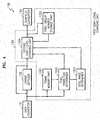
- FIG. 4 is a block diagram of the false contour elimination unit 130 shown in FIG. 3.
- a data converter 131 operates to make input data exist within a predetermined gray-level range.
- An error diffuser 132 diffuses an error to peripheral pixels in order to minimize image distortion due to the error between an original signal and a gray-level changed signal.
- a first gray-level changing unit 133 receives the image signal from the error diffuser 132, obtains a gray-level difference between each pixel in a current frame and the corresponding pixel in a previous frame, changes the gray level of the current frame pixel based on the gray-level difference such that emission pattern transition between current higher weighted subfields and the higher weighted subfields in the previous frame pixel is minimized.
- a subfield converter 134 converts subfields according to the changed gray level.
- the first gray-level changing unit 133 may include an pixel transition determiner 1332, which determines the amount of motion between each pixel in a current frame and the corresponding pixel in a previous frame; a frame memory part 1331, which stores previous frame data; a second gray-level changing unit 1334, which operates to reduce the emission pattern transition of a subfield in units of pixels; a pixel group number storage part 1335, which stores emission pattern information of higher weighted subfields in each previous frame pixel by the spatial positions of previous frame pixels; and a still image determiner 1333, which determines whether an input image signal corresponds to a still image.
- pixel transition determiner 1332 which determines the amount of motion between each pixel in a current frame and the corresponding pixel in a previous frame
- a frame memory part 1331 which stores previous frame data
- a second gray-level changing unit 1334 which operates to reduce the emission pattern transition of a subfield in units of pixels
- a pixel group number storage part 1335 which stores emission pattern information of higher
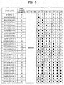
- FIG. 5 is a diagram of a preferred embodiment of an emission pattern in subfield conversion according to the present invention.
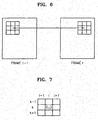
- FIG. 6 is a diagram of a preferred embodiment of the operation of the pixel transition determiner 1332.
- FIG. 7 is a diagram for explaining a preferred embodiment of a mask used for calculating a transition information parameter according to the present invention.
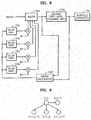
- FIG. 8 is a block diagram of a preferred embodiment of the error diffuser 132 shown in FIG. 3.
- FIG. 9 is a diagram of a preferred embodiment of the application of error diffusion according to the present invention.
- FIG. 10 is a diagram of a preferred embodiment of the continuous on state of a subfield according to the present invention.
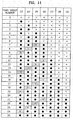
- FIG. 11 is a diagram for explaining transition in higher weighted subfields in each pixel having a different pixel group number according to the present invention.
- FIG. 12 is a diagram for explaining a preferred embodiment of a method of converting a higher weighted subfield according to the present invention.
- FIG. 13 is a diagram for explaining a preferred embodiment of the configuration of pixel group number difference data according to the present invention.
- the gray level of an input image with high luminance may be beyond an expressible gray-level range.
- the data converter 131 converts input data such that an inexpressible gray level can be displayed within the expressible gray-level range in order to display an image without distortion.
- input data can be converted using the gamma correction unit 120 shown in FIG. 3. Since human sight cannot easily identify a high-luminance area, influence of data conversion is not much. Generally, as the number of subfields increases, an inexpressible gray-level portion having high luminance becomes very small. With a small number of subfields, an inexpressible gray-level portion having high luminance is large.
- the pixel transition determiner 1332 determines a degree of gray-level transition between an original pixel in a previous frame stored in the frame memory part 1331 and a current frame pixel.
- the pixel transition determiner 1332 uses difference information between pixels. The result of the determination is used to determine the amount of motion between the corresponding two pixels in the respective previous and current frames and determine whether a current input image is a still image.
- various types of noise exist in an input image. When using only the difference between pixels, the influence of the noise in the input image is large. Accordingly, the present invention uses 3x3 block data to determine the degree of gray-level transition between pixels. In determining the degree of gray-level transition, as shown in FIG.
- a 3x3 block having a current frame pixel at its center and a 3x3 block located at the same spatial position as the 3x3 block having the current frame pixel in a previous frame are used to calculate parameters according to Formulae (1) through (4).
- t and t -1 indicate the current frame and the previous frame, respectively
- k and l indicate the column and row numbers, respectively, of each pixel in the 3x3 block
- i and j indicate together the position of the current or previous frame pixel at the center of the 3x3 block.
- the still image determiner 1333 determines the current frame as a still image when a ratio of the number of pixels determined as having the small motion to a total number of pixels in the current frame is greater than a predetermined threshold value. Then, information on the current frame is used in converting a gray level of the next frame.
- FIG. 5 shows an example of a subfield conversion table used in the present invention.
- subfields are arranged in monotone increasing of higher weights, higher weights having a large time interval are not used to express high luminance, thereby preventing blurring from occurring in moving images.
- the highest weighted subfields corresponding to the highest weights D7, D8, and D9 do not make transition from on to off when an input gray level increases, occurrence of false contour can be reduced.
- Subfields complying with the above described rules can be configured in various ways. For example, when there are ten subfields, they have a weight ratio of 1:2:4:8:16:24:32:40:40:40. When there are eleven subfields, they have a weight ratio of 1:2:4:8:16:24:32:40:40:40:40.
- transition (shaded portion) from on to off of the higher weighted subfields corresponding to the higher weights D3 through D9 most influencing the occurrence of false contour is regularly repeated as a gray level increases. Accordingly, the emission pattern of the higher weighted subfields in a current frame pixel having a motion can be effectively made to be the same as that in a previous frame pixel without changing the input gray level of the current frame pixel very much.
- FIG. 8 is a detailed block diagram of the error diffuser 132 diffuses an error occurring between an input signal and an output signal of the second gray-level changing unit 1334 due to gray-level change to four adjacent pixels, as shown in FIG. 9, at different predetermined ratios.
- a delay part 132a delays an error by one pixel period 1D.
- a delay part 132b delays the error by a (one line - one pixel) period 1H-1D.
- a delay part 132c delays the error by one line period 1H.
- a delay part 132d delays the error by a (one line + one pixel) period 1H+1D. Delayed errors are multiplied by the respective predetermined ratios W1, W2, W3, and W4 and then added to the original input values of the respective adjacent pixels.
- the error diffuser 1332 since a 12-bit data is input to the error diffuser 1332, and an 8-bit data is output from the second gray-level changing unit 1334, the lower 4 bits are discarded even if a pixel is not changed in its gray level. Accordingly, the operation of the error diffuser 1332 is applied to all of the input pixels.
- FIG. 10 shows an example of continuously maintaining the on state of a subfield, without making conversion between ON and OFF depending on an input gray level, in order to fundamentally prevent false contour from occurring.
- the number of expressible gray levels is small, such as 11 when there are ten subfields, 12 when there are eleven subfields, or 13 when there are twelve subfields. Since the number of expressible gray levels is restricted, an error occurring in a digital image having 256 gray levels is very large.
- gray levels 1 and 2 are expressed as gray level 1
- gray levels 3 through 6 are expressed as gray level 3
- gray levels 7 through 14 are expressed as gray level 7
- gray levels 15 through 30 are expressed as gray level 15
- gray levels 31 through 54 are expressed as gray level 31
- gray levels 55 through 86 are expressed as gray level 55
- gray levels 67 through 126 are expressed as gray level 87
- gray levels 127 through 182 are expressed as gray level 127
- gray levels 183 through 254 are expressed as gray level 183
- gray level 255 is expressed as gray level 255. Accordingly, a maximum of an error has a very large value of 71, so an error diffusion pattern is easily perceived even if continuously maintaining an on state is applied to only pixels in an area having a large amount of motion.
- transition of illuminating blocks with higher weights is effectively eliminated so that false contour can be prevented from occurring.
- FIG. 11 as for the emission pattern of subfields with the weights D3 through D9 having a lot of influence over the occurrence of false contour except for the weights D0 through D2 having slight influence over the occurrence of false contour, when the pixel group number of a current frame pixel is different than that of the corresponding previous frame pixel located at the same spatial position as the current frame pixel due to the occurrence of motion, the ON/OFF state of the higher weighted subfields with the weights D3 through D9 is different between the current and previous frame pixels due to an irregular change in the illuminating pattern, thereby provoking false contour.
- the weighted subfields with the weights D7 through D9 do not make transition from ON to OFF as a gray level increases. Accordingly, a change in an illuminating position is slight in a time domain, and thus the weighted subfields with the weights D7 through D9 have slight influence over the occurrence of false contour.
- the illuminating state of the weighted subfields with the weights D3 through D6 irregularly changes with a change in an input gray level and thus the weighted subfields with the weights D3 through D6 have large influence over the occurrence of false contour. Accordingly, it needs to eliminate a temporal change in an illuminating position with respect to the weights D3 through D6 in order to reduce false contour.
- the weighted subfields with the weights D3 through D6 having a large temporal change depending on a change in a gray level are regularly repeated so that an error occurring during change of gray levels, which will be described below, is reduced.
- FIG. 12 illustrates the conversion of weighted subfields depending on the transition of higher weighted subfields.
- a first representation represents the conversion of weighted subfields of a current input pixel that has a small amount of motion
- a second representation represents the conversion of weighted subfields of a current input pixel that has a large amount of motion.
- error diffusion can be easily perceived in a portion of an image having low gray levels even if an error is small, so gray-level change is not performed on pixels having pixel group numbers 0 and 1 even if motion occurs.
- the gray level of a current input pixel is changed to have a gray level corresponding to a pixel group number, which is adjacent to the pixel group number of the current input pixel and has the same illuminating pattern of the higher weighted subfields as a previous frame pixel located at the same spatial position as the current input pixel, as shown in FIG. 12.
- gray-level change for preventing false contour is performed using motion information, which is acquired with respect to each pixel using a previous frame pixel and a current frame pixel before being subjected to error diffusion, and difference information in a pixel group number between the previous frame pixel and the current frame pixel, the difference information indicating the emission pattern transition of higher weighted subfields between the previous and current frame pixels.
- the pixel group number of the current input pixel i.e., the original pixel
- the pixel group number of the current input pixel is different from that of the current frame pixel that is coded and displayed on a PDP due to diffusion of an error occurring in a previous pixel in the current frame. Since false contour is influenced by the gray level of a pixel displayed on a PDP, and gray-level change according to the present invention is performed using pixel group number transition information indicating emission pattern transition of higher weighted subfields between a previous frame pixel and a current frame pixel, it needs to obtain the pixel group number of a gray level that was actually displayed.
- FIG. 13 shows the configuration of pixel group number difference data, which is composed of one sign bit and two-bit difference data.
- the Index function indicates a pixel group number corresponding to an input gray value
- Index diff indicates a difference between the pixel group number of an original previous frame pixel before being subjected to error diffusion and a pixel group number corresponding to a gray value obtained after the original previous frame pixel is coded and subjected to gray-level change
- p ′ e ( i , j ; t ⁇ 1 ) indicates the gray level of the previous frame pixel after being subjected to gray-level change and error diffusion
- p(i,j ; t- 1) indicates the gray level of the original previous frame pixel.
- the lower four bits of 12-bit input data of a current frame is discarded, and then 8-bit pixel data is output with an increased gray level due to error diffusion.
- gray-level change is performed based on the amount of motion obtained by the pixel transition determiner 1332 and the pixel group number of a previous frame pixel.
- a pixel group number difference is small. Accordingly, the emission pattern of higher weighted subfields is adjusted as represented by the first representation shown in FIG. 12.
- the gray-level change can be expressed as Formula (6).
- the current pixel is changed to have a gray level corresponding to a pixel group number closest to the pixel group number of the current pixel based on identification of the magnitudes of the pixel group numbers so that an error due to the gray-level change can be minimized.
- An error occurring during the gray-level change according to the Formula (6) is so slight that it is not perceived in a moving image, and the influence of motion measurement accuracy is reduced.
- the gray level of the current frame pixel is changed, as shown in the second representation of FIG. 12, depending on the pixel group number of the previous frame pixel after being coded.
- the gray level of the current frame pixel before being coded is output as it is. Otherwise, the gray level of the current frame pixel is changed to a gray level corresponding to a pixel group number, which is closest to the current frame pixel and has the same emission pattern of the higher weighted subfields as the previous frame pixel after being coded.
- the off states of subfields with the weights D3, D4, D5, and D6, which have influence over the occurrence of false contour, are regularly distributed in a diagonal direction.
- the subfields of each pixel are turned OFF at only one of the weights D3, D4, D5, and D6 as the pixel group number increases. Accordingly, pixel group numbers having the same emission pattern of higher weighted subfields as a previous frame pixel after being coded are close to the pixel group number of a current frame pixel before being coded. Consequently, during the gray-level change, the occurrence of false contour can be effectively suppressed with only a small error.
- the pixel group numbers 9, 10, 12, and 13 together include all of the emission pattern of the higher weighted subfields with the weights D3 through D6 (i.e., all of the higher weighted subfields with the weights D3 through D6 are on, only a higher weighted subfields with the weight D3 is off, only a higher weighted subfields with the weight D4 is off, only a higher weighted subfields with the weight D5 is off, and only a higher weighted subfields with the weight D6 is off), which can occur in a previous frame pixel, discontinuous transition in the emission pattern of the higher weighted subfields between the previous frame pixel and the current frame pixel can be effective eliminated by changing the gray level of the current frame pixel a little.
- gray-level change when a previous frame pixel after being coded has a continuous emission pattern of the higher weighted subfields, as shown in one of the group numbers 3, 6, 10, 15, 20, and 25 in FIG. 5, and when a current frame pixel before being coded has an emission pattern of the higher weighted subfields, in which among the higher weighted subfields with the respective weights D3 through D6, only one is turned off, the gray level of the current frame pixel is changed as follows.
- the gray level of the current frame pixel is changed as follows.
- the degree of illuminating pattern transition between previous and current frame pixels may be calculated when the current frame pixel has a large amount of motion, and then gray-level change may be performed to minimize the calculated degree of emission pattern transition.
- the emission pattern of the higher weighted subfields with the weights D3 through D6, which are major factors causing false contour, are divided into complete linear patterns (corresponding to the pixel group numbers 1, 3, 6, 10, 15, 20, and 25), weight D3-OFF patterns (corresponding to the pixel group numbers 0, 2, 5, 9, 14, 19, and 24), weight D4-OFF patterns (corresponding to the pixel group numbers 4, 8, 13, 18, and 23), weight D5-OFF patterns (corresponding to the pixel group numbers 7, 12, 17, and 22), and weight D6-OFF patterns (corresponding to the pixel group numbers 11, 16, and 21).
- Table Emission pattern Emission pattern bits Complete linear pattern 1111111 Weight 8-OFF pattern 1110111 Weight 16-OFF pattern 1111011 Weight 24-OFF pattern 1111101 Weight 32-OFF pattern 1111110
- a pattern difference (PD) indicating transition in the emission pattern bits between a current frame pixel and a previous frame pixel is obtained as a gauge indicating the degree of emission pattern transition therebetween, which is necessary for gray-level change, using Formula (15).
- PD [ A XOR B ] [ 1 2 4 8 16 24 32 ] T
- a and B denote the emission pattern bits of the previous frame pixel and the emission pattern bits of the current frame pixel, respectively.
- A [1 1 1 1 1 1]
- B [1 1 1 1 1 0 1]
- the PD when emission pattern of the higher weighted subfields of the previous frame pixel is different from that of the current frame pixel, the PD has a non-zero value.
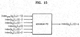
- FIG. 15 shows a preferred embodiment of the configuration of calculation of emission pattern transition using emission pattern bits according to the present invention.
- gray-level change is performed according to Formula (16) using the increment ⁇ of a pixel group number minimizing a PD value within the range of variation of pixel group number from -2 to 2.
- FIG. 14 is a flowchart of a method of eliminating false contour according to an embodiment of the present invention. It is determined whether an input image is a still frame using Formulae (1) through (4) in step 1401. Step 1401 may be omitted according to circumstances. If it is determined that the input image is a still frame, the input image is output without changing its gray level in step 1405. However, if it is determined that the input image is not a still frame, the pixel group number of a pixel of the input image is calculated in step 1402.
- a difference between the calculated pixel group number of the current pixel and a pixel group number corresponding to the gray level of a previous frame pixel that was actually displayed at the same spatial position as the current pixel is calculated in step 1403.
- step 1404 It is determined whether the calculated difference is zero in step 1404. If it is determined that the calculated difference is zero, the gray level of the current pixel is output without changing it in step 1405. Conversely, if it is determined that the calculated difference is non-zero, the gray level of the current pixel is changed in step 1406.
- the calculated pixel group number difference between the current pixel and the previous frame pixel is stored in step 1407. Thereafter, it is determined whether the current pixel is the last one of the input image in step 1408. If it is determined that the current pixel is not the last one, the method progresses to step 1402 to perform the operation on another pixel in the input image.
- the above-described preferred embodiments of the present invention can be realized as programs, which can be executed in a universal digital computer through a computer-readable recording medium.
- the structures of data used in the above-described embodiments of the present invention can be recorded in a computer-readable recording medium using various devices.
- the computer-readable recording medium may be a storage media, such as a magnetic storage medium (for example, a ROM, a floppy disc, or a hard disc), an optical readable medium (for example, a CD-ROM or DVD), or carrier waves (for example, transmitted through the Internet).
- existence/non-existence of motion of a current input pixel is determined using difference information between the current input pixel and a previous frame pixel, without extracting motion information through a complicate procedure.
- the emission pattern of higher weighted subfields are compared between actual PDP driving data regarding to the previous frame pixel and current input data, and the gray level of the current input pixel is changed to have the same emission pattern of weighted subfields as the actual PDP driving data regarding to the previous frame pixel, thereby eliminating false contour.
- emission pattern transition of the higher weighted subfields is regular with an increase in an input gray level, and thus an error due to gray-level change can be reduced. Consequently, the degree of perception of diffused noise due to error diffusion is reduced.
- original input data is output as it is, thereby preventing problems caused by the lack of gray levels.
Landscapes
- Engineering & Computer Science (AREA)
- Physics & Mathematics (AREA)
- Computer Hardware Design (AREA)
- General Physics & Mathematics (AREA)
- Theoretical Computer Science (AREA)
- Power Engineering (AREA)
- Plasma & Fusion (AREA)
- Control Of Indicators Other Than Cathode Ray Tubes (AREA)
- Control Of Gas Discharge Display Tubes (AREA)
- Picture Signal Circuits (AREA)
- Transforming Electric Information Into Light Information (AREA)
Claims (34)
- Appareil pour la réduction de faux contours dans des panneaux d'affichage numériques, l'appareil comprenant :■ un convertisseur de données (131), prévu pour traiter un signal d'image de telle sorte qu'un niveau de gris du signal d'image existe à l'intérieur d'une plage prédéterminée ;■ un diffuseur d'erreur (132), prévu pour diffuser une erreur entre un niveau de gris d'un pixel actuel dans une trame actuelle du signal d'image reçu depuis le convertisseur de données (131) et un niveau de gris du pixel actuel dans la trame actuelle après qu'il ait été soumis à un changement du niveau de gris, vers des pixels adjacents au pixel actuel dans la trame actuelle,■ une première unité de changement de niveau de gris (133), prévue pour recevoir le signal d'image depuis le diffuseur d'erreur (132), pour calculer une différence dans un niveau de gris entre chacun des pixels dans la trame actuelle du signal d'image, que l'on appellera par la suite le pixel de la trame actuelle, et un pixel correspondant au pixel de la trame actuelle dans une trame précédente du signal d'image, que l'on appellera par la suite le pixel de la trame précédente, et pour changer de façon sélective le niveau de gris du pixel de la trame actuelle sur la base de la différence de niveau de gris, de telle sorte qu'une transition dans le tracé d'émission de zones secondaires supérieures pondérées, faisant partie de zones secondaires n'ayant pas toutes le même coefficient de pondération, et qui s'allument en fonction du niveau de gris du pixel de la trame actuelle, entre le pixel de la trame actuelle et le pixel de la trame précédente, soit réduite ; et■ un convertisseur de zone secondaire (134), prévu pour convertir des zones secondaires en fonction du niveau de gris délivré en sortie par l'unité de changement de niveau de gris.
- Appareil selon la revendication 1, dans lequel le convertisseur de zone secondaire (134) représente les niveaux de gris des zones secondaires dans le signal d'image avec des coefficients de pondération entiers D0 à D9 selon un ordre croissant depuis une valeur la plus basse à une valeur la plus haute conformément à une règle prédéterminée selon laquelle les coefficients de pondération D0, D1, D2, D3, D4, D5 et D6 sont prévus selon une progression arithmétique, de telle sorte que D3 = D0 + D1 + D2 + 1, D4 = D3 + d, D5 = D4 + d, et que D6 = D5 + d, et de telle sorte que les coefficients de pondération D7, D8 et D9 satisfont la règle D7 = D5 = D9 = D6 + d, où d est une constante entière positive.
- Appareil selon la revendication 1, dans lequel le convertisseur de zone secondaire (134) représente les niveaux de gris des zones secondaires dans le signal d'image avec des coefficients de pondération entiers D0 à D9 selon un ordre croissant depuis une valeur la plus basse à une valeur la plus haute conformément à une règle prédéterminée selon laquelle les coefficients de pondération les plus élevés D7, D8 et D9 ne permettent pas à une transition de tracé d'émission de se produire avec une augmentation du niveau de gris du signal d'image, et selon laquelle des coefficients de pondération élevés D3, D4, D5 et D6 permettent à un état "off" (de désactivation) d'avoir une distribution régulière avec l'augmentation du niveau de gris du signal d'image.
- Appareil selon la revendication 1, dans lequel le convertisseur de zone secondaire (134) représente les niveaux de gris des zones secondaires dans le signal d'image avec des coefficients de pondération entiers D0 à D9 selon un ordre croissant depuis une valeur la plus basse à une valeur la plus haute conformément à une règle prédéterminée selon laquelle un tracé d'émission change uniquement aux coefficients de pondération D0, D1, D2, D3, D4, D5 et D6 avec un changement dans le niveau de gris du signal d'image.
- Appareil selon la revendication 1, dans lequel la première unité de changement de niveau de gris (133) comprend :■ une section de mémoire de trame (1331), qui reçoit le signal d'image depuis le convertisseur de données (131) et qui enregistre des informations relatives à une trame actuellement entrée, comme des informations de trame précédente pour une trame entrée par la suite ;■ un dispositif de détermination de transition de pixel (1332), qui reçoit des informations de trame actuelle du signal d'image depuis le diffuseur d'erreur (132) et les informations de la trame précédente depuis la section de mémoire de trame (1331), et qui détermine un degré de transition de niveau de gris entre chacun des pixels dans la trame actuelle et un pixel correspondant dans la trame précédente ;■ un dispositif de détermination d'image fixe (1333), qui reçoit le degré de transition de niveau de gris depuis le dispositif de détermination de transition de pixel (1332), et qui détermine si la trame actuelle est, ou non, une image fixe sur la base du degré de transition de niveau de gris et d'un niveau prédéterminé ;■ une section d'enregistrement de numéro de groupe de pixel (1335), qui enregistre des informations relatives à un numéro de groupe de pixel se rapportant à chacun des pixels dans la trame précédente sur la base du niveau de gris du pixel après qu'il ait été soumis au changement de niveau de gris ; et■ une deuxième unité de changement de niveau de gris (1334) qui, lorsque le dispositif de détermination d'image fixe (1333) détermine que la trame actuelle n'est pas une image fixe, change le niveau de gris de la trame actuelle conformément à un procédé prédéterminé en utilisant les informations de trame actuelle délivrées en sortie par le diffuseur d'erreur (132), le degré de transition de niveau de gris délivré en sortie par le dispositif de détermination de transition de pixel (1332), les informations de la trame précédente enregistrées dans la section de mémoire de trame (1331), et les informations relatives à un numéro de groupe de pixel enregistrées dans la section d'enregistrement de numéro de groupe de pixel (1335).
- Appareil selon la revendication 5, dans lequel la deuxième unité de changement de niveau de gris (1334) délivre en sortie un niveau de gris de la trame précédente lorsque le dispositif de détermination d'une image fixe (1333) détermine que la trame actuelle est une image fixe.
- Appareil selon la revendication 5 ou 6, dans lequel le dispositif de détermination de transition de pixel (1332) détermine le degré de transition de niveau de gris entre un pixel particulier dans la trame actuelle, c'est à dire, un pixel de la trame actuelle, et un pixel correspondant dans une trame précédente, en utilisant une moyenne de niveau de gris de tous les pixels inclus dans un bloc carré qui a une taille prédéterminée et qui a le pixel de la trame actuelle en son centre, une moyenne des valeurs absolues des niveaux de gris de tous les pixels qui sont inclus dans le bloc carré à l'exception du pixel de la trame actuelle, une moyenne des valeurs absolues des différences entre les niveaux de gris de tous les pixels qui sont inclus dans le bloc carré et des niveaux de gris respectifs de tous les pixels qui sont inclus dans un bloc carré qui a la taille prédéterminée et qui a le pixel de la trame précédente en son centre, et une valeur absolue d'une différence entre le niveau de gris du pixel de la trame actuelle et le niveau de gris du pixel de la trame précédente.
- Appareil selon l'une quelconque des revendications 5 à 7, dans lequel le dispositif de détermination d'une image fixe (1332) détermine que la trame actuelle est une image fixe lorsqu'un rapport du nombre de pixels qui sont déterminés comme ayant moins de mouvement qu'un nombre prédéterminé dans la trame actuelle du signal d'image reçu depuis le dispositif de détermination d'une image fixe (1332) à un nombre total de pixels dans la trame actuelle, est supérieur à la valeur prédéterminée.
- Appareil selon l'une quelconque des revendications 5 à 8, dans lequel la deuxième unité de changement de niveau de gris (1334) compare le degré de transition de niveau de gris déterminé par le dispositif de détermination de transition de pixel à un niveau prédéterminé, et change le niveau de gris de chacun des pixels dans la trame actuelle sur la base du résultat de la comparaison.
- Appareil selon l'une quelconque des revendications 5 à 8, dans lequel la deuxième unité de changement de niveau de gris (1334) compare le degré de transition de niveau de gris déterminé par le dispositif de détermination de transition de pixel (1332) à un niveau prédéterminé et, lorsque le degré de transition de niveau de gris est inférieur au niveau prédéterminé et lorsqu'un numéro de groupe de pixel d'un pixel dans la trame actuelle, c'est à dire, le pixel de la trame actuelle, est différent d'un numéro de groupe de pixel d'un pixel correspondant dans la trame précédente, c'est à dire, le pixel de la trame précédente, change le numéro de groupe de pixel du pixel de la trame actuelle pour un numéro de groupe de pixel qui se rapproche du numéro de groupe de pixel du pixel de la trame précédente parmi les numéros de groupe de pixel adjacents au numéro de groupe de pixel du pixel de la trame actuelle.
- Appareil selon la revendication 5, dans lequel, lorsque le convertisseur de zone secondaire (134) représente les niveaux de gris de zones secondaires dans le signal d'image avec des coefficients de pondération entiers D0 à D9 selon un ordre croissant depuis une valeur la plus basse à une valeur la plus haute conformément à une règle prédéterminée, la deuxième unité de changement de niveau de gris (1334) change les coefficients de pondération représentant le niveau de gris du pixel de la trame actuelle de telle sorte qu'un tracé d'émission de la trame actuelle soit identique à celui de la trame précédente en ce qui concerne les coefficients de pondération D3, D4 et D5.
- Appareil selon la revendication 5, dans lequel, lorsque le convertisseur de zone secondaire (134) représente les niveaux de gris de zones secondaires dans le signal d'image avec des coefficients de pondération entiers D0 à D9 selon un ordre croissant depuis une valeur la plus basse à une valeur la plus haute conformément à une règle prédéterminée, la deuxième unité de changement de niveau de gris (1334) change les coefficients de pondération représentant le niveau de gris du pixel de la trame actuelle de telle sorte qu'une distribution d'états d'activation au niveau des coefficients de pondération D3, D4, D5 et D6 soit uniforme dans une direction diagonale lorsque les états d'activation des coefficients de pondération D0 à D9 sont prévus selon un ordre croissant des niveaux de gris.
- Appareil selon la revendication 5, dans lequel, lorsque le niveau de gris du signal d'image est divisé en 25 niveaux de gris conformément à une norme prédéterminée et que des numéros de groupe de pixel partant de zéro sont attribués de manière séquentielle aux 25 niveaux de gris, la deuxième unité de changement de niveau de gris (1334) ne change pas les niveaux de gris correspondant aux numéros de groupe de pixel 0 et 1.
- Appareil selon la revendication 13, dans lequel la deuxième unité de changement de niveau de gris (1334) obtient des informations relatives au numéro de groupe de pixel du pixel de la trame précédente après qu'il a été soumis à un changement du niveau de gris en utilisant la formule suivante :

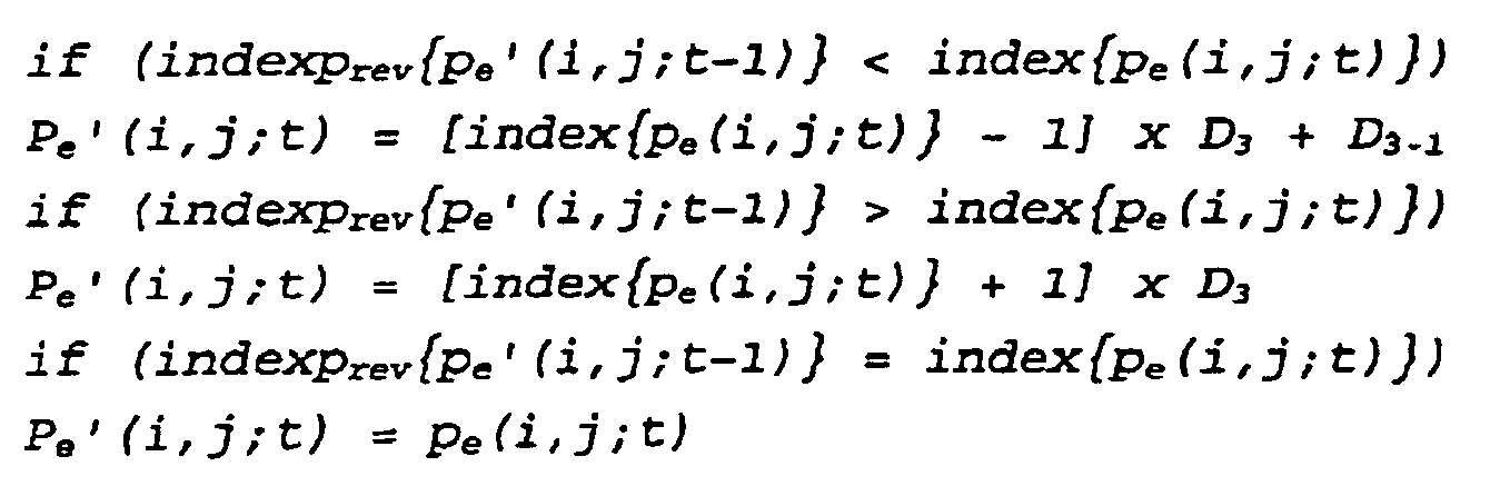
- Appareil selon la revendication 5, dans lequel, lorsque le degré de transition de niveau de gris reçu depuis le dispositif de détermination de transition de pixel (1332) est inférieur au niveau prédéterminé, la deuxième unité de changement de niveau de gris (1334) change le niveau de gris de la trame actuelle en utilisant la formule suivante :
- Appareil selon la revendication 5, dans lequel, lorsque le convertisseur de zone secondaire (134) représente les niveaux de gris de zones secondaires dans le signal d'image avec des coefficients de pondération entiers D0 à D9 selon un ordre croissant depuis une valeur la plus basse à une valeur la plus haute conformément à une règle prédéterminée, la deuxième unité de changement de niveau de gris (1334) change le niveau de gris du pixel de la trame actuelle en utilisant la formule suivante, en utilisant un numéro de groupe de pixel correspondant à un tracé d'émission de zones secondes supérieures pondérées de telle sorte qu'une différence entre le tracé d'émission des coefficients de pondération correspondant au niveau de gris du pixel de la trame précédente après qu'il ait été soumis à un changement du niveau de gris et le tracé d'émission des coefficients de pondération correspondant au niveau de gris du pixel de la trame actuelle soit réduite :

- Procédé pour la réduction de faux contours dans des panneaux d'affichage numériques, le procédé comprenant les étapes consistant à :a. traiter un signal d'image de telle sorte qu'un niveau de gris du signal d'image existe à l'intérieur d'une plage prédéterminée ;b. diffuser une erreur entre un niveau de gris d'un pixel actuel dans une trame actuelle du signal d'image en résultat de l'étape a. et un niveau de gris du pixel actuel dans la trame actuelle après qu'il ait été soumis à un changement du niveau de gris, vers des pixels adjacents au pixel actuel dans la trame actuelle ;c. calculer une différence dans un niveau de gris entre chacun des pixels dans la trame actuelle du signal d'image en résultat de l'étape b., que l'on appellera par la suite le pixel de la trame actuelle, et un pixel correspondant au pixel de la trame actuelle dans une trame précédente du signal d'image en résultat de l'étape b., et changer de façon sélective le niveau de gris du pixel de la trame actuelle sur la base de la différence de niveau de gris de telle sorte que des zones secondaires supérieures pondérées, faisant partie de zones secondaires n'ayant pas toutes le même coefficient de pondération, et qui s'allument en fonction du niveau de gris du pixel de la trame actuelle, se trouvent dans un état d'activation ou de désactivation permanent ; etd. convertir des zones secondaires en fonction d'un niveau de gris en résultat de l'étape c.
- Procédé selon la revendication 17, dans lequel l'étape d. comprend l'étape consistant à représenter les niveaux de gris des zones secondaires dans le signal d'image avec des coefficients de pondération entiers D0 à D9 selon un ordre croissant depuis une valeur la plus basse à une valeur la plus haute conformément à une règle prédéterminée selon laquelle les coefficients de pondération D0, D1, D2, D3, D4, D5 et D6 sont prévus selon une progression arithmétique, de telle sorte que D3 = D0 + D1 + D2 + 1, D4 = D3 + d, D5 = D4 + d, et que D6 = D5 + d, et de telle sorte que les coefficients de pondération D7, D8 et D9 satisfont la règle D7 = D8 = D9 = D6 + d.
- Procédé selon la revendication 17, dans lequel l'étape d. comprend l'étape consistant à représenter les niveaux de gris des zones secondaires dans le signal d'image avec des coefficients de pondération entiers D0 à D9 selon un ordre croissant depuis une valeur la plus basse à une valeur la plus haute conformément à une règle prédéterminée selon laquelle les coefficients de pondération les plus élevés D7, D8 et D9 ne permettent pas à une transition de tracé d'émission de se produire avec une augmentation du niveau de gris du signal d'image, et selon laquelle des coefficients de pondération élevés D3, D4, D5 et D6 permettent à un état "off" (de désactivation) d'avoir une distribution régulière avec l'augmentation du niveau de gris du signal d'image.
- Procédé selon la revendication 17, dans lequel l'étape d. comprend l'étape consistant à représenter les niveaux de gris des zones secondaires dans le signal d'image avec des coefficients de pondération entiers D0 à D9 selon un ordre croissant depuis une valeur la plus basse à une valeur la plus haute conformément à une règle prédéterminée selon laquelle un tracé d'émission change uniquement aux coefficients de pondération D0, D1, D2, D3, D4, D5 et D6 avec un changement dans le niveau de gris du signal d'image.
- Procédé selon la revendication 17, dans lequel l'étape c. comprend les étapes consistant à :c1. enregistrer des informations relatives à une trame actuellement entrée du signal d'image en résultat de l'étape a. comme des informations relatives à un pixel de la trame précédente pour une trame entrée par la suite ;c2. déterminer un degré de transition de niveau de gris entre chacun des pixels dans la trame actuelle et un pixel correspondant dans la trame précédente sur la base des informations relatives à une trame actuellement entrée du signal d'image en résultat de l'étape a. et des informations de la trame précédente en résultat de l'étape c1. ;c3. déterminer si la trame actuelle est, ou non, une image fixe sur la base du degré de transition de niveau de gris et d'un niveau prédéterminé ;c4. enregistrer des informations relatives à un numéro de groupe de pixel se rapportant à chacun des pixels dans la trame précédente sur la base du niveau de gris du pixel après qu'il ait été soumis au changement de niveau de gris ; etc5. lorsque la trame actuelle est déterminée comme n'étant une image fixe, changer le niveau de gris de la trame actuelle conformément à un procédé prédéterminé en utilisant les informations de trame actuelle, le degré de transition de niveau de gris, les informations de la trame précédente, et les informations relatives à un numéro de groupe de pixel.
- Procédé selon la revendication 21, dans lequel l'étape c5. comprend l'étape consistant à délivrer en sortie un niveau de gris de la trame précédente lorsque la trame actuelle est déterminée comme étant une image fixe à l'étape c3.
- Procédé selon la revendication 21, dans lequel l'étape c2. comprend l'étape consistant à déterminer le degré de transition de niveau de gris entre un pixel particulier dans la trame actuelle, c'est à dire, un pixel de la trame actuelle, et un pixel correspondant dans une trame précédente, en utilisant une moyenne de niveau de gris de tous les pixels inclus dans un bloc carré qui a une taille prédéterminée et qui a le pixel de la trame actuelle en son centre, une moyenne des valeurs absolues des niveaux de gris de tous les pixels qui sont inclus dans le bloc carré à l'exception du pixel de la trame actuelle, une moyenne des valeurs absolues des différences entre les niveaux de gris de tous les pixels qui sont inclus dans le bloc carré et des niveaux de gris respectifs de tous les pixels qui sont inclus dans un bloc carré qui a une taille prédéterminée et qui a le pixel de la trame précédente en son centre, et une valeur absolue d'une différence entre le niveau de gris du pixel de la trame actuelle et le niveau de gris du pixel de la trame précédente.
- Procédé selon la revendication 21, dans lequel l'étape c3. comprend l'étape consistant à déterminer la trame actuelle comme étant une image fixe lorsqu'un rapport du nombre de pixels, qui sont déterminés comme ayant moins de mouvement qu'un nombre prédéterminé dans la trame actuelle du signal d'image en résultat de l'étape c2., à un nombre total de pixels dans la trame actuelle, est supérieur à une valeur prédéterminée.
- Procédé selon la revendication 21, dans lequel l'étape c5. comprend les étapes consistant à comparer le degré de transition de niveau de gris en résultat de l'étape c2. à un niveau prédéterminé, et à changer le niveau de gris de chacun des pixels dans la trame actuelle sur la base du résultat de la comparaison.
- Procédé selon la revendication 21, dans lequel l'étape c5. comprend les étapes consistant à comparer le degré de transition de niveau de gris en résultat de l'étape c2. à un niveau prédéterminé et, lorsque le degré de transition de niveau de gris est inférieur au niveau prédéterminé et lorsqu'un numéro de groupe de pixel d'un pixel dans la trame actuelle, c'est à dire, le pixel de la trame actuelle, est différent d'un numéro de groupe de pixel d'un pixel correspondant dans la trame précédente, c'est à dire, le pixel de la trame précédente, à changer le numéro de groupe de pixel du pixel de la trame actuelle pour un numéro de groupe de pixel qui se rapproche du numéro de groupe de pixel du pixel de la trame précédente parmi les numéros de groupe de pixel adjacents au numéro de groupe de pixel du pixel de la trame actuelle.
- Procédé selon la revendication 21, dans lequel, lorsque les niveaux de gris de zones secondaires dans le signal d'image sont représentés avec des coefficients de pondération entiers D0 à D9 selon un ordre croissant depuis une valeur la plus basse à une valeur la plus haute conformément à une règle prédéterminée, l'étape c5. comprend l'étape consistant à changer les coefficients de pondération représentant le niveau de gris du pixel de la trame actuelle de telle sorte qu'un tracé d'émission de la trame actuelle soit identique à celui de la trame précédente en ce qui concerne les coefficients de pondération D3, D4 et D5.
- Procédé selon la revendication 21, dans lequel, lorsque les niveaux de gris de zones secondaires dans le signal d'image sont représentés avec des coefficients de pondération entiers D0 à D9 selon un ordre croissant depuis une valeur la plus basse à une valeur la plus haute conformément à une règle prédéterminée, l'étape c5. comprend l'étape consistant à changer les coefficients de pondération représentant le niveau de gris du pixel de la trame actuelle de telle sorte qu'une distribution d'états d'activation au niveau des coefficients de pondération D3, D4, D5 et D6 soit uniforme dans une direction diagonale lorsque les états d'activation des coefficients de pondération D0 à D9 sont prévus selon un ordre croissant des niveaux de gris.
- Procédé selon la revendication 21, dans lequel, lorsque le niveau de gris du signal d'image est divisé en 25 gris niveaux de gris conformément à une norme prédéterminée et que des numéros de groupe de pixel partant de zéro sont attribués de manière séquentielle aux 25 niveaux de gris, l'étape c5. comprend l'étape consistant à ne pas changer les niveaux de gris correspondant aux numéros de groupe de pixel 0 et 5.
- Procédé selon la revendication 29, dans lequel l'étape c5. comprend l'étape consistant à obtenir des informations relatives au numéro de groupe de pixel du pixel de la trame précédente après qu'il ait été soumis à un changement du niveau de gris en utilisant la formule suivante :

- Procédé selon la revendication 21, dans lequel, lorsque le degré de transition de niveau de gris en résultat de l'étape c2. est inférieur au niveau prédéterminé, l'étape c5. comprend l'étape consistant à changer le niveau de gris de la trame actuelle en utilisant la formule suivante :

- Programme d'ordinateur comprenant des moyens de codage de programme d'ordinateur adaptés pour exécuter l'ensemble des étapes selon l'une quelconque des revendications 17 à 31, lorsque ledit programme est exécuté sur un ordinateur.
- Programme d'ordinateur selon la revendication 32 qui est mis en oeuvre sur un support lisible par un ordinateur.
- Appareil pour commander l'affichage d'un panneau d'affichage numérique, l'appareil comprenant :■ une unité d'entrée de signal d'image (100), qui est prévue pour séparer uniquement un signal d'image analogique d'un signal d'image composite entré ;■ un convertisseur analogique-numérique (110), qui est prévu pour convertir le signal d'image analogique en un signal d'image numérique ;■ une unité de correction gamma (120), qui est prévue pour corriger le signal d'image numérique de manière à ce qu'il soit adapté aux caractéristiques d'un écran d'affichage au plasma ;■ une unité de suppression de faux contours (130), qui est prévue pour convertir des zones secondaires en changeant de façon sélective un niveau de gris du signal d'image numérique corrigé en fonction d'un degré de transition de niveau de gris entre chacun des pixels de la trame actuelle et un pixel correspondant de la trame précédente dans le signal d'image de telle sorte qu'un faux contour soit réduit ; et■ une unité de contrôle d'écran (140), qui est prévue pour afficher le signal d'image de zone secondaire converti reçu depuis l'unité de suppression de faux contours (130) sur l'écran d'affichage au plasma,dans lequel l'unité de suppression de faux contours (130) comprend un appareil selon l'une quelconque des revendications 1 à 16.
Applications Claiming Priority (2)
| Application Number | Priority Date | Filing Date | Title |
|---|---|---|---|
| KR2002061494 | 2002-10-09 | ||
| KR10-2002-0061494A KR100486715B1 (ko) | 2002-10-09 | 2002-10-09 | 펄스수 변조방식 디지털 디스플레이 패널에서 의사 윤곽감소를 위한 방법 및 장치 |
Publications (3)
| Publication Number | Publication Date |
|---|---|
| EP1408683A2 EP1408683A2 (fr) | 2004-04-14 |
| EP1408683A3 EP1408683A3 (fr) | 2004-10-20 |
| EP1408683B1 true EP1408683B1 (fr) | 2006-04-19 |
Family
ID=36314075
Family Applications (1)
| Application Number | Title | Priority Date | Filing Date |
|---|---|---|---|
| EP03255189A Expired - Lifetime EP1408683B1 (fr) | 2002-10-09 | 2003-08-21 | Procédé et appareil pour la réduction de faux contours dans panneaux d'affichages avec modulation du nombre d'impulsions |
Country Status (5)
| Country | Link |
|---|---|
| US (1) | US7265736B2 (fr) |
| EP (1) | EP1408683B1 (fr) |
| JP (1) | JP4101147B2 (fr) |
| KR (1) | KR100486715B1 (fr) |
| DE (1) | DE60304649T2 (fr) |
Families Citing this family (41)
| Publication number | Priority date | Publication date | Assignee | Title |
|---|---|---|---|---|
| US20030063095A1 (en) * | 2000-12-29 | 2003-04-03 | Sun Microsystems, Inc. | Statistic logic for collecting a histogram of pixel exponent values |
| KR100472483B1 (ko) * | 2002-11-29 | 2005-03-10 | 삼성전자주식회사 | 의사 윤곽 제거 방법 및 이에 적합한 장치 |
| US8305301B1 (en) | 2003-02-04 | 2012-11-06 | Imaging Systems Technology | Gamma correction |
| US8289233B1 (en) | 2003-02-04 | 2012-10-16 | Imaging Systems Technology | Error diffusion |
| JP4559041B2 (ja) * | 2003-06-12 | 2010-10-06 | パナソニック株式会社 | 多階調画像表示装置及びその動画偽輪郭低減方法 |
| US7706448B2 (en) * | 2003-07-30 | 2010-04-27 | Microsoft Corporation | Reversible diffusion-based compression |
| JP2005192190A (ja) * | 2003-12-01 | 2005-07-14 | Pioneer Plasma Display Corp | 動画偽輪郭低減方法、動画偽輪郭低減回路、表示装置及びプログラム |
| CN100501813C (zh) * | 2003-12-26 | 2009-06-17 | 松下电器产业株式会社 | 图像信号处理装置以及图像信号处理方法 |
| WO2005079059A1 (fr) * | 2004-02-18 | 2005-08-25 | Matsushita Electric Industrial Co., Ltd. | Méthode de correction d’images et appareil de correction d’image |
| CN100466045C (zh) * | 2004-05-18 | 2009-03-04 | 株式会社半导体能源研究所 | 半导体显示器件及驱动方法 |
| JP5392965B2 (ja) * | 2004-08-03 | 2014-01-22 | 株式会社半導体エネルギー研究所 | 表示装置 |
| WO2006013799A1 (fr) * | 2004-08-03 | 2006-02-09 | Semiconductor Energy Laboratory Co., Ltd. | Dispositif d'affichage et procede d'attaque |
| US7834889B2 (en) * | 2004-08-24 | 2010-11-16 | Kawasaki Microelectronics, Inc. | Data conversion circuit having look-up table and interpolation circuit and method of data conversion |
| KR100577764B1 (ko) * | 2004-09-08 | 2006-05-10 | 엘지전자 주식회사 | 다중 레벨 노이즈를 이용한 에러 확산 패턴 무늬의 개선방법 및 장치 |
| KR100714871B1 (ko) * | 2005-05-30 | 2007-05-04 | 삼성전자주식회사 | 계조 값 보정방법, 보정 회로, 및 이를 구비하는디스플레이 장치 |
| JP4560730B2 (ja) * | 2005-08-22 | 2010-10-13 | 富士ゼロックス株式会社 | 画像処理装置、画像形成装置、画像処理方法及びプログラム |
| KR20070046418A (ko) * | 2005-10-31 | 2007-05-03 | 엘지전자 주식회사 | 플라즈마 디스플레이 장치 |
| KR20070047551A (ko) * | 2005-11-02 | 2007-05-07 | 엘지전자 주식회사 | 플라즈마 디스플레이 장치 |
| US7567717B1 (en) * | 2005-12-12 | 2009-07-28 | American Megatrends, Inc. | Method, system, and computer-readable medium for the adaptive filtering and compression of video data |
| US20070296667A1 (en) * | 2006-06-26 | 2007-12-27 | Chun-Lun Pan | Driving device and driving method of plasma display panel |
| CN100578584C (zh) * | 2006-07-17 | 2010-01-06 | 中华映管股份有限公司 | 等离子显示面板的驱动装置及其驱动方法 |
| JP4350110B2 (ja) * | 2006-08-23 | 2009-10-21 | 日立プラズマディスプレイ株式会社 | 階調表示処理方法及びプラズマディスプレイ装置 |
| US8532375B2 (en) * | 2007-01-19 | 2013-09-10 | Thomson Licensing | Identifying banding in digital images |
| US8248328B1 (en) | 2007-05-10 | 2012-08-21 | Imaging Systems Technology | Plasma-shell PDP with artifact reduction |
| JP5219609B2 (ja) * | 2008-05-01 | 2013-06-26 | キヤノン株式会社 | フレームレート変換装置、方法及びプログラム |
| JP5219608B2 (ja) * | 2008-05-01 | 2013-06-26 | キヤノン株式会社 | フレームレート変換装置、方法及びプログラム |
| CN101990685A (zh) * | 2008-05-14 | 2011-03-23 | 松下电器产业株式会社 | 等离子显示装置及等离子显示面板的驱动方法 |
| US8179401B2 (en) * | 2009-05-21 | 2012-05-15 | Spatial Photonics, Inc. | Reducing image artifacts in a color sequential display system |
| WO2011000202A1 (fr) * | 2009-06-30 | 2011-01-06 | 四川虹欧显示器件有限公司 | Algorithme de juxtaposition de demi-tons |
| US8285069B2 (en) * | 2010-03-30 | 2012-10-09 | Chunghwa Picture Tubes, Ltd. | Image processing device and method thereof |
| CN103137081B (zh) * | 2011-11-22 | 2014-12-10 | 上海天马微电子有限公司 | 一种显示面板栅驱动电路及显示屏 |
| JP5924478B2 (ja) * | 2011-12-27 | 2016-05-25 | セイコーエプソン株式会社 | 画像処理装置、プロジェクターおよび画像処理方法 |
| US9285389B2 (en) * | 2012-04-02 | 2016-03-15 | Semiconductor Components Industries, Llc | Optical accelerometers |
| TWI449013B (zh) * | 2012-05-22 | 2014-08-11 | Au Optronics Corp | 顯示裝置及其操作方法 |
| US9911179B2 (en) | 2014-07-18 | 2018-03-06 | Dolby Laboratories Licensing Corporation | Image decontouring in high dynamic range video processing |
| EP3073477A1 (fr) * | 2015-03-27 | 2016-09-28 | BAE Systems PLC | Affichage numérique |
| EP3271912A1 (fr) * | 2015-03-18 | 2018-01-24 | BAE Systems PLC | Dispositif d'affichage numérique |
| WO2018172151A1 (fr) * | 2017-03-23 | 2018-09-27 | Philips Lighting Holding B.V. | Système et procédé d'éclairage |
| CN111556612B (zh) * | 2020-06-04 | 2022-02-18 | 黄萍 | 一种电源线载波驱动led灯体的压缩灰度控制码协议 |
| KR102911832B1 (ko) * | 2020-07-30 | 2026-01-15 | 삼성디스플레이 주식회사 | 표시 장치 |
| KR20230041113A (ko) * | 2021-09-16 | 2023-03-24 | 삼성디스플레이 주식회사 | 표시장치 |
Family Cites Families (13)
| Publication number | Priority date | Publication date | Assignee | Title |
|---|---|---|---|---|
| US6025818A (en) * | 1994-12-27 | 2000-02-15 | Pioneer Electronic Corporation | Method for correcting pixel data in a self-luminous display panel driving system |
| JP3476107B2 (ja) * | 1994-12-27 | 2003-12-10 | パイオニア株式会社 | 自発光表示パネルの駆動方法 |
| US6052491A (en) * | 1996-01-26 | 2000-04-18 | Texas Instruments Incorporated | Non-monotonic contour diffusion and algorithm |
| JP3719783B2 (ja) * | 1996-07-29 | 2005-11-24 | 富士通株式会社 | 中間調表示方法および表示装置 |
| WO1998044479A1 (fr) * | 1997-03-31 | 1998-10-08 | Matsushita Electric Industrial Co., Ltd. | Procede de visualisation du premier plan d'images et dispositif connexe |
| DE69842070D1 (de) * | 1997-04-02 | 2011-02-03 | Panasonic Corp | Bildanzeigevorrichtung |
| JP3529241B2 (ja) * | 1997-04-26 | 2004-05-24 | パイオニア株式会社 | ディスプレイパネルの中間調表示方法 |
| EP1317137B1 (fr) * | 1997-05-27 | 2006-04-26 | Seiko Epson Corporation | Dispositif de traitement d'image et circuit integré à cet effet |
| US5841413A (en) * | 1997-06-13 | 1998-11-24 | Matsushita Electric Industrial Co., Ltd. | Method and apparatus for moving pixel distortion removal for a plasma display panel using minimum MPD distance code |
| DE69841390D1 (de) * | 1997-07-24 | 2010-01-28 | Panasonic Corp | Bildanzeigevorrichtung und Bildbewertungseinrichtung |
| US6097368A (en) * | 1998-03-31 | 2000-08-01 | Matsushita Electric Industrial Company, Ltd. | Motion pixel distortion reduction for a digital display device using pulse number equalization |
| JP4206530B2 (ja) * | 1998-09-18 | 2009-01-14 | パナソニック株式会社 | 画像表示装置の動画疑似輪郭低減方法 |
| TW508941B (en) * | 2001-04-20 | 2002-11-01 | Chunghwa Picture Tubes Ltd | Error diffusion implementation method applied on plasma display panel |
-
2002
- 2002-10-09 KR KR10-2002-0061494A patent/KR100486715B1/ko not_active Expired - Fee Related
-
2003
- 2003-08-21 EP EP03255189A patent/EP1408683B1/fr not_active Expired - Lifetime
- 2003-08-21 DE DE60304649T patent/DE60304649T2/de not_active Expired - Lifetime
- 2003-08-27 US US10/648,643 patent/US7265736B2/en not_active Expired - Fee Related
- 2003-10-09 JP JP2003350363A patent/JP4101147B2/ja not_active Expired - Fee Related
Also Published As
| Publication number | Publication date |
|---|---|
| US20040070590A1 (en) | 2004-04-15 |
| US7265736B2 (en) | 2007-09-04 |
| JP4101147B2 (ja) | 2008-06-18 |
| EP1408683A2 (fr) | 2004-04-14 |
| JP2004133467A (ja) | 2004-04-30 |
| KR100486715B1 (ko) | 2005-05-03 |
| EP1408683A3 (fr) | 2004-10-20 |
| DE60304649D1 (de) | 2006-05-24 |
| DE60304649T2 (de) | 2007-04-05 |
| KR20040032383A (ko) | 2004-04-17 |
Similar Documents
| Publication | Publication Date | Title |
|---|---|---|
| US7265736B2 (en) | Method and apparatus for reducing false contour in digital display panel using pulse number modulation | |
| EP1532607B1 (fr) | Procede et appareil de traitement d'images video ameliorant la compensation d'effet de faux contour dynamique | |
| KR100464713B1 (ko) | Pdp의 구동 방법 및 장치 | |
| US7081906B2 (en) | Driving method and device for flat panel display | |
| US7420576B2 (en) | Display apparatus and display driving method for effectively eliminating the occurrence of a moving image false contour | |
| US20010028347A1 (en) | Image display apparatus and image evaluation apparatus | |
| EP1881476A2 (fr) | Dispositif de commande d'un panneau d'affichage plasma et procédé de commande associé | |
| US7180480B2 (en) | Method and apparatus for removing false contours | |
| US6812936B2 (en) | Method of and unit for displaying an image in sub-fields | |
| KR100702240B1 (ko) | 디스플레이장치 및 그 제어방법 | |
| US20050248508A1 (en) | Display apparatus | |
| JP3562707B2 (ja) | 画像表示装置 | |
| US7453422B2 (en) | Plasma display panel having an apparatus and method for displaying pictures | |
| US7339555B2 (en) | Method and apparatus for displaying an image on a plasma display panel | |
| KR100403698B1 (ko) | 다계조 화상 표시 방법 및 그 장치 | |
| US20060267871A1 (en) | Moving picture processing method and apparatus thereof | |
| KR100508306B1 (ko) | 플라즈마 디스플레이에서의 시공간적 소수화소 분산기반의 오차 확산 방법 | |
| JP3521591B2 (ja) | ディスプレイ装置の誤差拡散処理装置 | |
| JPH08106279A (ja) | ディスプレイ装置の誤差拡散処理装置 | |
| KR100484540B1 (ko) | 단일 오차확산 적용에 의한 플라즈마 디스플레이패널(pdp)에서의 계조 재현 및 의사윤곽 저감 방법 | |
| JP2820036B2 (ja) | ディスプレイ装置の階調補正回路 | |
| JP2820037B2 (ja) | ディスプレイ装置の誤差拡散回路 | |
| JP2975823B2 (ja) | 疑似階調処理装置 | |
| JP2002268604A (ja) | プラズマディスプレイパネルの階調表示処理装置及び処理方法 | |
| JP3346107B2 (ja) | 誤差拡散処理回路 |
Legal Events
| Date | Code | Title | Description |
|---|---|---|---|
| PUAI | Public reference made under article 153(3) epc to a published international application that has entered the european phase |
Free format text: ORIGINAL CODE: 0009012 |
|
| 17P | Request for examination filed |
Effective date: 20030903 |
|
| AK | Designated contracting states |
Kind code of ref document: A2 Designated state(s): AT BE BG CH CY CZ DE DK EE ES FI FR GB GR HU IE IT LI LU MC NL PT RO SE SI SK TR |
|
| AX | Request for extension of the european patent |
Extension state: AL LT LV MK |
|
| PUAL | Search report despatched |
Free format text: ORIGINAL CODE: 0009013 |
|
| AK | Designated contracting states |
Kind code of ref document: A3 Designated state(s): AT BE BG CH CY CZ DE DK EE ES FI FR GB GR HU IE IT LI LU MC NL PT RO SE SI SK TR |
|
| AX | Request for extension of the european patent |
Extension state: AL LT LV MK |
|
| RIC1 | Information provided on ipc code assigned before grant |
Ipc: 7H 04N 5/21 A Ipc: 7H 04N 5/217 B |
|
| 17Q | First examination report despatched |
Effective date: 20050210 |
|
| AKX | Designation fees paid |
Designated state(s): DE FR GB NL |
|
| GRAP | Despatch of communication of intention to grant a patent |
Free format text: ORIGINAL CODE: EPIDOSNIGR1 |
|
| GRAS | Grant fee paid |
Free format text: ORIGINAL CODE: EPIDOSNIGR3 |
|
| GRAA | (expected) grant |
Free format text: ORIGINAL CODE: 0009210 |
|
| AK | Designated contracting states |
Kind code of ref document: B1 Designated state(s): DE FR GB NL |
|
| REG | Reference to a national code |
Ref country code: GB Ref legal event code: FG4D |
|
| REF | Corresponds to: |
Ref document number: 60304649 Country of ref document: DE Date of ref document: 20060524 Kind code of ref document: P |
|
| ET | Fr: translation filed | ||
| PLBE | No opposition filed within time limit |
Free format text: ORIGINAL CODE: 0009261 |
|
| STAA | Information on the status of an ep patent application or granted ep patent |
Free format text: STATUS: NO OPPOSITION FILED WITHIN TIME LIMIT |
|
| 26N | No opposition filed |
Effective date: 20070122 |
|
| PGFP | Annual fee paid to national office [announced via postgrant information from national office to epo] |
Ref country code: DE Payment date: 20130725 Year of fee payment: 11 Ref country code: NL Payment date: 20130726 Year of fee payment: 11 |
|
| PGFP | Annual fee paid to national office [announced via postgrant information from national office to epo] |
Ref country code: FR Payment date: 20130725 Year of fee payment: 11 Ref country code: GB Payment date: 20130729 Year of fee payment: 11 |
|
| REG | Reference to a national code |
Ref country code: DE Ref legal event code: R119 Ref document number: 60304649 Country of ref document: DE |
|
| REG | Reference to a national code |
Ref country code: NL Ref legal event code: V1 Effective date: 20150301 |
|
| GBPC | Gb: european patent ceased through non-payment of renewal fee |
Effective date: 20140821 |
|
| PG25 | Lapsed in a contracting state [announced via postgrant information from national office to epo] |
Ref country code: NL Free format text: LAPSE BECAUSE OF NON-PAYMENT OF DUE FEES Effective date: 20150301 |
|
| REG | Reference to a national code |
Ref country code: FR Ref legal event code: ST Effective date: 20150430 |
|
| REG | Reference to a national code |
Ref country code: DE Ref legal event code: R119 Ref document number: 60304649 Country of ref document: DE Effective date: 20150303 |
|
| PG25 | Lapsed in a contracting state [announced via postgrant information from national office to epo] |
Ref country code: GB Free format text: LAPSE BECAUSE OF NON-PAYMENT OF DUE FEES Effective date: 20140821 Ref country code: DE Free format text: LAPSE BECAUSE OF NON-PAYMENT OF DUE FEES Effective date: 20150303 |
|
| PG25 | Lapsed in a contracting state [announced via postgrant information from national office to epo] |
Ref country code: FR Free format text: LAPSE BECAUSE OF NON-PAYMENT OF DUE FEES Effective date: 20140901 |