EP1409199B1 - Utilisation d'un dispositif pour l'usinage par abrasion de surfaces d'elements et notamment d'elements ou de pieces optiques - Google Patents
Utilisation d'un dispositif pour l'usinage par abrasion de surfaces d'elements et notamment d'elements ou de pieces optiques Download PDFInfo
- Publication number
- EP1409199B1 EP1409199B1 EP02716837A EP02716837A EP1409199B1 EP 1409199 B1 EP1409199 B1 EP 1409199B1 EP 02716837 A EP02716837 A EP 02716837A EP 02716837 A EP02716837 A EP 02716837A EP 1409199 B1 EP1409199 B1 EP 1409199B1
- Authority
- EP
- European Patent Office
- Prior art keywords
- use according
- outlet
- tool
- inlet
- machining
- Prior art date
- Legal status (The legal status is an assumption and is not a legal conclusion. Google has not performed a legal analysis and makes no representation as to the accuracy of the status listed.)
- Expired - Lifetime
Links
- 238000003754 machining Methods 0.000 title claims description 26
- 230000003287 optical effect Effects 0.000 title claims description 16
- 239000007788 liquid Substances 0.000 claims description 15
- 238000005498 polishing Methods 0.000 claims description 15
- 239000003082 abrasive agent Substances 0.000 claims description 7
- 238000000034 method Methods 0.000 claims description 6
- 238000012545 processing Methods 0.000 description 11
- 239000012530 fluid Substances 0.000 description 9
- 238000004519 manufacturing process Methods 0.000 description 4
- 239000000463 material Substances 0.000 description 3
- 229910000831 Steel Inorganic materials 0.000 description 2
- 238000005266 casting Methods 0.000 description 2
- 238000013461 design Methods 0.000 description 2
- 238000006073 displacement reaction Methods 0.000 description 2
- 238000003825 pressing Methods 0.000 description 2
- 239000010959 steel Substances 0.000 description 2
- 229910010293 ceramic material Inorganic materials 0.000 description 1
- 239000003795 chemical substances by application Substances 0.000 description 1
- 238000007796 conventional method Methods 0.000 description 1
- 238000011161 development Methods 0.000 description 1
- 230000018109 developmental process Effects 0.000 description 1
- 239000011521 glass Substances 0.000 description 1
- 239000002184 metal Substances 0.000 description 1
- 239000005304 optical glass Substances 0.000 description 1
- 238000007517 polishing process Methods 0.000 description 1
- 230000000750 progressive effect Effects 0.000 description 1
- 239000010453 quartz Substances 0.000 description 1
- VYPSYNLAJGMNEJ-UHFFFAOYSA-N silicon dioxide Inorganic materials O=[Si]=O VYPSYNLAJGMNEJ-UHFFFAOYSA-N 0.000 description 1
Images
Classifications
-
- B—PERFORMING OPERATIONS; TRANSPORTING
- B24—GRINDING; POLISHING
- B24B—MACHINES, DEVICES, OR PROCESSES FOR GRINDING OR POLISHING; DRESSING OR CONDITIONING OF ABRADING SURFACES; FEEDING OF GRINDING, POLISHING, OR LAPPING AGENTS
- B24B13/00—Machines or devices designed for grinding or polishing optical surfaces on lenses or surfaces of similar shape on other work; Accessories therefor
-
- B—PERFORMING OPERATIONS; TRANSPORTING
- B24—GRINDING; POLISHING
- B24B—MACHINES, DEVICES, OR PROCESSES FOR GRINDING OR POLISHING; DRESSING OR CONDITIONING OF ABRADING SURFACES; FEEDING OF GRINDING, POLISHING, OR LAPPING AGENTS
- B24B31/00—Machines or devices designed for polishing or abrading surfaces on work by means of tumbling apparatus or other apparatus in which the work and/or the abrasive material is loose; Accessories therefor
- B24B31/10—Machines or devices designed for polishing or abrading surfaces on work by means of tumbling apparatus or other apparatus in which the work and/or the abrasive material is loose; Accessories therefor involving other means for tumbling of work
- B24B31/116—Machines or devices designed for polishing or abrading surfaces on work by means of tumbling apparatus or other apparatus in which the work and/or the abrasive material is loose; Accessories therefor involving other means for tumbling of work using plastically deformable grinding compound, moved relatively to the workpiece under the influence of pressure
-
- B—PERFORMING OPERATIONS; TRANSPORTING
- B24—GRINDING; POLISHING
- B24C—ABRASIVE OR RELATED BLASTING WITH PARTICULATE MATERIAL
- B24C1/00—Methods for use of abrasive blasting for producing particular effects; Use of auxiliary equipment in connection with such methods
- B24C1/08—Methods for use of abrasive blasting for producing particular effects; Use of auxiliary equipment in connection with such methods for polishing surfaces, e.g. smoothing a surface by making use of liquid-borne abrasives
Definitions
- the invention relates to the use of a device for the abrasive machining of surfaces of elements and in particular of optical elements or workpieces according to the preamble of claim 1.
- abrasive machining of surfaces as required, for example, for the production of optical elements such as lenses, prisms, plane-parallel plates, etc., as well as molds for casting or pressing optical elements, a variety of methods and devices are known.
- the surface to be treated with contacting tools such as disc grinders, ball grinders, etc., first a grinding process and optionally a fine grinding and then subjected to a polishing a polishing process.
- Most machining operations, where relatively much material is removed, require at least when producing optical surfaces should be, finally a polishing of the surface.
- the polishing takes place according to the prior art in spherical surfaces over a large area with a polishing plate.
- the invention is based on the object to provide a use of the apparatus for abrasive machining of surfaces and in particular for grinding and / or polishing surfaces of optical elements, which allows rapid processing of the surfaces regardless of the shape of the respective machined surface.
- the apparatus for abrasive machining of surfaces comprises a tool having a fluid inlet and a fluid outlet.
- a supply unit conveys to the fluid inlet a liquid in which abrasive agents are dissolved.
- This fluid flows through the tool to an outlet through which it exits the tool.
- This tool is positioned by a positioning device relative to the surface to be machined such that the outlet from which the liquid emerges, the surface to be machined is located in particular with a small distance. It is crucial that the area of the annular gap formed by the boundary walls of the outlet and by the surface to be machined is smaller than the cross-sectional area of the inlet.
- the liquid in which abrasive agents are dissolved at a much higher pressure than the pressure with which it flows into the inlet, through the annular gap radially to the tool.
- the machining of the surface of the workpiece takes place.
- the surface is processed in the region of the annular gap and thus linearly grinding or polishing.
- the machining time is shortened by orders of magnitude compared with the known methods or devices in which there is a substantially punctiform engagement between the tool and the workpiece.
- the ratio of the pressure with which the liquid flows into the tool, to the pressure with which the liquid exits from the annular gap, is inversely proportional to the ratio of the cross-sectional area of the inlet to the cross-sectional area of the annular gap formed.
- the inlet side is operated with comparatively low pressures: the feed unit conveys the liquid at a pressure of less than 20 bar, preferably less than 5 bar, possibly even only with atmospheric pressure.
- the cross-sectional area of the inlet is at least a factor of five greater than the cross-sectional area of the annular gap formed. It is further preferred if the height of the annular gap formed is less than 3 mm and in particular is about 1 mm.
- the positioning device has a control unit which controls the positioning of the tool in accordance with the surface data of the surface to be produced. It is preferred if the positioning of the tools takes place in such a way that the height of the annular gap remains constant during the displacement along the respective paths.
- the positioning device can, in principle, along any tracks relative to the workpiece, d. H. move to the surface to be machined.
- the web may be a meandering path, with either the tool or the workpiece or both being moved.
- a simultaneous displacement of the tool and the element from which a surface is to be processed take place.
- the tool is moved along tracks which extend through the surface vertex and at the same time the workpiece or the element to be machined by a rotary unit is rotated about an axis, in particular the axis of rotation of the surface to be produced.
- the outlet has a circular cross-section
- the tool has a (circular) -cylindrical outer contour at least in the region of the outlet.
- the cross-sectional area of the inlet is smaller than that of the outlet, that a processing of the surface only linear (or annular) in the region of the annular gap and not in the center of the outlet.
- the size of the tool is adapted to the shape of the surface to be processed:
- the outer diameter of the tool in the region of the outlet may be on the order of half the aperture of the optical element, so that a very fast processing of the surface is achieved with the greatest possible homogeneity of the machining process.
- the outer diameter of the tool is preferably of the order of the smallest radius (smallest main radius of curvature) of the surface; This ensures that the height of the annular gap over the entire annular gap formed is practically constant.
- the device can be used for processing any surfaces of elements or workpieces, which may consist of any materials in principle.
- the device can be used for machining turbine blades made of steel due to the high processing speed.
- the respective elements may in the case of lenses, prisms, plane-parallel plates, etc. -. directly manufactured optical elements - made of quartz, an optical glass or a plastic material; If molds for casting and / or pressing etc. of optical elements are to be produced, the elements can also be made of a metal, such as steel, or a ceramic material.
- the device is used for machining aspherical surfaces.
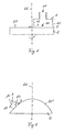
- Fig. 1 shows a device, of which only the tool 1 is shown, in the machining of a flat surface 21 of a workpiece 2, which is a plane-parallel plate without limiting the generality.
- the tool 1 has an inlet 11 and an outlet 12, the cross-sectional area of which is greater than that of the inlet 11.
- An unillustrated supply unit conveys a liquid in which abrasive agents, such as abrasives or polishing agents are dissolved, into the inlet 11 of the tool 1
- the tool 1 is from a positioning unit, not shown positioned relative to the workpiece 2 such that between the boundary walls 13 of the outlet 12 and the surface 21, an annular gap 3 is formed whose cross-sectional area is smaller and preferably substantially smaller than the cross-sectional area of the inlet 11.
- the pressure with which the liquid exits from the annular gap 3 is increased by the ratio of the cross-sectional areas of the inlet 11 and of the annular gap 3.
- the effective for the machining of the workpiece surface 21 pressure is thus much greater than the delivery pressure.
- the positioning device moves the tool 1 parallel to the surface of the workpiece 2, while a rotary unit, also not shown rotates the workpiece 2 about an axis 22, so that the linear engagement along the annular gap 3 is moved over the workpiece 2 that the entire Surface 21 evenly processed, for example, is polished.
- the diameter of the tool 1 is in the order of magnitude of the radius of the workpiece 2.
- Fig. 2 shows a device in the processing of a curved and in particular aspherical surface 21 'of a workpiece 2.
- the same parts are provided with the same reference numerals, so that dispenses with a new idea.
- the diameter of the tool 1 is of the order of magnitude of the smallest radius of the aspheric surface 21 '.
- the positioning unit also not shown, shifts the tool 1 along tracks extending through the apex of the surface 21 '.
- the workpiece 2 is rotated about an axis of rotation 22 extending through the vertex.
Landscapes
- Engineering & Computer Science (AREA)
- Mechanical Engineering (AREA)
- Grinding And Polishing Of Tertiary Curved Surfaces And Surfaces With Complex Shapes (AREA)
Claims (13)
- Utilisation d'un dispositif pour l'usinage par abrasion de surfaces d'éléments, comprenant- un outil (1) qui présente une entrée (11) et une sortie (12),- une unité d'amenée qui amène jusqu'à l'entrée un liquide dans lequel sont dissous des agents abrasifs et qui sort par la sortie, et- un dispositif de positionnement qui amène l'outil (1) sur la surface à usiner (21) et qui le positionne de sorte que la sortie (12) se trouve en face de la surface à usiner (21), la surface de l'interstice annulaire (3) défini par les parois de délimitation (13) de la sortie (12) et la surface à usiner (21 ; 21') étant plus petite que la surface de section de l'entrée (11),caractérisée en ce que l'unité d'amenée amène le liquide avec une pression inférieure à 20 bar, de préférence inférieure à 5 bar.
- Utilisation selon la revendication 1, caractérisée en ce que la surface de section de l'entrée (11) est au moins cinq fois plus grande que la surface de section de l'interstice (3) formé.
- Utilisation selon la revendication 1 ou 2, caractérisée en ce que la hauteur de l'interstice annulaire (3) formé est inférieure à 3 mm et est de préférence d'environ 1 mm.
- Utilisation selon l'une des revendications 1 à 3, caractérisée en ce qu'il est prévu une unité rotative qui tourne l'élément à usiner sur un axe (22).
- Utilisation selon l'une des revendications 1 à 4, caractérisée en ce que la sortie (12) a une section transversale ronde et en ce que l'outil présente au moins dans la zone de la sortie (12) un contour extérieur cylindrique.
- Utilisation selon l'une des revendications 1 à 5, caractérisée en ce que la surface de section de l'entrée (11) est plus petite que celle de la sortie (12).
- Utilisation selon l'une des revendications 1 à 6, caractérisée en ce que pour l'usinage de surfaces planes (21), le diamètre extérieur de l'outil dans la zone de la sortie (12) est de l'ordre de la moitié de l'ouverture de l'élément optique.
- Utilisation selon l'une des revendications 1 à 7, caractérisée en ce que lors de l'usinage de surfaces courbes (21'), le diamètre extérieur de l'outil est de l'ordre du rayon minimal de la surface (21).
- Utilisation selon l'une des revendications 1 à 8, caractérisée en ce que le dispositif de positionnement comprend une unité de commande qui commande le positionnement de l'outil suivant les données de surface de la surface à fabriquer (21 ; 21').
- Utilisation selon l'une des revendications 1 à 9 pour poncer des surfaces optiques (21 ; 21').
- Utilisation selon l'une des revendications 1 à 9 pour polir des surfaces optiques (21 ; 21').
- Utilisation selon l'une des revendications 1 à 9, avec un seul dispositif pour poncer, tout d'abord, puis pour polir une surface optique (21 ; 21').
- Utilisation selon l'une des revendications 1 à 9 pour usiner des surfaces non sphériques (21 ; 21').
Applications Claiming Priority (3)
| Application Number | Priority Date | Filing Date | Title |
|---|---|---|---|
| DE10113599 | 2001-03-20 | ||
| DE10113599A DE10113599A1 (de) | 2001-03-20 | 2001-03-20 | Vorrichtung zur abrasiven Bearbeitung von Flächen von optischen Elementen |
| PCT/EP2002/003120 WO2002074489A1 (fr) | 2001-03-20 | 2002-03-20 | Dispositif pour l'usinage par abrasion de surfaces d'elements et notamment d'elements ou de pieces optiques |
Publications (2)
| Publication Number | Publication Date |
|---|---|
| EP1409199A1 EP1409199A1 (fr) | 2004-04-21 |
| EP1409199B1 true EP1409199B1 (fr) | 2006-11-29 |
Family
ID=7678280
Family Applications (1)
| Application Number | Title | Priority Date | Filing Date |
|---|---|---|---|
| EP02716837A Expired - Lifetime EP1409199B1 (fr) | 2001-03-20 | 2002-03-20 | Utilisation d'un dispositif pour l'usinage par abrasion de surfaces d'elements et notamment d'elements ou de pieces optiques |
Country Status (4)
| Country | Link |
|---|---|
| US (2) | US20060141911A1 (fr) |
| EP (1) | EP1409199B1 (fr) |
| DE (2) | DE10113599A1 (fr) |
| WO (1) | WO2002074489A1 (fr) |
Families Citing this family (17)
| Publication number | Priority date | Publication date | Assignee | Title |
|---|---|---|---|---|
| NL1022293C2 (nl) * | 2002-12-31 | 2004-07-15 | Tno | Inrichting en werkwijze voor het vervaardigen of bewerken van optische elementen en/of optische vormelementen, alsmede dergelijke elementen. |
| DE10314625B3 (de) * | 2003-04-01 | 2004-10-14 | Optotech Optikmaschinen Gmbh | Verfahren und Vorrichtung zum Nacharbeiten von Präzisionsoberflächen |
| MXPA03006434A (es) * | 2003-07-18 | 2005-01-21 | Univ Mexico Nacional Autonoma | Herramienta hidrodinamica de flujo radial para el pulido y esmerilado de superficies opticas. |
| WO2005063441A1 (fr) * | 2003-12-23 | 2005-07-14 | C. Hilzinger-Thum | Procede et dispositif de rectification de surfaces |
| NL1026526C2 (nl) * | 2004-06-30 | 2005-05-31 | Tno | Inrichting en werkwijze voor het vervaardigen of bewerken van optische elementen en/of optische vormelementen, alsmede dergelijke elementen. |
| EP1618992B1 (fr) * | 2004-07-22 | 2008-10-15 | Fisba Optik Ag | Dispositif et procédé de meulage et/ou polissage de surfaces |
| EP1618993B9 (fr) * | 2004-07-22 | 2009-03-18 | Fisba Optik Ag | Procédé pour meuler et/ou polir des surfaces |
| EP1977860B1 (fr) * | 2007-04-04 | 2010-12-15 | Fisba Optik Ag | Dispositif et procédé de fabrication d'éléments optiques |
| GB2471119B (en) * | 2009-06-17 | 2013-11-27 | Nebb Technology As | Rotor or stator blade and method for forming such rotor or stator blade |
| DE102009033206A1 (de) | 2009-07-15 | 2011-01-27 | Brand, Guido | Polierverfahren und Poliervorrichtung zur Korrektur von geometrischen Abweichungsfehlern auf Präzisionsoberflächen |
| CN102284911B (zh) * | 2011-07-22 | 2013-01-02 | 中国科学院长春光学精密机械与物理研究所 | 一种长程抛光稳定间隙装置 |
| CN103128673B (zh) * | 2013-02-05 | 2015-04-29 | 浙江工业大学 | 硬脆材料的约束磨粒流抛光工具头 |
| CN103128672B (zh) * | 2013-02-05 | 2015-02-18 | 浙江工业大学 | 一种约束磨粒流抛光工具头 |
| CN103128671B (zh) * | 2013-02-05 | 2015-04-29 | 浙江工业大学 | 硬脆材料复杂曲面零件的约束磨粒流抛光加工装置 |
| CN105234825A (zh) * | 2015-09-25 | 2016-01-13 | 安庆市凯立金刚石科技有限公司 | 一种用于金刚石膜射流抛光装置 |
| DE102015224933A1 (de) | 2015-12-11 | 2017-06-14 | Siltronic Ag | Monokristalline Halbleiterscheibe und Verfahren zur Herstellung einer Halbleiterscheibe |
| CN116749066A (zh) * | 2023-07-28 | 2023-09-15 | 中国航发动力股份有限公司 | 一种锥孔型零件内型面的抛光装置及其方法 |
Family Cites Families (17)
| Publication number | Priority date | Publication date | Assignee | Title |
|---|---|---|---|---|
| US3769762A (en) * | 1972-03-07 | 1973-11-06 | Altair Scient Inc | Method for controlled lapping of optical surfaces to correct deviations from desired contours |
| US4038786A (en) * | 1974-09-27 | 1977-08-02 | Lockheed Aircraft Corporation | Sandblasting with pellets of material capable of sublimation |
| US4956944A (en) * | 1987-03-19 | 1990-09-18 | Canon Kabushiki Kaisha | Polishing apparatus |
| US5700181A (en) * | 1993-09-24 | 1997-12-23 | Eastman Kodak Company | Abrasive-liquid polishing and compensating nozzle |
| DE4440631C2 (de) * | 1994-11-14 | 1998-07-09 | Trumpf Gmbh & Co | Verfahren und Bearbeitungsmaschine zum Strahlschneiden von Werkstücken mittels wenigstens zweier Schneidstrahlen |
| US5531634A (en) * | 1995-02-03 | 1996-07-02 | Schott; Paul | Method of using an abrasive material for blast cleaning of solid surfaces |
| US5573446A (en) * | 1995-02-16 | 1996-11-12 | Eastman Kodak Company | Abrasive air spray shaping of optical surfaces |
| DE19747838C2 (de) * | 1997-10-19 | 2001-07-12 | Gp Granulate Pneumatic Geraete | Verfahren und Vorrichtung zum trockenen Entfernen von Beschichtungen, Graffiti oder sonstigen oberflächlichen Verunreinigungen |
| NL1007589C1 (nl) * | 1997-11-20 | 1999-05-25 | Tno | Werkwijze en inrichting voor het bewerken van een werkstuk. |
| US6093088A (en) * | 1998-06-30 | 2000-07-25 | Nec Corporation | Surface polishing machine |
| US6244927B1 (en) * | 1998-08-31 | 2001-06-12 | Ingersoll-Rand Company | Multi-functional sensing methods and apparatus therefor |
| US6280302B1 (en) * | 1999-03-24 | 2001-08-28 | Flow International Corporation | Method and apparatus for fluid jet formation |
| JP3990073B2 (ja) * | 1999-06-17 | 2007-10-10 | 株式会社荏原製作所 | 基板洗浄装置及び基板洗浄方法 |
| US6306010B1 (en) * | 1999-10-26 | 2001-10-23 | Industrial Gasket, Inc. | Method of forming a hole in a glass reflector |
| US6425804B1 (en) * | 2000-03-21 | 2002-07-30 | Hewlett-Packard Company | Pressurized delivery system for abrasive particulate material |
| JP3896265B2 (ja) * | 2001-09-11 | 2007-03-22 | オリンパス株式会社 | 位置出し治具及び位置出し治具を用いた吹き付け研磨装置 |
| US6769956B1 (en) * | 2002-02-04 | 2004-08-03 | Oberg Industries | Apparatus and method for rapid, precise positioning of a grit-blasting nozzle |
-
2001
- 2001-03-20 DE DE10113599A patent/DE10113599A1/de not_active Withdrawn
-
2002
- 2002-03-20 US US10/527,468 patent/US20060141911A1/en not_active Abandoned
- 2002-03-20 EP EP02716837A patent/EP1409199B1/fr not_active Expired - Lifetime
- 2002-03-20 DE DE50208850T patent/DE50208850D1/de not_active Expired - Lifetime
- 2002-03-20 WO PCT/EP2002/003120 patent/WO2002074489A1/fr not_active Ceased
-
2007
- 2007-10-31 US US11/931,552 patent/US20080119113A1/en not_active Abandoned
Also Published As
| Publication number | Publication date |
|---|---|
| US20060141911A1 (en) | 2006-06-29 |
| WO2002074489A1 (fr) | 2002-09-26 |
| DE10113599A1 (de) | 2002-10-02 |
| DE50208850D1 (de) | 2007-01-11 |
| EP1409199A1 (fr) | 2004-04-21 |
| US20080119113A1 (en) | 2008-05-22 |
Similar Documents
| Publication | Publication Date | Title |
|---|---|---|
| EP1409199B1 (fr) | Utilisation d'un dispositif pour l'usinage par abrasion de surfaces d'elements et notamment d'elements ou de pieces optiques | |
| DE4242127C2 (de) | Einrichtung zum Schleifen der freien Stirnfläche von Anschlußstücken für optische Fasern | |
| DE19626396B4 (de) | Verfahren und Vorrichtung zur Herstellung und zum Schleifen von Siliziumscheiben | |
| DE19518708C2 (de) | Schleifmaschine zum Erzeugen einer feingeschliffenen, konvexen Stirnfläche an länglichen Werkstücken | |
| DE10144644B4 (de) | Verfahren und Vorrichtung zum Schleifen von zentrischen Lagerstellen von Kurbelwellen | |
| DE19921785B4 (de) | Verfahren zum Schleifen von konvexen Laufflächen und Außendurchmessern an Wellen mit wenigstens einem scheibenförmigen Wellenabschnitt sowie Schleifmaschine zur Durchführung des Verfahrens | |
| WO2000066323A1 (fr) | Degrossissage et finissage a la meule d'un vilebrequin a l'aide d'un seul dispositif de fixation | |
| DE19546863A1 (de) | Verfahren und Vorrichtung zur Endbearbeitung gehärteter Werkstücke | |
| DE69811392T2 (de) | Verfahren und vorrichtung zum bearbeiten eines werkstücks | |
| WO2017211452A1 (fr) | Machine d'usinage de pièces de qualité optique | |
| DE3407615C2 (fr) | ||
| DE4412010C2 (de) | Vorrichtung zum sphärischen Hochglanzschleifen | |
| EP0727280B1 (fr) | Appareil pour polir des lentilles sphériques | |
| DE4022009A1 (de) | Verfahren zur kontaktlosen, maschinellen bearbeitung sphaerischer flaechen | |
| DE202020004003U1 (de) | Werkzeugmaschine zur Laserkonditionierung von Schleifwerkzeugen unabhängig von deren Spezifikation | |
| DE102020128088B3 (de) | Verfahren zum Feinschleifen oder Polieren einer optischen Linse auf einem Werkstückträger | |
| DE19738818B4 (de) | Verfahren und Vorrichtung zur formgeregelten Feinstbearbeitung eines Werkstücks | |
| DE102012216724A1 (de) | Verfahren und Vorrichtung zur Polierbearbeitung von Brillenlinsen und Gießformen für die Brillenlinsenherstellung sowie entsprechendes Verfahren zur Herstellung von Brillenlinsen und Gießformen für die Brillenlinsenherstellung | |
| DE69212109T2 (de) | Bearbeitungsmethode von Aussendurchmesser einer keramischen Hülse | |
| DE19801377A1 (de) | Schleifscheibe mit Umfangsrille | |
| EP1977860B1 (fr) | Dispositif et procédé de fabrication d'éléments optiques | |
| DE102020123003A1 (de) | Verfahren und Vorrichtung zum Schälschleifen einer rotationssymmetrischen Oberfläche eines Werkstücks | |
| WO2008058859A1 (fr) | Procédé d'usinage de finition de dentures coniques de pignons droits, et dispositif pour la mise en œuvre du procédé | |
| DE3113718C2 (de) | Profilschleifmaschine | |
| DD227073A1 (de) | Verfahren zur erzeugung von kugelfoermigen oberflaechen auf koordinatenschleifmaschinen |
Legal Events
| Date | Code | Title | Description |
|---|---|---|---|
| PUAI | Public reference made under article 153(3) epc to a published international application that has entered the european phase |
Free format text: ORIGINAL CODE: 0009012 |
|
| 17P | Request for examination filed |
Effective date: 20031222 |
|
| AK | Designated contracting states |
Kind code of ref document: A1 Designated state(s): AT BE CH CY DE DK ES FI FR GB GR IE IT LI LU MC NL PT SE TR |
|
| AX | Request for extension of the european patent |
Extension state: AL LT LV MK RO SI |
|
| RBV | Designated contracting states (corrected) |
Designated state(s): CH DE FR GB LI NL |
|
| GRAP | Despatch of communication of intention to grant a patent |
Free format text: ORIGINAL CODE: EPIDOSNIGR1 |
|
| RTI1 | Title (correction) |
Free format text: USE OF A DEVICE FOR THE ABRASIVE MACHINING OF SURFACES OF ELEMENTS AND IN PARTICULAR OPTICAL ELEMENTS OR WORKPIECES |
|
| GRAS | Grant fee paid |
Free format text: ORIGINAL CODE: EPIDOSNIGR3 |
|
| GRAA | (expected) grant |
Free format text: ORIGINAL CODE: 0009210 |
|
| AK | Designated contracting states |
Kind code of ref document: B1 Designated state(s): CH DE FR GB LI NL |
|
| REG | Reference to a national code |
Ref country code: GB Ref legal event code: FG4D Free format text: NOT ENGLISH |
|
| REG | Reference to a national code |
Ref country code: CH Ref legal event code: EP |
|
| GBT | Gb: translation of ep patent filed (gb section 77(6)(a)/1977) |
Effective date: 20061220 |
|
| REF | Corresponds to: |
Ref document number: 50208850 Country of ref document: DE Date of ref document: 20070111 Kind code of ref document: P |
|
| REG | Reference to a national code |
Ref country code: CH Ref legal event code: NV Representative=s name: HEPP, WENGER & RYFFEL AG |
|
| ET | Fr: translation filed | ||
| PLBE | No opposition filed within time limit |
Free format text: ORIGINAL CODE: 0009261 |
|
| STAA | Information on the status of an ep patent application or granted ep patent |
Free format text: STATUS: NO OPPOSITION FILED WITHIN TIME LIMIT |
|
| 26N | No opposition filed |
Effective date: 20070830 |
|
| REG | Reference to a national code |
Ref country code: DE Ref legal event code: R082 Ref document number: 50208850 Country of ref document: DE Representative=s name: HAUCK PATENTANWALTSPARTNERSCHAFT MBB, DE |
|
| REG | Reference to a national code |
Ref country code: FR Ref legal event code: PLFP Year of fee payment: 15 |
|
| PGFP | Annual fee paid to national office [announced via postgrant information from national office to epo] |
Ref country code: NL Payment date: 20160310 Year of fee payment: 15 Ref country code: DE Payment date: 20160315 Year of fee payment: 15 |
|
| PGFP | Annual fee paid to national office [announced via postgrant information from national office to epo] |
Ref country code: GB Payment date: 20160316 Year of fee payment: 15 Ref country code: FR Payment date: 20160223 Year of fee payment: 15 |
|
| PGFP | Annual fee paid to national office [announced via postgrant information from national office to epo] |
Ref country code: CH Payment date: 20160531 Year of fee payment: 15 |
|
| REG | Reference to a national code |
Ref country code: DE Ref legal event code: R119 Ref document number: 50208850 Country of ref document: DE |
|
| REG | Reference to a national code |
Ref country code: CH Ref legal event code: PL |
|
| REG | Reference to a national code |
Ref country code: NL Ref legal event code: MM Effective date: 20170401 |
|
| GBPC | Gb: european patent ceased through non-payment of renewal fee |
Effective date: 20170320 |
|
| REG | Reference to a national code |
Ref country code: FR Ref legal event code: ST Effective date: 20171130 |
|
| PG25 | Lapsed in a contracting state [announced via postgrant information from national office to epo] |
Ref country code: NL Free format text: LAPSE BECAUSE OF NON-PAYMENT OF DUE FEES Effective date: 20170401 Ref country code: DE Free format text: LAPSE BECAUSE OF NON-PAYMENT OF DUE FEES Effective date: 20171003 Ref country code: FR Free format text: LAPSE BECAUSE OF NON-PAYMENT OF DUE FEES Effective date: 20170331 |
|
| PG25 | Lapsed in a contracting state [announced via postgrant information from national office to epo] |
Ref country code: LI Free format text: LAPSE BECAUSE OF NON-PAYMENT OF DUE FEES Effective date: 20170331 Ref country code: CH Free format text: LAPSE BECAUSE OF NON-PAYMENT OF DUE FEES Effective date: 20170331 Ref country code: GB Free format text: LAPSE BECAUSE OF NON-PAYMENT OF DUE FEES Effective date: 20170320 |