EP1409363B1 - Energieverstärkungsringe für eine verschlussmembran - Google Patents
Energieverstärkungsringe für eine verschlussmembran Download PDFInfo
- Publication number
- EP1409363B1 EP1409363B1 EP01969431A EP01969431A EP1409363B1 EP 1409363 B1 EP1409363 B1 EP 1409363B1 EP 01969431 A EP01969431 A EP 01969431A EP 01969431 A EP01969431 A EP 01969431A EP 1409363 B1 EP1409363 B1 EP 1409363B1
- Authority
- EP
- European Patent Office
- Prior art keywords
- valve
- ring
- closure
- valve head
- self
- Prior art date
- Legal status (The legal status is an assumption and is not a legal conclusion. Google has not performed a legal analysis and makes no representation as to the accuracy of the status listed.)
- Expired - Lifetime
Links
- 239000012528 membrane Substances 0.000 title 1
- 230000000717 retained effect Effects 0.000 claims description 4
- 238000004806 packaging method and process Methods 0.000 claims description 2
- 239000000463 material Substances 0.000 description 9
- 230000009471 action Effects 0.000 description 3
- 230000008901 benefit Effects 0.000 description 3
- 230000000704 physical effect Effects 0.000 description 2
- 238000007789 sealing Methods 0.000 description 2
- 210000002105 tongue Anatomy 0.000 description 2
- XUIMIQQOPSSXEZ-UHFFFAOYSA-N Silicon Chemical compound [Si] XUIMIQQOPSSXEZ-UHFFFAOYSA-N 0.000 description 1
- 230000001010 compromised effect Effects 0.000 description 1
- 238000002347 injection Methods 0.000 description 1
- 239000007924 injection Substances 0.000 description 1
- 230000003993 interaction Effects 0.000 description 1
- 239000007788 liquid Substances 0.000 description 1
- 230000004048 modification Effects 0.000 description 1
- 238000012986 modification Methods 0.000 description 1
- 230000002093 peripheral effect Effects 0.000 description 1
- 238000005096 rolling process Methods 0.000 description 1
- 229910052710 silicon Inorganic materials 0.000 description 1
- 239000010703 silicon Substances 0.000 description 1
- 239000002210 silicon-based material Substances 0.000 description 1
- 229920002725 thermoplastic elastomer Polymers 0.000 description 1
- 239000012815 thermoplastic material Substances 0.000 description 1
- 230000007704 transition Effects 0.000 description 1
Images
Classifications
-
- B—PERFORMING OPERATIONS; TRANSPORTING
- B65—CONVEYING; PACKING; STORING; HANDLING THIN OR FILAMENTARY MATERIAL
- B65D—CONTAINERS FOR STORAGE OR TRANSPORT OF ARTICLES OR MATERIALS, e.g. BAGS, BARRELS, BOTTLES, BOXES, CANS, CARTONS, CRATES, DRUMS, JARS, TANKS, HOPPERS, FORWARDING CONTAINERS; ACCESSORIES, CLOSURES, OR FITTINGS THEREFOR; PACKAGING ELEMENTS; PACKAGES
- B65D47/00—Closures with filling and discharging, or with discharging, devices
- B65D47/04—Closures with discharging devices other than pumps
- B65D47/20—Closures with discharging devices other than pumps comprising hand-operated members for controlling discharge
- B65D47/2018—Closures with discharging devices other than pumps comprising hand-operated members for controlling discharge comprising a valve or like element which is opened or closed by deformation of the container or closure
- B65D47/2031—Closures with discharging devices other than pumps comprising hand-operated members for controlling discharge comprising a valve or like element which is opened or closed by deformation of the container or closure the element being formed by a slit, narrow opening or constrictable spout, the size of the outlet passage being able to be varied by increasing or decreasing the pressure
Definitions
- the present invention relates to dispersing closures for packaging containers and in particular to closures which include a self-closing valve.
- the invention proposes a means for controlling the opening and closing characteristics of the valve, independently of the design of the self-closing valve itself.
- a dispensing closure having a self-closing valve is disclosed in our PCT patent publication No. W099/10247 .
- the self-closing valves described in this document have a valve head attached by a flexible connecting wall to a mounting ring.
- the valve is mounted in the dispensing closure by engagement of the mounting ring in a valve seat.
- the valve head is essentially cup-shaped, having an upstanding peripheral rim surrounding a concave central region.
- a dispensing aperture is defined by crossed slits in this central region.
- the slits are cut or moulded in the material of the head.
- the crossed slits define resilient tongues which are capable of sealing with one another along the slit edge when the valve is in its "at rest" position.
- Increased product pressure in the container causes the valve head to deform outwardly (away from the interior of the container) and partially invert, causing the slits to gape open to allow product to be dispensed from the container.
- the valve head On release of the product pressure, the valve head reverts back to its concave, essentially cup-shaped configuration and the resilient tongues reseal along the slit edge, allowing air to vent into the container where necessary.
- self-closing valves have conventionally been made from a material having advanced physical properties, in particular flexibility and resilience.
- Liquid silicon has been particularly preferred for this purpose although thermoplastic elastomers have also been considered. It has been necessary to optimise the design of the self-closing valve (particularly the shape and configuration of the valve head and the connecting wall) to ensure satisfactory opening and self-closing characteristics. Thus, generally the performance of the valve has had to be controlled by the material selection and design of the valve.
- WO 00/29296 discloses a closure according, to the preamble of claim 1.
- EP0545678 describes a self-closing valve having a cup-shaped valve head and a mounting ring, joined by a flexible connecting wall, which takes the form of a rolling diaphragm.
- This document discusses the design considerations that need to be addressed to produce a satisfactory self-closing valve. In particular, the need to obtain a sharp "flip" of the valve between its closed, concave configuration and its open, partially inverted configuration. This "flip" ensures that the valve snaps open and closed rather than having a smooth transition between the open and closed positions.
- EP0545678 discusse 5 the importance of valve geometry and material selection when trying to obtain a satisfactory "flip” or snap action.
- this document describes how the geometry of the valve disclosed, provides torque assist to the "flip” action of the valve head.
- the design of the valve head, connector sleeve and connection between the two is designed to increase the outwardly directed torque applied to the valve head to "flip" it between its fully closed and fully open positions.
- valve housing is usually injection moulded from a thermoplastic material and is therefore relatively straightforward to modify.
- the present invention provides a closure according to claim 1.
- the "flip" of the valve head can be affected by supporting the periphery of the valve head or a portion of the flexible connecting wall, as the valve head partially inverts.
- the "flip" of the valve head can be controlled by constraining the radial expansion of the valve head as the dispensing aperture opens. This can most easily be achieved by providing an energising ring surrounding the valve head, which either acts directly on the valve head or on the connecting wall between the valve head and the mounting ring, such that it restricts the radial expansion of the valve head as it partially inverts, producing a more definite "flip" as discussed above.
- valve head or connecting wall and the energising ring also acts to energise the head as the dispensing aperture opens, generating a spring bias to return the valve head to its concave position, thereby snapping the dispensing aperture to its closed position, once the internal pressure of the product in the container is released. This ensures that the self-closing valve has the positive shut off preferred by consumers.
- An advantage of the energising ring is that it can be moulded as part of the closure or valve housing and can be easily modified independently of the self-closing valve. This allows the valve performance to be optimised by adjusting the design and position of the energising ring rather than modifying the design of the self-closing valve. Thus, the cost of developing and optimising the design of the closure is greatly reduced.
- Another advantage of the invention is that it allows a single design of self-closing valve to be used for a number of different applications having different requirements for valve performance.
- the valve performance for each application can be optimised by varying the position and design of the energising ring.
- the energising ring may be used to bias the valve head, to control the threshold pressure at which the dispensing aperture opens, the pressure at which the valve self-closes and thereby control the dose of product dispensed from the container.
- the energising ring is spaced from the valve head or connecting wall by a clearance distance, which is limited by the need to ensure that the valve makes contact with the energising ring before the dispensing aperture snaps open.
- This arrangement ensures that the axial movement of the valve head is unhindered but the contact between the valve and the energising ring as the valve head expands radially, provides torque assist to partially invert the valve head at the end of its axial movement.
- the energising ring is provided as an integral part of the closure body.
- the mounting ring of the self-closing valve is received in a valve seat defined in the valve housing and the valve is retained therein by a retaining ring or clip.
- the retaining ring is preferably adapted to define the energising ring.
- the energising ring may be provided as a separate component, which engages in a recess in the valve housing. This arrangement has the advantage that the same design of closure and self-closing valve may be used for a number of different applications, with only the design of the energising ring having to be adapted for each application.
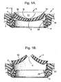
- FIGS 1A and 1B show a dispensing closure 1 having a self-closing valve 3, which is retained in the closure body 2 by means of an upturned flange 26 on the closure body, which forces the mounting ring 31 of the valve against a sealing surface 21 on the closure body 2.
- the self-closing valve 3 comprises a generally concave, cup-shaped valve head 32, connected to a mounting ring 31 by a flexible connecting wall 33.
- the valve head 32 is connected to the flexible connecting wall 33 via a hinge portion.
- the flexible connecting wall 33 is designed for minimum axial movement.
- the valve head 32 moves axially by a small amount by stretching of the connecting wall 33 but there is no folded structure, which unfolds to allow significant axial movement.
- the energising ring 5 is defined by a portion of the closure body 2. Referring to figure 1A , the energising ring 5 is arranged so that it does not contact the connecting wall 33, when the valve 3 is in its "at rest” position. Rather, the energising ring 5 is spaced from the connecting wall 33 by a clearance distance 51, which is selected such that the energising ring 5 does not restrict axial movement of the valve head 32 but does make contact with the connecting wall 33 as the valve head 32 and connecting wall 33 expand radially outwards, restricting the movement thereof and providing the torque assist to "flip" the valve head to its partially inverted, open position.
- the energising ring 5 shown in Fig. 1A is arranged to contact the connecting wall 33, below the hinge portion .
- valve head 32 rises axially and expands radially, until it makes contact with the energising ring 5, which supports the valve head 32 and restricts any further radial expansion. Stresses build up in the connecting wall 33 as it is forced against the energising ring 5. These stresses provide the torque assist required to "flip" the valve head 32 to its partially inverted configuration, there by opening the dispensing aperture 6 (as shown in figure 1B ). The stresses built up in the connecting wall 33, also energise the valve 3 and provide a spring bias to snap the valve head 32 back to its concave, closed position, once the internal pressure in the container is relieved.
- the position and engagement of the energising ring relative the self-closing valve may be varied to produce different opening/closing characteristics for the valve.
- the energising ring may be applied to many other self-closing valve configurations than those shown in figures 1A and 1B .
Landscapes
- Engineering & Computer Science (AREA)
- Mechanical Engineering (AREA)
- Containers And Packaging Bodies Having A Special Means To Remove Contents (AREA)
- Closures For Containers (AREA)
- Pharmaceuticals Containing Other Organic And Inorganic Compounds (AREA)
- Materials For Medical Uses (AREA)
Claims (6)
- Verschluss (1) für einen Verpackungsbehälter, der ein selbstschließendes Ventil (3) mit einem flexiblen, im Wesentlichen schalenförmigen Ventilkopf (32) mit einer darin definierten Ausgabeöffnung (6) aufweist, wobei der Ventilkopf (32) angepasst ist, um sich als Reaktion auf einen erhöhten Druck des Produkts im Behälter abzuflachen und teilweise umzukehren, um die Ausgabeöffnung (6) zu öffnen, wobei der Ventilkopf (32) durch ein Gelenk mit einem Befestigungsring (31) über eine flexible Verbindungswand (33) verbunden ist und von einem Energieverstärkungsring umgeben ist, der die radiale Ausdehnung des Ventilkopfs (32) einschränkt,
dadurch gekennzeichnet, dass
die Verbindungswand (33) zwischen dem Gelenkabschnitt und dem Befestigungsring (31) axial verläuft,
und dadurch dass,
der Energieverstärkungsring (5) so angeordnet ist, dass er mit der Verbindungswand (33) unterhalb des Gelenks in Kontakt steht, um die radiale Ausdehnung der Verbindungswand (33) einzuschränken, wodurch er eine Biegung davon beim Abflachen und dem teilweisen Umkehren des Ventilkopfes (32) verursacht,
und dadurch dass,
der Energieverstärkungsring (5) von dem selbstschließenden Ventil durch einen Sicherheitsabstand (51) beabstandet ist, wenn er in der Ruheposition ist, und der Sicherheitsabstand darauf beschränkt ist, den Kontakt zwischen der Verbindungswand (33) unter dem Gelenk und dem Energieverstärkungsring (5) sicherzustellen, wenn sich der Ventilkopf (32) abflacht und teilweise umkehrt. - Verschluss gemäß Anspruch 1, dadurch gekennzeichnet, dass der Energieverstärkungsring (5) einen vollständigen Ring aufweist.
- Verschluss gemäß Anspruch 1, dadurch gekennzeichnet, das der Energieverstärkungsring (5) einen segmentierten Ring aufweist.
- Verschluss gemäß einem der vorhergehenden Ansprüche, dadurch gekennzeichnet, dass der Verschluss einen Körper (2) aufweist, der den Energieverstärkungsring (5) definiert.
- Verschluss gemäß einem der Ansprüche 1 bis 3,
dadurch gekennzeichnet, dass
das selbstschließende Ventil (3) in dem Verschluss (1) durch einen Halteclip (4) gehalten wird und der Halteclip (4) den Energieverstärkungsring (5) definiert. - Verschluss gemäß einem der Ansprüche 1 bis 3,
dadurch gekennzeichnet, dass
der Verschluss (1) eine darin definierte Aussparung besitzt und der Energieverstärkungsring (5) als eigene Komponente ausgebildet ist, die in der Aussparung des Verschlusses (1) gehalten wird.
Priority Applications (1)
| Application Number | Priority Date | Filing Date | Title |
|---|---|---|---|
| EP01969431A EP1409363B1 (de) | 2000-07-24 | 2001-07-19 | Energieverstärkungsringe für eine verschlussmembran |
Applications Claiming Priority (4)
| Application Number | Priority Date | Filing Date | Title |
|---|---|---|---|
| EP00306281 | 2000-07-24 | ||
| EP00306281 | 2000-07-24 | ||
| EP01969431A EP1409363B1 (de) | 2000-07-24 | 2001-07-19 | Energieverstärkungsringe für eine verschlussmembran |
| PCT/EP2001/008338 WO2002008080A1 (en) | 2000-07-24 | 2001-07-19 | Energising ring for a closure membrane |
Publications (2)
| Publication Number | Publication Date |
|---|---|
| EP1409363A1 EP1409363A1 (de) | 2004-04-21 |
| EP1409363B1 true EP1409363B1 (de) | 2011-11-30 |
Family
ID=8173142
Family Applications (1)
| Application Number | Title | Priority Date | Filing Date |
|---|---|---|---|
| EP01969431A Expired - Lifetime EP1409363B1 (de) | 2000-07-24 | 2001-07-19 | Energieverstärkungsringe für eine verschlussmembran |
Country Status (6)
| Country | Link |
|---|---|
| US (1) | US6971558B2 (de) |
| EP (1) | EP1409363B1 (de) |
| AT (1) | ATE535462T1 (de) |
| AU (1) | AU2001289693A1 (de) |
| ES (1) | ES2376730T3 (de) |
| WO (1) | WO2002008080A1 (de) |
Families Citing this family (27)
| Publication number | Priority date | Publication date | Assignee | Title |
|---|---|---|---|---|
| GB0117928D0 (en) * | 2001-07-23 | 2001-09-12 | Mcgill Tech Ltd | Container with outlet |
| USD495604S1 (en) | 2002-09-26 | 2004-09-07 | Johnson & Johnson Consumer Companies, Inc. | Bottle |
| USD497108S1 (en) | 2002-09-26 | 2004-10-12 | Douglas M. Lund | Bottle |
| ITMI20030713A1 (it) * | 2003-04-09 | 2004-10-10 | Capsol Berry Plastics S P A | Valvola elasticamente deformabile a chiusura automatica |
| US7503469B2 (en) * | 2005-03-09 | 2009-03-17 | Rexam Closure Systems Inc. | Integrally molded dispensing valve and method of manufacture |
| DE102005061491A1 (de) * | 2005-12-22 | 2007-07-05 | Braun Gmbh | Zahnbürste |
| DE102006017957B3 (de) * | 2006-04-13 | 2007-05-16 | Kunststofftechnik Waidhofen An | Selbstschließendes Ventil |
| DE102006021564B3 (de) * | 2006-05-08 | 2007-03-29 | Ccc Udo Suffa Gmbh | Selbstschließendes Ventil mit Ventildeckel |
| DE602007004566D1 (de) * | 2007-02-14 | 2010-03-18 | Avesto Tech Bv | Abgabeventil und damit ausgestatteter Behälter zum Aufnehmen einer Flüssigkeit |
| US8397956B2 (en) * | 2007-03-27 | 2013-03-19 | Aptargroup, Inc. | Dispensing valve with improved dispensing |
| US20090092436A1 (en) * | 2007-10-04 | 2009-04-09 | John Mercier | Anti-spill dauber wiper for a glue container |
| US8678249B2 (en) * | 2008-02-21 | 2014-03-25 | Aptargroup, Inc. | Valve mounting assembly with slit misalignment prevention feature |
| CA2741643C (en) | 2008-10-22 | 2016-01-12 | Scholle Corporation | Self sealing bag in box cap assembly |
| US8316890B2 (en) * | 2008-11-11 | 2012-11-27 | Aptargroup, Inc. | Port closure system with hydraulic hammer resistance |
| US8397958B2 (en) * | 2010-08-05 | 2013-03-19 | Ds Smith Plastics Limited | Closure valve assembly for a container |
| US20120114800A1 (en) * | 2010-11-10 | 2012-05-10 | Ecosentials, Llc | Drink Enhancer System |
| WO2012134498A1 (en) * | 2011-04-01 | 2012-10-04 | Aptargroup, Inc. | Dispensing assembly |
| MX339132B (es) * | 2011-05-04 | 2016-05-13 | Aptargroup Inc | Sistema de obturacion de orificios para usar con una herramienta de sondeo/llenado/vaciado. |
| US8757442B2 (en) | 2012-01-10 | 2014-06-24 | Holdenart, Inc. | Reversible spout for bottles |
| USD728378S1 (en) | 2013-03-15 | 2015-05-05 | Tc Heartland Llc | Container |
| US10518943B2 (en) | 2013-03-15 | 2019-12-31 | Tc Heartland Llc | Container with valve |
| GB201310452D0 (en) | 2013-06-12 | 2013-07-24 | Blagdon Actuation Res Ltd | Fluid Manifolds |
| NL2014225B1 (en) * | 2015-02-03 | 2016-10-12 | Plasticum Netherlands B V | Dispensing closure with self-closing valve. |
| JP2017030846A (ja) * | 2015-08-06 | 2017-02-09 | 株式会社三谷バルブ | カップゴム使用のバックサクション機構、このバックサクション機構を備えた二重容器、およびこの二重容器を備えたスクイーズ操作態様のポンプ式製品 |
| US10836541B2 (en) * | 2017-11-27 | 2020-11-17 | Gateway Plastics, Inc. | Valve for a dispensing container |
| NL2022396B1 (en) | 2019-01-14 | 2020-08-14 | Weener Plastics Group B V | Valve carrier ring for self-closing dispensing valve |
| NL2022764B1 (en) * | 2019-03-19 | 2020-09-28 | Weener Plastics Group B V | Self-closing dispensing valve made of a plastomer or a thermoplastic elastomer |
Family Cites Families (9)
| Publication number | Priority date | Publication date | Assignee | Title |
|---|---|---|---|---|
| DE3531783A1 (de) | 1985-09-06 | 1987-03-19 | Helmut Budjin | Verschluss fuer verformbare tuben |
| US5213236A (en) | 1991-12-06 | 1993-05-25 | Liquid Molding Systems, Inc. | Dispensing valve for packaging |
| US5842618A (en) * | 1995-03-30 | 1998-12-01 | Colgate-Palmolive Company | Dispensing closure with controlled valve actuation |
| CN1079355C (zh) | 1995-09-05 | 2002-02-20 | 策拉塑料有限公司 | 自动闭合的密封装置 |
| DE19613130A1 (de) | 1995-09-05 | 1997-03-06 | Design Udo Suffa Gmbh S | Selbstschließender Verschluß und Verschlußmembran |
| DE19612561A1 (de) | 1996-02-15 | 1997-09-04 | Weener Plastik Gmbh Co Kg | Verschluß |
| JP3523021B2 (ja) * | 1997-06-20 | 2004-04-26 | 株式会社吉野工業所 | 容 器 |
| GB9717595D0 (en) | 1997-08-21 | 1997-10-22 | Metal Box Plc | Valves for packaging containers |
| GB9825121D0 (en) | 1998-11-17 | 1999-01-13 | Crown Cork & Seal Tech Corp | Dispensing closures |
-
2001
- 2001-07-19 US US10/333,840 patent/US6971558B2/en not_active Expired - Fee Related
- 2001-07-19 ES ES01969431T patent/ES2376730T3/es not_active Expired - Lifetime
- 2001-07-19 AU AU2001289693A patent/AU2001289693A1/en not_active Abandoned
- 2001-07-19 AT AT01969431T patent/ATE535462T1/de active
- 2001-07-19 EP EP01969431A patent/EP1409363B1/de not_active Expired - Lifetime
- 2001-07-19 WO PCT/EP2001/008338 patent/WO2002008080A1/en not_active Ceased
Also Published As
| Publication number | Publication date |
|---|---|
| AU2001289693A1 (en) | 2002-02-05 |
| ATE535462T1 (de) | 2011-12-15 |
| WO2002008080A1 (en) | 2002-01-31 |
| US20040040987A1 (en) | 2004-03-04 |
| US6971558B2 (en) | 2005-12-06 |
| EP1409363A1 (de) | 2004-04-21 |
| ES2376730T3 (es) | 2012-03-16 |
Similar Documents
| Publication | Publication Date | Title |
|---|---|---|
| EP1409363B1 (de) | Energieverstärkungsringe für eine verschlussmembran | |
| AU739728B2 (en) | Valves for packaging containers | |
| US5409144A (en) | Dispensing valve for packaging | |
| EP2755899B1 (de) | Abgabeventil | |
| US6367668B1 (en) | Self-closing closure and closure membrane relating to same | |
| EP1426303B1 (de) | Ventil für eine Flüssigkeitsspenderpackung | |
| CN107072416B (zh) | 阀组件 | |
| WO2003021139B1 (en) | Pressure-activated flexible valve | |
| MX2007006941A (es) | Elemento de control de flujo y estructura surtidora que lo incorpora. | |
| CN107873013B (zh) | 分配封闭件以及分配器 | |
| RU2742443C1 (ru) | Клапан | |
| US20060037975A1 (en) | Self-closing valve | |
| JPH0230942B2 (de) | ||
| EP1652813B1 (de) | Zapfhahn zum Ausschenken von Flüssigkeiten aus Behältern | |
| AU2007247210A1 (en) | Self-locking valve with valve cap | |
| CA2311357A1 (en) | Self-closing valve arrangement for the dispensing opening of a container | |
| US6575190B1 (en) | Non-return valve for fuel tank | |
| US6336574B1 (en) | Automatic closure for a container | |
| WO2015149160A1 (en) | Valve closures | |
| CA3175893A1 (en) | Valve | |
| JP2006206056A (ja) | 位置決め容器 | |
| MXPA01007293A (es) | Ensamble para asegurar un dispensador. | |
| US20250263210A1 (en) | Dispensing valve | |
| KR102733626B1 (ko) | 내용물의 배출 및 밀폐기능이 우수한 용기 캡 | |
| JP7785432B2 (ja) | 開封刃付き容器 |
Legal Events
| Date | Code | Title | Description |
|---|---|---|---|
| PUAI | Public reference made under article 153(3) epc to a published international application that has entered the european phase |
Free format text: ORIGINAL CODE: 0009012 |
|
| 17P | Request for examination filed |
Effective date: 20030116 |
|
| AK | Designated contracting states |
Kind code of ref document: A1 Designated state(s): AT BE CH CY DE DK ES FI FR GB GR IE IT LI LU MC NL PT SE TR |
|
| RAP1 | Party data changed (applicant data changed or rights of an application transferred) |
Owner name: CROWN PACKAGING TECHNOLOGY, INC |
|
| R17P | Request for examination filed (corrected) |
Effective date: 20030116 |
|
| 17Q | First examination report despatched |
Effective date: 20060620 |
|
| RAP1 | Party data changed (applicant data changed or rights of an application transferred) |
Owner name: CROWN OBRIST GMBH |
|
| RAP1 | Party data changed (applicant data changed or rights of an application transferred) |
Owner name: OBRIST CLOSURES SWITZERLAND GMBH |
|
| GRAP | Despatch of communication of intention to grant a patent |
Free format text: ORIGINAL CODE: EPIDOSNIGR1 |
|
| GRAJ | Information related to disapproval of communication of intention to grant by the applicant or resumption of examination proceedings by the epo deleted |
Free format text: ORIGINAL CODE: EPIDOSDIGR1 |
|
| GRAP | Despatch of communication of intention to grant a patent |
Free format text: ORIGINAL CODE: EPIDOSNIGR1 |
|
| GRAS | Grant fee paid |
Free format text: ORIGINAL CODE: EPIDOSNIGR3 |
|
| GRAA | (expected) grant |
Free format text: ORIGINAL CODE: 0009210 |
|
| AK | Designated contracting states |
Kind code of ref document: B1 Designated state(s): AT BE CH CY DE DK ES FI FR GB GR IE IT LI LU MC NL PT SE TR |
|
| REG | Reference to a national code |
Ref country code: GB Ref legal event code: FG4D Ref country code: CH Ref legal event code: EP |
|
| REG | Reference to a national code |
Ref country code: IE Ref legal event code: FG4D |
|
| REG | Reference to a national code |
Ref country code: DE Ref legal event code: R096 Ref document number: 60145736 Country of ref document: DE Effective date: 20120119 |
|
| REG | Reference to a national code |
Ref country code: CH Ref legal event code: NV Representative=s name: KIRKER & CIE S.A. |
|
| REG | Reference to a national code |
Ref country code: NL Ref legal event code: T3 |
|
| REG | Reference to a national code |
Ref country code: ES Ref legal event code: FG2A Ref document number: 2376730 Country of ref document: ES Kind code of ref document: T3 Effective date: 20120316 |
|
| PG25 | Lapsed in a contracting state [announced via postgrant information from national office to epo] |
Ref country code: SE Free format text: LAPSE BECAUSE OF FAILURE TO SUBMIT A TRANSLATION OF THE DESCRIPTION OR TO PAY THE FEE WITHIN THE PRESCRIBED TIME-LIMIT Effective date: 20111130 Ref country code: PT Free format text: LAPSE BECAUSE OF FAILURE TO SUBMIT A TRANSLATION OF THE DESCRIPTION OR TO PAY THE FEE WITHIN THE PRESCRIBED TIME-LIMIT Effective date: 20120330 Ref country code: GR Free format text: LAPSE BECAUSE OF FAILURE TO SUBMIT A TRANSLATION OF THE DESCRIPTION OR TO PAY THE FEE WITHIN THE PRESCRIBED TIME-LIMIT Effective date: 20120301 |
|
| PG25 | Lapsed in a contracting state [announced via postgrant information from national office to epo] |
Ref country code: CY Free format text: LAPSE BECAUSE OF FAILURE TO SUBMIT A TRANSLATION OF THE DESCRIPTION OR TO PAY THE FEE WITHIN THE PRESCRIBED TIME-LIMIT Effective date: 20111130 |
|
| PG25 | Lapsed in a contracting state [announced via postgrant information from national office to epo] |
Ref country code: DK Free format text: LAPSE BECAUSE OF FAILURE TO SUBMIT A TRANSLATION OF THE DESCRIPTION OR TO PAY THE FEE WITHIN THE PRESCRIBED TIME-LIMIT Effective date: 20111130 |
|
| REG | Reference to a national code |
Ref country code: AT Ref legal event code: MK05 Ref document number: 535462 Country of ref document: AT Kind code of ref document: T Effective date: 20111130 |
|
| PLBE | No opposition filed within time limit |
Free format text: ORIGINAL CODE: 0009261 |
|
| STAA | Information on the status of an ep patent application or granted ep patent |
Free format text: STATUS: NO OPPOSITION FILED WITHIN TIME LIMIT |
|
| 26N | No opposition filed |
Effective date: 20120831 |
|
| REG | Reference to a national code |
Ref country code: DE Ref legal event code: R097 Ref document number: 60145736 Country of ref document: DE Effective date: 20120831 |
|
| PG25 | Lapsed in a contracting state [announced via postgrant information from national office to epo] |
Ref country code: AT Free format text: LAPSE BECAUSE OF FAILURE TO SUBMIT A TRANSLATION OF THE DESCRIPTION OR TO PAY THE FEE WITHIN THE PRESCRIBED TIME-LIMIT Effective date: 20111130 |
|
| PG25 | Lapsed in a contracting state [announced via postgrant information from national office to epo] |
Ref country code: MC Free format text: LAPSE BECAUSE OF NON-PAYMENT OF DUE FEES Effective date: 20120731 |
|
| REG | Reference to a national code |
Ref country code: IE Ref legal event code: MM4A |
|
| PG25 | Lapsed in a contracting state [announced via postgrant information from national office to epo] |
Ref country code: FI Free format text: LAPSE BECAUSE OF FAILURE TO SUBMIT A TRANSLATION OF THE DESCRIPTION OR TO PAY THE FEE WITHIN THE PRESCRIBED TIME-LIMIT Effective date: 20111130 |
|
| PG25 | Lapsed in a contracting state [announced via postgrant information from national office to epo] |
Ref country code: IE Free format text: LAPSE BECAUSE OF NON-PAYMENT OF DUE FEES Effective date: 20120719 |
|
| PGFP | Annual fee paid to national office [announced via postgrant information from national office to epo] |
Ref country code: LU Payment date: 20130722 Year of fee payment: 13 |
|
| PG25 | Lapsed in a contracting state [announced via postgrant information from national office to epo] |
Ref country code: TR Free format text: LAPSE BECAUSE OF FAILURE TO SUBMIT A TRANSLATION OF THE DESCRIPTION OR TO PAY THE FEE WITHIN THE PRESCRIBED TIME-LIMIT Effective date: 20111130 |
|
| PGFP | Annual fee paid to national office [announced via postgrant information from national office to epo] |
Ref country code: CH Payment date: 20140721 Year of fee payment: 14 Ref country code: NL Payment date: 20140721 Year of fee payment: 14 Ref country code: DE Payment date: 20140721 Year of fee payment: 14 |
|
| PGFP | Annual fee paid to national office [announced via postgrant information from national office to epo] |
Ref country code: GB Payment date: 20140721 Year of fee payment: 14 Ref country code: FR Payment date: 20140721 Year of fee payment: 14 Ref country code: ES Payment date: 20140728 Year of fee payment: 14 |
|
| PGFP | Annual fee paid to national office [announced via postgrant information from national office to epo] |
Ref country code: IT Payment date: 20140728 Year of fee payment: 14 |
|
| PGFP | Annual fee paid to national office [announced via postgrant information from national office to epo] |
Ref country code: BE Payment date: 20140722 Year of fee payment: 14 |
|
| PG25 | Lapsed in a contracting state [announced via postgrant information from national office to epo] |
Ref country code: LU Free format text: LAPSE BECAUSE OF NON-PAYMENT OF DUE FEES Effective date: 20140719 |
|
| REG | Reference to a national code |
Ref country code: DE Ref legal event code: R119 Ref document number: 60145736 Country of ref document: DE |
|
| REG | Reference to a national code |
Ref country code: CH Ref legal event code: PL |
|
| GBPC | Gb: european patent ceased through non-payment of renewal fee |
Effective date: 20150719 |
|
| REG | Reference to a national code |
Ref country code: NL Ref legal event code: MM Effective date: 20150801 |
|
| PG25 | Lapsed in a contracting state [announced via postgrant information from national office to epo] |
Ref country code: CH Free format text: LAPSE BECAUSE OF NON-PAYMENT OF DUE FEES Effective date: 20150731 Ref country code: GB Free format text: LAPSE BECAUSE OF NON-PAYMENT OF DUE FEES Effective date: 20150719 Ref country code: IT Free format text: LAPSE BECAUSE OF NON-PAYMENT OF DUE FEES Effective date: 20150719 Ref country code: DE Free format text: LAPSE BECAUSE OF NON-PAYMENT OF DUE FEES Effective date: 20160202 Ref country code: LI Free format text: LAPSE BECAUSE OF NON-PAYMENT OF DUE FEES Effective date: 20150731 |
|
| REG | Reference to a national code |
Ref country code: FR Ref legal event code: ST Effective date: 20160331 |
|
| PG25 | Lapsed in a contracting state [announced via postgrant information from national office to epo] |
Ref country code: NL Free format text: LAPSE BECAUSE OF NON-PAYMENT OF DUE FEES Effective date: 20150801 Ref country code: FR Free format text: LAPSE BECAUSE OF NON-PAYMENT OF DUE FEES Effective date: 20150731 |
|
| REG | Reference to a national code |
Ref country code: ES Ref legal event code: FD2A Effective date: 20160826 |
|
| PG25 | Lapsed in a contracting state [announced via postgrant information from national office to epo] |
Ref country code: ES Free format text: LAPSE BECAUSE OF NON-PAYMENT OF DUE FEES Effective date: 20150720 |
|
| PG25 | Lapsed in a contracting state [announced via postgrant information from national office to epo] |
Ref country code: BE Free format text: LAPSE BECAUSE OF NON-PAYMENT OF DUE FEES Effective date: 20150731 |