EP1411274A2 - Stufenumschalteinrichtung für ein automatisches Getriebe - Google Patents
Stufenumschalteinrichtung für ein automatisches Getriebe Download PDFInfo
- Publication number
- EP1411274A2 EP1411274A2 EP03026382A EP03026382A EP1411274A2 EP 1411274 A2 EP1411274 A2 EP 1411274A2 EP 03026382 A EP03026382 A EP 03026382A EP 03026382 A EP03026382 A EP 03026382A EP 1411274 A2 EP1411274 A2 EP 1411274A2
- Authority
- EP
- European Patent Office
- Prior art keywords
- range
- unit
- switchover
- range switchover
- means operating
- Prior art date
- Legal status (The legal status is an assumption and is not a legal conclusion. Google has not performed a legal analysis and makes no representation as to the accuracy of the status listed.)
- Granted
Links
Images




Classifications
-
- F—MECHANICAL ENGINEERING; LIGHTING; HEATING; WEAPONS; BLASTING
- F16—ENGINEERING ELEMENTS AND UNITS; GENERAL MEASURES FOR PRODUCING AND MAINTAINING EFFECTIVE FUNCTIONING OF MACHINES OR INSTALLATIONS; THERMAL INSULATION IN GENERAL
- F16H—GEARING
- F16H61/00—Control functions within control units of change-speed- or reversing-gearings for conveying rotary motion ; Control of exclusively fluid gearing, friction gearing, gearings with endless flexible members or other particular types of gearing
- F16H61/26—Generation or transmission of movements for final actuating mechanisms
- F16H61/28—Generation or transmission of movements for final actuating mechanisms with at least one movement of the final actuating mechanism being caused by a non-mechanical force, e.g. power-assisted
- F16H61/32—Electric motors , actuators or related electrical control means therefor
-
- F—MECHANICAL ENGINEERING; LIGHTING; HEATING; WEAPONS; BLASTING
- F16—ENGINEERING ELEMENTS AND UNITS; GENERAL MEASURES FOR PRODUCING AND MAINTAINING EFFECTIVE FUNCTIONING OF MACHINES OR INSTALLATIONS; THERMAL INSULATION IN GENERAL
- F16H—GEARING
- F16H59/00—Control inputs to control units of change-speed- or reversing-gearings for conveying rotary motion
- F16H59/02—Selector apparatus
- F16H59/08—Range selector apparatus
-
- F—MECHANICAL ENGINEERING; LIGHTING; HEATING; WEAPONS; BLASTING
- F16—ENGINEERING ELEMENTS AND UNITS; GENERAL MEASURES FOR PRODUCING AND MAINTAINING EFFECTIVE FUNCTIONING OF MACHINES OR INSTALLATIONS; THERMAL INSULATION IN GENERAL
- F16H—GEARING
- F16H61/00—Control functions within control units of change-speed- or reversing-gearings for conveying rotary motion ; Control of exclusively fluid gearing, friction gearing, gearings with endless flexible members or other particular types of gearing
- F16H61/26—Generation or transmission of movements for final actuating mechanisms
- F16H61/28—Generation or transmission of movements for final actuating mechanisms with at least one movement of the final actuating mechanism being caused by a non-mechanical force, e.g. power-assisted
- F16H61/32—Electric motors , actuators or related electrical control means therefor
- F16H2061/326—Actuators for range selection, i.e. actuators for controlling the range selector or the manual range valve in the transmission
-
- Y—GENERAL TAGGING OF NEW TECHNOLOGICAL DEVELOPMENTS; GENERAL TAGGING OF CROSS-SECTIONAL TECHNOLOGIES SPANNING OVER SEVERAL SECTIONS OF THE IPC; TECHNICAL SUBJECTS COVERED BY FORMER USPC CROSS-REFERENCE ART COLLECTIONS [XRACs] AND DIGESTS
- Y10—TECHNICAL SUBJECTS COVERED BY FORMER USPC
- Y10T—TECHNICAL SUBJECTS COVERED BY FORMER US CLASSIFICATION
- Y10T74/00—Machine element or mechanism
- Y10T74/19—Gearing
- Y10T74/19219—Interchangeably locked
- Y10T74/19251—Control mechanism
Definitions
- This invention relates to a range switchover apparatus for use in switchover of a running rang of an automatic transmission.
- a range switchover apparatus for switchover of a running rang of an automatic transmission comprises a manual valve in the automatic transmission, and a shift lever connected to the manual valve by a shift cable and provided in a vehicle interior.
- This range switchover apparatus is constructed such that a driver operates the shift lever to there by switch over the manual valve via the shift cable.
- it has been demanded to increase freedom for a place where a shift lever is installed, at the request of a recent increase in freedom for a vehicle interior design in automobiles and of an increase in types of a car derived from the same platform.
- a range switchover apparatus which meets with such demand, is disclosed in Japanese Patent Laid-Open No. 190180/1995 and so on.
- a motor is used to actuate a manual valve to perform switchover of running ranges, and driving of the motor is stopped upon detection of the manual valve being put in a target position.
- the present invention starts out from a state of the art according to the document EP-A-0 444 676 which discloses a stoppage controlling unit for stopping a drive motor of a range switchove apparatus of this kind when a range switchover means operating unit reaches a predetermined position.
- This known stoppage controlling unit is a signal to an electrical part of the motor for cutting the electrical current to the motor or to apply an electrical current having a different polarity to the motor for generating a contermoment.
- a stoppage controlling unit still has a lack of accuracy.
- the invention has its object to provide a range switchover apparatus capable of surely performing a switchover of a switchover means of an automatic transmission.
- a range switchover apparatus for automatic transmissions comprising a range switchover means operating unit capable of switching over a switchover means, which switches over a shift range, among respective shift positions, a detent mechanism for holding the range switchover means operating unit in the respective shift positions, a drive motor for driving the range switchover means operating unit, a driving force stopping unit for preventing a driving force from the drive motor from being transmitted to the range switchover means operating unit, a stoppage controlling unit adapted to detect a position of the range switchover means operating unit to control the driving force stopping unit so as to hold the range switchover means operating unit in a predetermined shift position, an environment detecting unit for detecting an environment of the drive motor, and a rotation controlling unit for controlling the drive motor at a predetermined rotational speed in response to a state of the environment detected by the environment detecting unit.
- the invention furthermore comprises a range switchover apparatus for automatic transmissions wherein the driving force stopping unit comprises a clutch for cutting off a driving force from the drive motor to the switchover means driving unit.
- the invention according to an advantageous aspect comprises a range switchover apparatus for automatic transmissions wherein the detent mechanism comprises a plurality of recesses provided on the range switchover means operating unit to correspond to the shift positions, and an engagement member capable of selectively engaging with and disengaging from the recesses, and the engagement member detects a position corresponding to an inlet of a recess corresponding to the predetermined shift position whereby the stoppage controlling unit transmits a stoppage signal to the driving force stopping unit.
- the detent mechanism comprises a plurality of recesses provided on the range switchover means operating unit to correspond to the shift positions, and an engagement member capable of selectively engaging with and disengaging from the recesses, and the engagement member detects a position corresponding to an inlet of a recess corresponding to the predetermined shift position whereby the stoppage controlling unit transmits a stoppage signal to the driving force stopping unit.
- the invention according to a further aspect comprises a range switchover apparatus for automatic transmissions wherein the environment detecting unit comprises a voltage measuring device for measuring an electric source voltage of the drive motor.
- the invention according to a further aspect comprises a range switchover apparatus for automatic transmissions wherein the environment detecting unit comprises a temperature measuring device for measuring an oil temperature in the automatic transmission.
- the range switchover means operating unit (7) When the drive motor (12) is started, the range switchover means operating unit (7) is actuated toward desired shift positions (P, R, N, D, L) to switch over the switchover means (2, 5). Simultaneously, the detent mechanism (8) repeats the operations of holding and releasing the range switchover means operating unit (7) in a shift position (P, R, N, D, L), which the range switchover means operating unit (7) passes until it is switched over to the respective shift positions (P, R, N, D, L). Each time the range switchover means operating unit (7) is switched over to the respective shift positions (P, R, N, D, L), such switchover is detected by the stoppage controlling unit (31, 28).
- the stoppage controlling unit (31, 28) actuates the driving force stopping unit (31 and 19) to prevent a driving force from the drive motor (12) to the switchover means driving unit (7).
- the range switchover means operating unit (7) stops the switchover operation of the switchover means (2, 5), and is held in a desired shift position (P, R, N, D, L) by the detent mechanism (8).
- the range switchover apparatus (1 or 100) has switched over the automatic transmission to a desired shift position.
- the rotational speed of the motor 12 changes depending upon the environment, such as fluctuation in battery voltage, a temperature of the working oil in the automatic transmission and the like. Meanwhile, a time-lapse during deceleration and stoppage is inevitable due to inertia of respective parts until the range switchover means operating unit (7) actually stops after the driving force stopping unit (31 and 19) such as a clutch or the like is actuated to prevent a driving force from the drive motor (12) to the switchover means driving unit (7).
- the driving force stopping unit such as a clutch or the like
- Such time-lapse varies depending upon the rotational speed of the motor, and so the detent mechanism (8) cannot in some cases hold the range switchover means operating unit (7) in a desired shift position (P, R, N, D, L) correctly depending upon the duration of deceleration and stoppage.
- the rotation controlling unit (20) adjusts the drive motor (12) so as to make the same rotate at a predetermined rotational speed, as by changing the duty ratio of the drive motor (12) in response to a change in the environment, detected by the environment detecting unit (24, 27).
- the duration of deceleration and stoppage becomes constant at all times, and so the detent mechanism (8) correctly holds the range switchover means operating unit (7) in a desired shift position (P, R, N, D, L) .
- Fig. 1 is a diagrammatic view of a range switchover apparatus 1 of an automatic transmission.
- the range switchover apparatus 1 is adapted to actuate a manual valve 2, which serves as a switchover valve constituting a part of an automatic transmission such as multistage type automatic transmissions and continuously variable transmissions (CVT).
- the manual valve 2 is contained in a valve body 3, which constitutes a part of an automatic transmission.
- the manual valve 2 is provided within the valve body 3 to be movable in directions indicated by an arrow A and an arrow B, corresponding to an axial direction of a spool 2a of the valve.
- the automatic transmission can be sequentially switched over to P, R, N, D and L ranges from a side of the arrow B to a side of the arrow A in the figure by moving the manual valve 2 in a direction of the arrow A and in a direction of the arrow B.
- An engagement groove 2c composed of two circular disks 2b, 2b is formed on a tip end of the manual valve 2 on the side of the arrow A.
- a detent lever (range switchover valve operating unit) 5 engages with the engagement groove 2c via a pin 5a provided on an arm portion 5B of the detent lever 5.
- the detent lever 5 has a sheet-shaped body 5c as shown in Fig. 3.
- Five range engagement grooves 5d, 5e, 5f, 5g and 5h are formed at predetermined spacings on an upper portion of the body 5c as viewed in the figure.
- the respective range engagement grooves 5d, 5e, 5f, 5g and 5h are arranged in this order from a right side in the figure to correspond to the ranges "P", "R”, “N”, “D” and “L” of the automatic transmission.
- the arm portion 5b provided with the above-mentioned pin 5a projects rightward of the body 5c as viewed in the figure.
- a parking rod engaging hole 5i for driving of a parking mechanism in the P range (not shown) is formed on and extended through a leftward portion of the body 5c as viewed in the figure. Also, a rectangular-shaped engagement hole 5j, through which a range control shaft 7 described later is inserted, is formed on and extended through a substantially central portion of the body.
- a detent spring 9 composed of a sheet spring and fixed at one end thereof to the valve body 3 or a casing of the automatic transmission or the like.
- a roller 9a (engagement member) rotatably supported on a tip end of the detent spring 9 is biased downward in Fig. 1 by the elasticity of the detent spring 9 to fit into and engage with one of five range engagement grooves 5d, 5e, 5f, 5g and 5h.
- the rod-shaped range control shaft 7 engages with the engagement hole 5j of the body 5c to be made integral with the detent lever 5.
- the detent lever 5, the detent spring 9 and so on constitute a detent mechanism 8.
- the range control shaft 7 is formed at its left tip end with an engaging portion 7a having a rectangular-shaped cross section.
- a valve drive device 10 is connected to the engaging portion 7a.
- the valve drive device 10 is mounted on a cover of the automatic transmission or the like.
- the valve drive device 10 has a boxshaped casing 11.
- the casing 11 mounts thereon a DC drive motor 12.
- the drive motor 12 is provided with a brake 19 for rapidly stopping the rotation of the motor.
- a worm 12b is mounted on an output shaft of the drive motor 12.
- the worm 12b meshes with a worm wheel (not shown), which is rotatably supported on the casing 11.
- a gear 15 is provided on the worm wheel to rotate together with the worm wheel (not shown).
- a large gear 16a of a two-stage gear 16 rotatably supported on the casing 11 can mesh with the gear 15.
- the two-stage gear 16 comprises a small gear 16b having a half of a pitch circle radius of the large gear 16a and the large gear 16a formed therewith to be coaxial and integral therewith.
- the small gear 16b meshes with an output gear (not shown), which has a pitch circle radius four times that of the small gear 16b.
- the output gear is rotatably supported on the casing 11. Further, the output gear is formed centrally thereof with a rectangular-shaped engagement hole 17a.
- the above-mentioned engaging portion 7a of the range control shaft 7 fits into and engages with the engagement hole 17a.
- a range control unit (rotation controlling unit) 20 for controlling the entire range switchover apparatus 1.
- the range control unit 20 is connected to a shift lever position detecting unit 21.
- the shift lever position detecting unit 21 is connected to a shift lever 22.
- a voltage meter (environment detecting unit) 24 for measuring a voltage of a battery 23 connected to the motor 12.
- an automatic transmission control unit 26 for controlling an automatic transmission 25.
- an oil temperature sensor (environment detecting unit) 27 is provided in the automatic transmission 25 to measure a temperature of a working oil in the automatic transmission 25.
- a position sensor (stoppage controlling unit) 28 is provided on a stationary member (not shown) to detect positions of the range engagement grooves 5d, 5e, 5f, 5g and 5h of detent lever 5.
- the position sensor 28 detects a body 36 being detected, provided on inlets, described later, of the respective range engagement grooves 5d, 5e, 5f, 5g and 5h to detect the range engagement grooves 5d, 5e, 5f, 5g and 5h.
- the range control unit 20 comprises, as shown in Fig. 3, a RAM 1 (29) for storing a battery voltage measured by the voltage meter 24, a RAM 2 (30) for storing an oil temperature in the automatic transmission 25, measured by the oil temperature sensor 27, and a CPU (driving force stopping unit, stoppage controlling unit) 31 for storing a duty ratio of the motor 12 and controlling the rotational speed of the motor 12 on the basis of the duty ratio and for controlling the operation of the brake 1.
- a RAM 1 for storing a battery voltage measured by the voltage meter 24
- a RAM 2 (30) for storing an oil temperature in the automatic transmission 25, measured by the oil temperature sensor 27, and a CPU (driving force stopping unit, stoppage controlling unit) 31 for storing a duty ratio of the motor 12 and controlling the rotational speed of the motor 12 on the basis of the duty ratio and for controlling the operation of the brake 1.
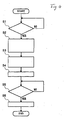
- the shift lever position detecting unit 21 detects a switchover position of the shift lever 22 to inform the CPU 31 of the range control unit 20 of the same (section S1).
- the CPU 31 starts the motor 12 so as to rotate the detent lever 5 to a position where the range engagement grooves 5d, 5e, 5f, 5g, 5h corresponding to ranges corresponding to switchover positions of the shift lever can engage with the roller 9a (section S2).
- the CPU 31 sets a duty ratio from the information about battery voltage and the information about oil temperature on the basis of TABLE of duty ratio shown in Fig. 3 (section S3).
- the duty ratio is a ratio of a movable time to a total time, for example, in a given time.
- the motor 12 rotates forward or rearward at a rotational speed corresponding to the duty ratio (section S4).
- the range control shaft 7 rotates a predetermined angle in a direction of an arrow C or an arrow D in Fig. 1 through the worm 12b, worm wheel (not shown), gear 15, two-stage gear 16, and output gear (not shown).
- the detent lever 5, pin 5a, and the arm port ion 5b also rotate in the direction of the arrow C or the arrow D.
- the spool 2a of the manual valve 2 engaging with the pin 5a via the engagement groove 2c is moved in a direction of the arrow A or the arrow B.
- the range of the manual valve 2 is sequentially switched over to the P - R - N - D - L ranges from the side of the arrow B.
- the position sensor 28 sequentially detects the range engagement grooves 5d, 5e, 5f, 5g and 5h, which engage with the roller 9a.
- the CPU 31 cuts off an electric source to the motor 12 to actuate the brake 18 (section S6) to stop the motor 12. Accordingly, the manual valve 2 is switched over to a range corresponding to the switchover range of the shift lever 21.
- the detent lever 5 stops its rotation.
- the detent lever 5 may rotate due to inertia of respective parts and stop its rotation before the roller 9a falls down into a valley of the range engagement groove or after the roller passes a valley of the range engagement groove. In such case, range switchover of the manual valve 2 may become incorrect and so switchover operation of the automatic transmission 25 may not be effected smoothly.
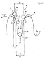
- the range switchover apparatus 1 takes account of inertia of respective parts such that when the detent lever 5 rotates in a direction of an arrow D as shown in Fig. 5, the position sensor 28 detects the roller 9a being caused by the elastic force of the detent spring 9 to pass a position where the detent lever 5 is drawn in, and an inlet 5f' of the range engagement groove (for example, the range engagement groove designated by a character 5f) coming to the roller 9a, and cuts off an electric source to the motor 12 to actuate the brake 18, thereby causing a valley 5f" to bear the roller 9a.
- the range switchover apparatus 1 takes account of inertia of respective parts such that when the detent lever 5 rotates in a direction of an arrow D as shown in Fig. 5, the position sensor 28 detects the roller 9a being caused by the elastic force of the detent spring 9 to pass a position where the detent lever 5 is drawn in, and an inlet 5f' of the range engagement groove (for example, the range engagement groove designated by
- the range engagement groove 5f bears the roller 9a in some region (a detent lever rotation stopping region W) around the valley 5f".
- the region W is set in a range of error in range switchover of the manual valve 2, and is one, in which oil pressure is generated due to the range switchover of the manual valve 2.
- the roller 9a cannot be in some cases born within the detent lever rotation stopping region W because the rotational speed of the motor 12 changes due to changes in the environment, such as fluctuation in battery voltage, influences due to heat of the working oil in the automatic transmission and the like.
- the CPU 31 further selects a duty ratio in Fig. 3 in accordance with the battery voltage and the oil temperature in the automatic transmission to control the rotational speed of the motor 12 on the basis of the duty ratio and to actuate the brake 18 in a correction region H for the braking position shown in Fig. 5 to surely bear the roller 9a within the detent lever rotation stopping region W.
- a range switchover apparatus 100 provides a clutch (driving force stopping unit) 19 in place of the brake, and stops the rotation of the detent lever 5 by releasing the clutch 19 and cutting off transmission of driving force of the drive motor.
- the range switchover apparatus 100 according to the second embodiment is constructed such that the clutch 19 is provided in place of the brake 18 in contrast to the range switchover apparatus 1 according to the illustrative embodiment and the CPU 31 controls releasing and actuation of the clutch 19, and so the same parts as those in the range switchover apparatus 1 according to the illustrative embodiment are designated by the same characters with an explanation thereof being omitted.
- the shift lever position detecting unit 21 detects a switchover position of the shift lever 22 to inform the CPU 31 of the range control unit 20 of the same (section S11).
- the CPU 31 starts the motor 12 so as to rotate the detent lever 5 to a position where the range engagement grooves 5d, 5e, 5f, 5g, 5h corresponding to ranges corresponding to switchover positions of the shift lever can engage with the roller 9a (section S12).
- the CPU 31 sets a duty ratio from the information about battery voltage and the information about oil temperature on the basis of TABLE of duty ratio shown in Fig. 3 (section S13).
- the motor 12 rotates forward or rearward at a rotational speed corresponding to the duty ratio (section S14). Then torque of the motor is transmitted to the worm 12b, worm wheel (not shown), gear 15, two-stage gear 16, output gear (not shown) and the range control shaft 7.
- the spool 2a of the manual valve 2 is moved in a direction of the arrow A of or the arrow B of the pin 5a,
- the range of the manual valve 2 is sequentially switched over to the P - R - N - D - L ranges from the side of the arrow B.
- the position sensor 28 sequentially detects the range engagement grooves 5d, 5e, 5f, 5g and 5h, which engage with the roller 9a.
- the CPU 31 releases the clutch 19 (section S19) to stop the motor 12. Accordingly, the manual valve 2 is switched over to a range corresponding to the switchover range of the shift lever 21.
- the range switchover apparatus 100 also takes account of inertia of respective parts such that as shown in Fig. 5, the position sensor 28 detects the inlet 5f' of the range engagement groove (for example, the range engagement groove designated by a character 5f) coming to the roller 9a so that the roller 9a is born in some region (a detent lever rotation stopping region W) around the valley 5f" of the range engagement groove 5f.
- the position sensor 28 detects the inlet 5f' of the range engagement groove (for example, the range engagement groove designated by a character 5f) coming to the roller 9a so that the roller 9a is born in some region (a detent lever rotation stopping region W) around the valley 5f" of the range engagement groove 5f.
- the CPU 31 selects a duty ratio in Fig. 3 in accordance with the battery voltage and the oil temperature in the automatic transmission to control the rotational speed of the motor 12 on the basis of the duty ratio. Therefore, the range switchover apparatus 100 according to the invention actuates the clutch 19 in a correction region G for the clutch release position shown in Fig. 8 to surely bear the roller 9a within the detent lever rotation stopping region W.
- a position of the detent lever 5 relative to the roller 9a at the time of actuation of the brake and at the time of release of the clutch is in the vicinity of a point E (in the vicinity of inlets 5d', 5e', 5f', 5g' and 5h') in the case where the detent lever 5 rotates in the direction of, the arrow D, and is in the vicinity of a point J (in the vicinity of the inlets 5d' , 5e' , 5f', 5g' and 5h') in the case where the detent lever rotates in the direction of the arrow C.
- the range engagement groove indicated by the character 5d is formed to have a valley of greater depth than that of the other range engagement grooves.
- the detent lever 5 is biased by the roller 9a, which is provided on the detent spring 9 with elasticity, it seems that in the case where the roller 9a abuts against an inclined surface of the range engagement groove, the detent lever is exerted by the bias of the roller 9a to rotate to enable bearing the roller 9a on the valley of the range engagement groove.
- the detent lever hardly rotates biased by the roller 9a because there is provided the worm 12b for decelerating the rotation of the motor 12.
- the rotation controlling unit adjusts the drive motor so as to make the same rotate at a predetermined rotational speed in response to a state of the environment detected by the environment detecting unit, whereby after the driving force stopping unit prevents transmission of a driving force from the drive motor to the range switchover valve operating unit, the detent mechanism can correctly hold the range switchover valve operating unit in a desired shift position to surely and smoothly perform a shift range switchover of the automatic transmission.
- the detent mechanism can correctly hold the range switchover valve operating unit in a desired shift position to correctly perform switchover of the switchover valve even when a driving force from the drive motor is not transmitted to the range switchover valve driving unit and the range switchover valve driving unit does not stop instantly.
- the range switchover valve operating unit can be correctly held in a desired shift position to correctly perform switchover of the switchover valve.
- a range switchover apparatus including a detent mechanism for holding in respective shift positions a range switchover means operating unit capable of switching over a switchover means, which switches over a shift range, among respective shift positions, a driving force stopping unit for preventing a driving force from the drive motor from being transmitted to the range switchover means operating unit, a stoppage controlling unit adapted to detect a position of the range switchover means operating unit to control the driving force stopping unit so as to hold the range switchover means operating unit in a predetermined shift position of the detent mechanism, an environment detecting unit for detecting an environment of the drive motor, and a rotation controlling unit for controlling the drive motor at a predetermined rotational speed in response to a state of the environment detected by the environment detecting unit.
- the range switchover apparatus enables surely performing switchover of a switchover means of an automatic transmission.
Landscapes
- Engineering & Computer Science (AREA)
- General Engineering & Computer Science (AREA)
- Mechanical Engineering (AREA)
- Control Of Transmission Device (AREA)
- Gear-Shifting Mechanisms (AREA)
- Arrangement Or Mounting Of Control Devices For Change-Speed Gearing (AREA)
Applications Claiming Priority (3)
| Application Number | Priority Date | Filing Date | Title |
|---|---|---|---|
| JP37150999 | 1999-12-27 | ||
| JP37150999A JP2001182828A (ja) | 1999-12-27 | 1999-12-27 | 自動変速機のレンジ切り替え装置 |
| EP00127352A EP1113195B1 (de) | 1999-12-27 | 2000-12-13 | Gerät zum Umschalten eines Bereiches für automatische Getriebe |
Related Parent Applications (1)
| Application Number | Title | Priority Date | Filing Date |
|---|---|---|---|
| EP00127352A Division EP1113195B1 (de) | 1999-12-27 | 2000-12-13 | Gerät zum Umschalten eines Bereiches für automatische Getriebe |
Publications (3)
| Publication Number | Publication Date |
|---|---|
| EP1411274A2 true EP1411274A2 (de) | 2004-04-21 |
| EP1411274A3 EP1411274A3 (de) | 2006-01-04 |
| EP1411274B1 EP1411274B1 (de) | 2008-03-05 |
Family
ID=18498832
Family Applications (2)
| Application Number | Title | Priority Date | Filing Date |
|---|---|---|---|
| EP03026382A Expired - Lifetime EP1411274B1 (de) | 1999-12-27 | 2000-12-13 | Stufenumschalteinrichtung für ein automatisches Getriebe |
| EP00127352A Expired - Lifetime EP1113195B1 (de) | 1999-12-27 | 2000-12-13 | Gerät zum Umschalten eines Bereiches für automatische Getriebe |
Family Applications After (1)
| Application Number | Title | Priority Date | Filing Date |
|---|---|---|---|
| EP00127352A Expired - Lifetime EP1113195B1 (de) | 1999-12-27 | 2000-12-13 | Gerät zum Umschalten eines Bereiches für automatische Getriebe |
Country Status (4)
| Country | Link |
|---|---|
| US (1) | US6589133B2 (de) |
| EP (2) | EP1411274B1 (de) |
| JP (1) | JP2001182828A (de) |
| DE (2) | DE60038255T2 (de) |
Cited By (1)
| Publication number | Priority date | Publication date | Assignee | Title |
|---|---|---|---|---|
| CN107179192A (zh) * | 2017-05-25 | 2017-09-19 | 武汉泛洲机械制造有限公司 | 一种用于变速箱板簧耐久试验的装置 |
Families Citing this family (17)
| Publication number | Priority date | Publication date | Assignee | Title |
|---|---|---|---|---|
| US6877390B2 (en) * | 2002-02-28 | 2005-04-12 | Aisin Aw Co., Ltd. | Shift range changeover mechanism |
| DE10215116C1 (de) * | 2002-04-05 | 2003-07-10 | Siemens Ag | Vorrichtung und Verfahren zur Bestimmung von Getriebepositionen in einem Automatikgetriebe |
| US7084597B2 (en) * | 2002-06-03 | 2006-08-01 | Denso Corporation | Motor control apparatus |
| JP2004052819A (ja) * | 2002-07-16 | 2004-02-19 | Aisin Aw Co Ltd | 車輌のレンジ切替え装置 |
| JP4748379B2 (ja) * | 2003-02-26 | 2011-08-17 | 日本精工株式会社 | 電動リニアアクチュエータ |
| JP2005207570A (ja) * | 2003-04-18 | 2005-08-04 | Aisin Aw Co Ltd | 車輌のレンジ切換え装置 |
| JP2006219034A (ja) * | 2005-02-10 | 2006-08-24 | Denso Corp | 運転許可装置 |
| JP2007170545A (ja) * | 2005-12-22 | 2007-07-05 | Denso Corp | シフトレンジ切換装置 |
| US7934590B2 (en) | 2006-06-07 | 2011-05-03 | GM Global Technology Operations LLC | Park-by-wire subsystem for a control system for an electrically variable hybrid transmission |
| DE102007005400A1 (de) * | 2007-02-03 | 2008-08-07 | Zf Friedrichshafen Ag | Verfahren zum Betreiben eines Antriebsstranges |
| JP4952541B2 (ja) * | 2007-11-28 | 2012-06-13 | トヨタ自動車株式会社 | レンジ切替装置 |
| JP6173875B2 (ja) * | 2013-10-24 | 2017-08-02 | 日立オートモティブシステムズ株式会社 | 自動変速機のレンジ切換装置 |
| JP6575336B2 (ja) * | 2015-12-07 | 2019-09-18 | 株式会社デンソー | 自動変速機用油圧制御システムの制御装置 |
| EP3507527B1 (de) | 2016-08-31 | 2026-05-06 | Cummins, Inc. | Versetzte zwischenradnabe für rückschlagkontrolle |
| CN109838551B (zh) * | 2019-03-25 | 2021-04-16 | 法可赛(太仓)汽车配件有限公司 | 换挡执行机构的控制方法、装置及换挡控制系统 |
| KR102659237B1 (ko) * | 2019-05-07 | 2024-04-18 | 현대자동차주식회사 | 시프트레버의 클러치 신호를 이용한 전자식 클러치장치의 작동 제어방법 |
| JP7188347B2 (ja) * | 2019-10-01 | 2022-12-13 | 株式会社デンソー | シフトレンジ制御装置 |
Family Cites Families (12)
| Publication number | Priority date | Publication date | Assignee | Title |
|---|---|---|---|---|
| JPS5817246A (ja) | 1981-07-23 | 1983-02-01 | Nippon Denso Co Ltd | 自動変速制御装置 |
| JPS58105828A (ja) * | 1981-12-15 | 1983-06-23 | Honda Motor Co Ltd | 自動変速機の電動式レンジ切換装置 |
| JPS61167743A (ja) | 1985-01-19 | 1986-07-29 | Toyota Motor Corp | 変速機 |
| JPH0663557B2 (ja) | 1985-01-19 | 1994-08-22 | トヨタ自動車株式会社 | 変速機の制御装置 |
| US5156243A (en) * | 1989-11-15 | 1992-10-20 | Mazda Motor Corporation | Operation apparatus for vehicle automatic transmission mechanism |
| JP2898045B2 (ja) * | 1990-03-01 | 1999-05-31 | マツダ株式会社 | 車両用自動変速機の操作装置 |
| IT1251752B (it) * | 1991-10-31 | 1995-05-23 | Fiat Auto Spa | Dispositivo elettronico per la selezione delle marce in un cambio automatico per autoveicoli |
| EP0896855B1 (de) * | 1993-10-12 | 2003-02-26 | SMC Kabushiki Kaisha | Linearantrieb |
| JP3239576B2 (ja) | 1993-12-27 | 2001-12-17 | トヨタ自動車株式会社 | 自動変速機のレンジ切換弁の制御装置 |
| JP3212216B2 (ja) * | 1994-03-22 | 2001-09-25 | 三菱電機株式会社 | 直流電動モータ式操舵装置 |
| US6157884A (en) * | 1998-09-25 | 2000-12-05 | Nissan Motor Co., Ltd. | Speed ratio control device and control method for automatic transmission |
| JP2000170905A (ja) * | 1998-09-28 | 2000-06-23 | Denso Corp | 自動変速機のシフトレンジ切換装置 |
-
1999
- 1999-12-27 JP JP37150999A patent/JP2001182828A/ja active Pending
-
2000
- 2000-12-13 DE DE60038255T patent/DE60038255T2/de not_active Expired - Lifetime
- 2000-12-13 EP EP03026382A patent/EP1411274B1/de not_active Expired - Lifetime
- 2000-12-13 EP EP00127352A patent/EP1113195B1/de not_active Expired - Lifetime
- 2000-12-13 DE DE60011741T patent/DE60011741T2/de not_active Expired - Lifetime
- 2000-12-20 US US09/750,488 patent/US6589133B2/en not_active Expired - Fee Related
Cited By (2)
| Publication number | Priority date | Publication date | Assignee | Title |
|---|---|---|---|---|
| CN107179192A (zh) * | 2017-05-25 | 2017-09-19 | 武汉泛洲机械制造有限公司 | 一种用于变速箱板簧耐久试验的装置 |
| CN107179192B (zh) * | 2017-05-25 | 2019-05-28 | 武汉泛洲机械制造有限公司 | 一种用于变速箱板簧耐久试验的装置 |
Also Published As
| Publication number | Publication date |
|---|---|
| EP1411274A3 (de) | 2006-01-04 |
| DE60011741T2 (de) | 2005-07-07 |
| EP1411274B1 (de) | 2008-03-05 |
| DE60038255D1 (de) | 2008-04-17 |
| EP1113195A1 (de) | 2001-07-04 |
| JP2001182828A (ja) | 2001-07-06 |
| EP1113195B1 (de) | 2004-06-23 |
| US20010039227A1 (en) | 2001-11-08 |
| DE60038255T2 (de) | 2009-03-19 |
| DE60011741D1 (de) | 2004-07-29 |
| US6589133B2 (en) | 2003-07-08 |
Similar Documents
| Publication | Publication Date | Title |
|---|---|---|
| EP1411274B1 (de) | Stufenumschalteinrichtung für ein automatisches Getriebe | |
| CN101341054B (zh) | 车辆的停车控制系统 | |
| JP2008128444A (ja) | 自動変速機のパーキング装置 | |
| JP2001050389A (ja) | 車両用の電動式変速機切換え装置 | |
| EP1113194B1 (de) | Positionwahleinrichtung für ein automatisches Getriebe | |
| JP2008128445A (ja) | 自動変速機のパーキング装置 | |
| EP2112408B1 (de) | Shift-by-Wire-Schaltanordnung | |
| JP2008128470A (ja) | 自動変速機のパーキング装置 | |
| JP2005132197A (ja) | オートマチック自動車のアクセルペダル装置 | |
| US7093683B2 (en) | All-terrain vehicle | |
| JP2019027553A (ja) | シフトバイワイヤ制御装置 | |
| JP4508089B2 (ja) | 車両のレンジ切換え装置 | |
| CN210531592U (zh) | 选换挡机构、变速器及车辆 | |
| JP2002310279A (ja) | 車輌のエンジンブレーキ制御方法 | |
| JP4577246B2 (ja) | レンジ切換え装置 | |
| KR100199162B1 (ko) | 자동 변속차량의 자동 브레이크 구동장치 및 그 방법 | |
| EP1207320A2 (de) | Schaltstufenanzeigeeinheit und Schaltstufenanzeigeverfahren | |
| JP3380648B2 (ja) | コンバインの走行変速装置 | |
| JP3973505B2 (ja) | 非常時切換装置付き変速装置 | |
| JPH07217719A (ja) | 車両用自動変速装置 | |
| JP3320920B2 (ja) | 坂道発進補助装置 | |
| JPH06227412A (ja) | 作業用走行車におけるステアリング駆動装置 | |
| KR100452192B1 (ko) | 자동차의 급발진 방지장치 | |
| KR100536314B1 (ko) | 자동차의 클러치페달 자동복귀장치 | |
| JP4132805B2 (ja) | 自動変速機の変速制御装置 |
Legal Events
| Date | Code | Title | Description |
|---|---|---|---|
| PUAI | Public reference made under article 153(3) epc to a published international application that has entered the european phase |
Free format text: ORIGINAL CODE: 0009012 |
|
| AC | Divisional application: reference to earlier application |
Ref document number: 1113195 Country of ref document: EP Kind code of ref document: P |
|
| AK | Designated contracting states |
Kind code of ref document: A2 Designated state(s): DE FR GB IT |
|
| PUAL | Search report despatched |
Free format text: ORIGINAL CODE: 0009013 |
|
| AK | Designated contracting states |
Kind code of ref document: A3 Designated state(s): DE FR GB IT |
|
| 17P | Request for examination filed |
Effective date: 20060704 |
|
| AKX | Designation fees paid |
Designated state(s): DE FR GB IT |
|
| GRAP | Despatch of communication of intention to grant a patent |
Free format text: ORIGINAL CODE: EPIDOSNIGR1 |
|
| GRAS | Grant fee paid |
Free format text: ORIGINAL CODE: EPIDOSNIGR3 |
|
| GRAA | (expected) grant |
Free format text: ORIGINAL CODE: 0009210 |
|
| AC | Divisional application: reference to earlier application |
Ref document number: 1113195 Country of ref document: EP Kind code of ref document: P |
|
| AK | Designated contracting states |
Kind code of ref document: B1 Designated state(s): DE FR GB IT |
|
| REG | Reference to a national code |
Ref country code: GB Ref legal event code: FG4D |
|
| REF | Corresponds to: |
Ref document number: 60038255 Country of ref document: DE Date of ref document: 20080417 Kind code of ref document: P |
|
| ET | Fr: translation filed | ||
| PLBE | No opposition filed within time limit |
Free format text: ORIGINAL CODE: 0009261 |
|
| STAA | Information on the status of an ep patent application or granted ep patent |
Free format text: STATUS: NO OPPOSITION FILED WITHIN TIME LIMIT |
|
| 26N | No opposition filed |
Effective date: 20081208 |
|
| PG25 | Lapsed in a contracting state [announced via postgrant information from national office to epo] |
Ref country code: IT Free format text: LAPSE BECAUSE OF FAILURE TO SUBMIT A TRANSLATION OF THE DESCRIPTION OR TO PAY THE FEE WITHIN THE PRESCRIBED TIME-LIMIT Effective date: 20080305 |
|
| PGFP | Annual fee paid to national office [announced via postgrant information from national office to epo] |
Ref country code: GB Payment date: 20091209 Year of fee payment: 10 Ref country code: FR Payment date: 20091221 Year of fee payment: 10 |
|
| PGFP | Annual fee paid to national office [announced via postgrant information from national office to epo] |
Ref country code: DE Payment date: 20101208 Year of fee payment: 11 |
|
| GBPC | Gb: european patent ceased through non-payment of renewal fee |
Effective date: 20101213 |
|
| REG | Reference to a national code |
Ref country code: FR Ref legal event code: ST Effective date: 20110831 |
|
| PG25 | Lapsed in a contracting state [announced via postgrant information from national office to epo] |
Ref country code: FR Free format text: LAPSE BECAUSE OF NON-PAYMENT OF DUE FEES Effective date: 20110103 |
|
| PG25 | Lapsed in a contracting state [announced via postgrant information from national office to epo] |
Ref country code: GB Free format text: LAPSE BECAUSE OF NON-PAYMENT OF DUE FEES Effective date: 20101213 |
|
| REG | Reference to a national code |
Ref country code: DE Ref legal event code: R119 Ref document number: 60038255 Country of ref document: DE Effective date: 20130702 |
|
| PG25 | Lapsed in a contracting state [announced via postgrant information from national office to epo] |
Ref country code: DE Free format text: LAPSE BECAUSE OF NON-PAYMENT OF DUE FEES Effective date: 20130702 |