EP1411296A2 - Sauerstofflanze zur Hochtemperaturvergasung von Abfällen, sowie Verfahren zum Betreiben derselben - Google Patents
Sauerstofflanze zur Hochtemperaturvergasung von Abfällen, sowie Verfahren zum Betreiben derselben Download PDFInfo
- Publication number
- EP1411296A2 EP1411296A2 EP03090302A EP03090302A EP1411296A2 EP 1411296 A2 EP1411296 A2 EP 1411296A2 EP 03090302 A EP03090302 A EP 03090302A EP 03090302 A EP03090302 A EP 03090302A EP 1411296 A2 EP1411296 A2 EP 1411296A2
- Authority
- EP
- European Patent Office
- Prior art keywords
- oxygen
- fuel
- burner
- oxygen lance
- channel
- Prior art date
- Legal status (The legal status is an assumption and is not a legal conclusion. Google has not performed a legal analysis and makes no representation as to the accuracy of the status listed.)
- Granted
Links
- QVGXLLKOCUKJST-UHFFFAOYSA-N atomic oxygen Chemical compound [O] QVGXLLKOCUKJST-UHFFFAOYSA-N 0.000 title claims abstract description 125
- 239000001301 oxygen Substances 0.000 title claims abstract description 125
- 229910052760 oxygen Inorganic materials 0.000 title claims abstract description 125
- 238000002309 gasification Methods 0.000 title claims abstract description 25
- 239000002699 waste material Substances 0.000 title claims abstract description 6
- 238000000034 method Methods 0.000 title claims description 12
- 239000000446 fuel Substances 0.000 claims abstract description 25
- 238000006243 chemical reaction Methods 0.000 claims abstract description 12
- 239000007789 gas Substances 0.000 claims description 10
- 230000015572 biosynthetic process Effects 0.000 claims description 8
- 239000000376 reactant Substances 0.000 claims description 8
- 238000003786 synthesis reaction Methods 0.000 claims description 8
- XLYOFNOQVPJJNP-UHFFFAOYSA-N water Chemical compound O XLYOFNOQVPJJNP-UHFFFAOYSA-N 0.000 claims description 7
- VNWKTOKETHGBQD-UHFFFAOYSA-N methane Chemical compound C VNWKTOKETHGBQD-UHFFFAOYSA-N 0.000 claims description 4
- 239000003344 environmental pollutant Substances 0.000 claims description 2
- 239000007788 liquid Substances 0.000 claims description 2
- 231100000719 pollutant Toxicity 0.000 claims description 2
- 239000000126 substance Substances 0.000 claims description 2
- 239000002826 coolant Substances 0.000 claims 1
- 238000002485 combustion reaction Methods 0.000 description 10
- 239000002737 fuel gas Substances 0.000 description 4
- 239000000498 cooling water Substances 0.000 description 3
- 238000011161 development Methods 0.000 description 3
- 230000018109 developmental process Effects 0.000 description 3
- 238000004200 deflagration Methods 0.000 description 2
- 238000006213 oxygenation reaction Methods 0.000 description 2
- 230000001133 acceleration Effects 0.000 description 1
- 238000009833 condensation Methods 0.000 description 1
- 230000005494 condensation Effects 0.000 description 1
- 238000010276 construction Methods 0.000 description 1
- 238000001816 cooling Methods 0.000 description 1
- 238000009792 diffusion process Methods 0.000 description 1
- 238000012423 maintenance Methods 0.000 description 1
- 239000000203 mixture Substances 0.000 description 1
- 238000004321 preservation Methods 0.000 description 1
Images


Classifications
-
- F—MECHANICAL ENGINEERING; LIGHTING; HEATING; WEAPONS; BLASTING
- F23—COMBUSTION APPARATUS; COMBUSTION PROCESSES
- F23D—BURNERS
- F23D14/00—Burners for combustion of a gas, e.g. of a gas stored under pressure as a liquid
- F23D14/32—Burners for combustion of a gas, e.g. of a gas stored under pressure as a liquid using a mixture of gaseous fuel and pure oxygen or oxygen-enriched air
-
- F—MECHANICAL ENGINEERING; LIGHTING; HEATING; WEAPONS; BLASTING
- F23—COMBUSTION APPARATUS; COMBUSTION PROCESSES
- F23G—CREMATION FURNACES; CONSUMING WASTE PRODUCTS BY COMBUSTION
- F23G5/00—Incineration of waste; Incinerator constructions; Details, accessories or control therefor
- F23G5/02—Incineration of waste; Incinerator constructions; Details, accessories or control therefor with pretreatment
- F23G5/027—Incineration of waste; Incinerator constructions; Details, accessories or control therefor with pretreatment pyrolising or gasifying stage
-
- C—CHEMISTRY; METALLURGY
- C10—PETROLEUM, GAS OR COKE INDUSTRIES; TECHNICAL GASES CONTAINING CARBON MONOXIDE; FUELS; LUBRICANTS; PEAT
- C10J—PRODUCTION OF PRODUCER GAS, WATER-GAS, SYNTHESIS GAS FROM SOLID CARBONACEOUS MATERIAL, OR MIXTURES CONTAINING THESE GASES; CARBURETTING AIR OR OTHER GASES
- C10J3/00—Production of combustible gases containing carbon monoxide from solid carbonaceous fuels
- C10J3/02—Fixed-bed gasification of lump fuel
- C10J3/20—Apparatus; Plants
-
- C—CHEMISTRY; METALLURGY
- C10—PETROLEUM, GAS OR COKE INDUSTRIES; TECHNICAL GASES CONTAINING CARBON MONOXIDE; FUELS; LUBRICANTS; PEAT
- C10J—PRODUCTION OF PRODUCER GAS, WATER-GAS, SYNTHESIS GAS FROM SOLID CARBONACEOUS MATERIAL, OR MIXTURES CONTAINING THESE GASES; CARBURETTING AIR OR OTHER GASES
- C10J2200/00—Details of gasification apparatus
- C10J2200/15—Details of feeding means
- C10J2200/152—Nozzles or lances for introducing gas, liquids or suspensions
-
- C—CHEMISTRY; METALLURGY
- C10—PETROLEUM, GAS OR COKE INDUSTRIES; TECHNICAL GASES CONTAINING CARBON MONOXIDE; FUELS; LUBRICANTS; PEAT
- C10J—PRODUCTION OF PRODUCER GAS, WATER-GAS, SYNTHESIS GAS FROM SOLID CARBONACEOUS MATERIAL, OR MIXTURES CONTAINING THESE GASES; CARBURETTING AIR OR OTHER GASES
- C10J2300/00—Details of gasification processes
- C10J2300/09—Details of the feed, e.g. feeding of spent catalyst, inert gas or halogens
- C10J2300/0953—Gasifying agents
- C10J2300/0959—Oxygen
-
- F—MECHANICAL ENGINEERING; LIGHTING; HEATING; WEAPONS; BLASTING
- F23—COMBUSTION APPARATUS; COMBUSTION PROCESSES
- F23G—CREMATION FURNACES; CONSUMING WASTE PRODUCTS BY COMBUSTION
- F23G2201/00—Pretreatment
- F23G2201/40—Gasification
-
- F—MECHANICAL ENGINEERING; LIGHTING; HEATING; WEAPONS; BLASTING
- F23—COMBUSTION APPARATUS; COMBUSTION PROCESSES
- F23K—FEEDING FUEL TO COMBUSTION APPARATUS
- F23K2900/00—Special features of, or arrangements for fuel supplies
- F23K2900/05003—Non-continuous fluid fuel supply
Definitions
- the invention relates to an oxygen lance according to the Features of the preamble of claim 1 and a method of operating the same in a high temperature reactor.
- Oxygenation to the gasification bed for example in a high temperature reactor, with the help of oxygen lances to realize.
- Oxygen lances in the the senses referred to here are water-cooled nozzles, with which usually oxygen or oxygen enriched Air in the internal combustion chamber of gasification reactors is injected.
- German patent 195 12 249 C2 teaches oxygen lances to use with at least one permanently burning pilot flame with high flame temperature and high burning speed operated in this way be that the lance oxygen at least approximately Speed of sound is accelerated whereby the lance oxygen is also extremely heated becomes.
- the high temperature of the oxygen increases the gasification rate, the strong acceleration of oxygen increases the area of influence the lance is crucial.
- an oxygen lance is used for this used with a burner for generation the pilot flame is equipped.
- This burner / oxygen lance combination stands out in particular from the fact that in addition to a first oxygen channel, the for the entry of oxygen in the Gasification bed of the reactor, a separate, second oxygen channel is provided, the supply the pilot flame generated by the burner concerned with oxygen.
- the object of the present invention is to provide a burner / oxygen lance combination as well as a procedure to indicate their use, in burner operation can be used while doing the appraisal the prior art dangers mentioned above and disadvantages.
- the channel for transporting reaction oxygen that is, the oxygen that is required to react Gasification bed of the reactor is introduced, identical is with the channel for supplying fuel oxygen, i.e. the oxygen to supply the burner or pilot flame, is particularly advantageous achieved that regardless of whether the burner / oxygen lance combination with always burning Pilot flame with or without oxygen supply the gasification bed of the reactor is always driven an oxygen flow is led through the oxygen channel is because at least the burner flame with the stoichiometric combustion necessary amount of Oxygen (fuel oxygen) is supplied.
- fuel oxygen i.e. the oxygen to supply the burner or pilot flame
- the device-like structure of the oxygen lance simplified overall with burner device, because connections and additional channels for the separate inflow of oxygen for pilot / burner flame on the one hand and the oxygen supply to the gasification bed of the reactor on the other hand.
- a control device which is the amount of oxygen supplied in at least controls two different pass states, becomes burner flame for the two operating states and supplying reaction oxygen to the gasification bed on the one hand and burner flame without feed of reaction oxygen in the gasification bed on the other hand the amount of oxygen required in each case dosed fed.
- Fuel in the sense of this entire application such as methane gas, in-process synthesis gas or individual Components of the same as well as liquid and / or pumpable, pollutant-containing substances his.
- An advantageous embodiment for a control device which is the amount of oxygen supplied in at least two different pass states controls, is the realization as in the oxygen flow valves connected in parallel. hereby becomes a robust and technically particularly simple Path to the establishment of the required forward conditions with precisely adjustable and kept constant Passage reached.
- Another development of the invention provides the reactor end of the burner / oxygen lance combination with a replaceable one To provide the burner head.
- this is advantageous because the burner head of the hot atmosphere the high temperature reactor is exposed and thus as a wearing part only for a limited service life features, so that a quick and easy interchangeability the maintenance of the oxygen lance clearly simplified.
- the interchangeability of such a burner head especially through the Property of the invention favors that by the saving of supply channels of the invention constructive construction of the oxygen lance on the reactor side final burner head and the connection between burner head and oxygen lance in their structure is significantly simplified. So he can Burner head through a plug or screw connection be realized, which in spatial agreement with the channels of the oxygen lance stands.
- An advantageous development of the method for Operating the oxygen lance provides for the control device between the two operating states to switch pulsating. That way that through the oxygen lance into the gasification bed of the reactor entered reaction oxygen pulsating entered so that there is the advantage that channels in the gasification bed which are from the oxygen jet the lance may have been formed in the pulse breaks break down. Thus "bridging" avoided in the gasification bed.
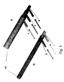
- Fig. 1 shows a schematic representation of an oxygen lance for high temperature gasification more heterogeneous Waste according to the state of the art (A) and as an exemplary embodiment of the present invention (B) in Juxtaposition.
- B is the fuel supply channel I inside. It surrounds him a single oxygen channel II, to which the separate feed channels known from the prior art for fuel oxygen and reaction oxygen are summarized.
- the burner / oxygen lance combination B only used in burner operation without oxygen as a reactant in the combustion bed of the reactor should be introduced, so the fuel channel I and the oxygen channel II each so much Fuel or oxygen, as for stoichiometric Burning in the pilot flame of the burner is needed, the pressure of oxygen for the burner is selected so that it is always above the partial pressure in the high temperature reactor, so that hot syngas enters the Oxygenation is excluded. Should be additional Oxygen as reactive oxygen in the Combustion bed of the reactor get, so will more oxygen is supplied in oxygen channel II.
- the feed is from that in this figure Control device not shown provided.
- Fig. 2 shows a longitudinal section through a more detailed Embodiment of an inventive Burner / oxygen lance combination.
- the channel for supplying fuel gas I and the channel to supply oxygen II, which is the channel for Fuel surrounds, so that pipes inside each other arise. This becomes particularly clear in the cross section shown along the right Axis A-A.
- connection valves which are separate here to the control valves and the flow connection between the valves and the feed channels shown.
- water cooling system consisting of a supply nozzle 11 and feed-through channels 4 and 5 such that the water along the main axis of the oxygen lance first of all along the lance tube to the tip of the burner 1 inserted and then from the burner tip 1 in the opposite direction.
- the burner tip 1 is through a plug connection attached to the lance tube 2 and has a funnel-shaped Sinking on which is from the reactor side End of the burner tip to the lower one Mouth of the feed pipe for fuel I tapered.
- the burner tip is designed so that the cooling water channel that separates the water from the Spends reactor side facing the burner tip is connected in terms of flow to the cooling water channel, which the water in the opposite direction leads. This is achieved through an appropriate design the burner tip through small, with the cooling water channels tightly fitting when plugged in Channels with channel walls 31, 32.
- Fig. 3 shows an embodiment for an inventive Control device, which by two in Valves IV and V connected in parallel with oxygen flow is realized and also a valve VI for control the separate fuel supply.
- the oxygen flows into the left distributor and divides into a first and a second stream of oxygen.
- the first flow of oxygen is in its flow rate from the valve controlled for the fuel oxygen V during the second flow of oxygen in its quantity through the valve is determined for the reaction oxygen IV. After passing the valves, they unite two oxygen flows back to a current that then exits the control device. It can by closing valve IV and that accordingly wide openings of the valve V the oxygen in of the amount to be dosed as for stoichiometric Burning in the pilot flame of the burner is required is, this pressure always above the partial pressure must be in the high temperature reactor. to Preservation of the stoichiometric combustion ratio must therefore open the valve VI, which Supply of fuel gas controls, set accordingly become.
- Opening valve IV Additional oxygen, which is related to the Combustion in the pilot flame in superstoichiometric Amount supplied and thus as a reactant in the Gasification bed of the reactor should get through Opening valve IV can be added.
- the pulsating Switch between the aforementioned first operating mode ("burner only”) and the second operating mode ("Burner and reaction oxygen supply”) can by pulsating opening and closing of the valve IV can be realized in the simplest way.
Landscapes
- Engineering & Computer Science (AREA)
- Chemical & Material Sciences (AREA)
- Mechanical Engineering (AREA)
- Combustion & Propulsion (AREA)
- General Engineering & Computer Science (AREA)
- Oil, Petroleum & Natural Gas (AREA)
- Organic Chemistry (AREA)
- Air Supply (AREA)
- Gasification And Melting Of Waste (AREA)
- Processing Of Solid Wastes (AREA)
- Regulation And Control Of Combustion (AREA)
- Gas Burners (AREA)
- Incineration Of Waste (AREA)
Abstract
Description
- Fig. 1
- eine schematische Darstellung einer Sauerstofflanze zur Hochtemperaturvergasung heterogener Abfälle nach dem Stand der Technik (A) sowie einer erfindungsgemäßen Sauerstofflanze zum selben Zweck (B);
- Fig. 2
- einen Längs- und einen Querschnitt durch eine detailliertere Ausführungsform einer Sauerstofflanze als Ausführungsbeispiel der Erfindung mit auswechselbarem Brennerkopf; sowie
- Fig. 3
- eine Darstellung einer durch zwei im Sauerstoffstrom parallel geschaltete Ventile implementierten Steuervorrichtung mit einem weiteren Ventil zur Zuführung von Brenngas.
Claims (11)
- Sauerstofflanze zur Hochtemperaturvergasung ggf. thermisch vorbehandelter heterogener Abfälle, mit Kanälen (I, II, III) zum Transport von Reaktionssauerstoff, zur Zuführung von Brennstoff und zur Zuführung von Brennsauerstoff,
dadurch gekennzeichnet, dass
der Kanal zum Transport von Reaktionssauerstoff (III) identisch ist mit dem Kanal zur Zuführung von Brennsauerstoff (II) und eine Steuervorrichtung enthalten ist, welche die Menge des zugeführten Sauerstoffes in mindestens zwei verschiedenen Durchlass-Zuständen steuert. - Sauerstofflanze nach Anspruch 1, dadurch gekennzeichnet, dass die Steuervorrichtung im Sauerstoffstrom parallel geschaltete Ventile (IV, V) aufweist.
- Sauerstofflanze nach einem der Ansprüche 1 oder 2, dadurch gekennzeichnet, dass reaktandenaustrittsseitig ein auswechselbarer Brennerkopf (1) vorgesehen ist.
- Sauerstofflanze nach Anspruch 3, dadurch gekennzeichnet, dass der Brennerkopf (1) durch eine Steck- oder eine Schraubverbindung (31, 32) befestigt ist.
- Sauerstofflanze nach einem der Ansprüche 1 bis 4, dadurch gekennzeichnet, dass die Kanäle (I, II) in axialer Richtung konzentrisch ineinanderliegend verlaufen.
- Sauerstofflanze nach einem der Ansprüche 1 bis 5, dadurch gekennzeichnet, dass zusätzlich Kühlmittelkanäle (4, 5) vorgesehen sind.
- Verfahren zum Betreiben einer Sauerstofflanze nach einem der Ansprüche 1 bis 6 in einem Hochtemperaturreaktor,
dadurch gekennzeichnet, dass
die Sauerstofflanze permanent mit mindestens einer Brennerflamme betrieben wird undwobei stets der Druck des Sauerstoffs so gewählt wird, dass er größer ist als der Partialdruck im Hochtemperaturreaktor.in einer ersten Betriebsart die Reaktanden Brennstoff und Sauerstoff in näherungsweise stöchiometrischem Verhältnis für die Brennerflamme zugeführt werden,in einer zweiten Betriebsart der Sauerstoff in überstöchiometrischem Verhältnis zum Brennstoff zugeführt wird, sodass dieser Anteil des Sauerstoffs als Reaktionspartner in den Hochtemperaturreaktor gelangt, - Verfahren nach Anspruch 7, dadurch gekennzeichnet, dass zwischen der ersten Betriebsart und der zweiten Betriebsart pulsierend umgeschaltet wird.
- Verfahren nach einem der Ansprüche 7 oder 8, dadurch gekennzeichnet, dass als Brennstoff Methangas ausgewählt wird.
- Verfahren nach einem der Ansprüche 7 oder 8, dadurch gekennzeichnet, dass als Brennstoff prozesseigenes Synthesegas oder einzelne Bestandteile desselben ausgewählt wird.
- Verfahren nach einem der Ansprüche 7 oder 8, dadurch gekennzeichnet, dass als Brennstoff auch flüssige und/oder pumpfähige, schadstoffenthaltende Substanzen ausgewählt werden.
Priority Applications (1)
| Application Number | Priority Date | Filing Date | Title |
|---|---|---|---|
| SI200332034T SI1411296T1 (sl) | 2002-10-14 | 2003-09-18 | Kisikova sulica za visoko temperaturno uplinjanje odpadkov in postopek delovanja |
Applications Claiming Priority (2)
| Application Number | Priority Date | Filing Date | Title |
|---|---|---|---|
| DE10248530A DE10248530B4 (de) | 2002-10-14 | 2002-10-14 | Sauerstofflanze zur Hochtemperaturvergasung von Abfällen, sowie Verfahren zum Betreiben derselben |
| DE10248530 | 2002-10-14 |
Publications (3)
| Publication Number | Publication Date |
|---|---|
| EP1411296A2 true EP1411296A2 (de) | 2004-04-21 |
| EP1411296A3 EP1411296A3 (de) | 2006-08-02 |
| EP1411296B1 EP1411296B1 (de) | 2011-05-25 |
Family
ID=32038748
Family Applications (1)
| Application Number | Title | Priority Date | Filing Date |
|---|---|---|---|
| EP03090302A Expired - Lifetime EP1411296B1 (de) | 2002-10-14 | 2003-09-18 | Sauerstofflanze zur Hochtemperaturvergasung von Abfällen, sowie Verfahren zum Betreiben derselben |
Country Status (9)
| Country | Link |
|---|---|
| EP (1) | EP1411296B1 (de) |
| JP (1) | JP4276041B2 (de) |
| KR (1) | KR101096316B1 (de) |
| AT (1) | ATE511063T1 (de) |
| DE (1) | DE10248530B4 (de) |
| DK (1) | DK1411296T3 (de) |
| ES (1) | ES2372001T3 (de) |
| PT (1) | PT1411296E (de) |
| SI (1) | SI1411296T1 (de) |
Cited By (1)
| Publication number | Priority date | Publication date | Assignee | Title |
|---|---|---|---|---|
| WO2006113229A1 (en) * | 2005-04-18 | 2006-10-26 | General Electric Company | Improved feed indjector for gasification and related method |
Citations (1)
| Publication number | Priority date | Publication date | Assignee | Title |
|---|---|---|---|---|
| DE19512249C2 (de) | 1994-06-10 | 1996-11-07 | Thermoselect Ag | Verfahren zum Betreiben einer Sauerstofflanze bei der Hochtemperaturvergasung heterogener Abfälle |
Family Cites Families (7)
| Publication number | Priority date | Publication date | Assignee | Title |
|---|---|---|---|---|
| DE1152783B (de) * | 1961-08-28 | 1963-08-14 | Metallgesellschaft Ag | Brenner zur thermischen Umsetzung von gasfoermigen und/oder dampffoermigen bzw. fluessigen Kohlenwasserstoffen und/oder sonstigen Brenngasen mit sauerstoffhaltigen Gasen und Verfahren zum Betrieb des Brenners |
| DE2703921C3 (de) * | 1977-01-31 | 1980-09-11 | Basf Ag, 6700 Ludwigshafen | Verfahren zur Inbetriebnahme oder Herstellung der Betriebsbereitschaft eines Reaktors für die partielle Oxidation von schwerflüchtigen flüssigen oder festen Brennstoffen |
| GB2151348B (en) * | 1983-12-09 | 1986-08-06 | Shell Int Research | Burner and process for producing synthesis gas from hydrocarbon fuel |
| JPH0629659B2 (ja) | 1985-11-15 | 1994-04-20 | 日本酸素株式会社 | 高温酸素ランス |
| DE19637195C2 (de) * | 1996-02-16 | 1998-12-17 | Thermoselect Ag | Verfahren zum Betreiben eines Hochtemperaturreaktors zur Behandlung von Entsorgungsgütern |
| US6005149A (en) * | 1998-08-18 | 1999-12-21 | Engineering, Separation & Recycling, Ltd. Co. | Method and apparatus for processing organic materials to produce chemical gases and carbon char |
| JP3738141B2 (ja) * | 1998-11-10 | 2006-01-25 | 岩谷産業株式会社 | 酸素富化率可変バーナ |
-
2002
- 2002-10-14 DE DE10248530A patent/DE10248530B4/de not_active Expired - Fee Related
-
2003
- 2003-09-18 AT AT03090302T patent/ATE511063T1/de active
- 2003-09-18 EP EP03090302A patent/EP1411296B1/de not_active Expired - Lifetime
- 2003-09-18 PT PT03090302T patent/PT1411296E/pt unknown
- 2003-09-18 ES ES03090302T patent/ES2372001T3/es not_active Expired - Lifetime
- 2003-09-18 SI SI200332034T patent/SI1411296T1/sl unknown
- 2003-09-18 DK DK03090302.5T patent/DK1411296T3/da active
- 2003-10-07 JP JP2003347773A patent/JP4276041B2/ja not_active Expired - Fee Related
- 2003-10-14 KR KR1020030071355A patent/KR101096316B1/ko not_active Expired - Fee Related
Patent Citations (1)
| Publication number | Priority date | Publication date | Assignee | Title |
|---|---|---|---|---|
| DE19512249C2 (de) | 1994-06-10 | 1996-11-07 | Thermoselect Ag | Verfahren zum Betreiben einer Sauerstofflanze bei der Hochtemperaturvergasung heterogener Abfälle |
Cited By (1)
| Publication number | Priority date | Publication date | Assignee | Title |
|---|---|---|---|---|
| WO2006113229A1 (en) * | 2005-04-18 | 2006-10-26 | General Electric Company | Improved feed indjector for gasification and related method |
Also Published As
| Publication number | Publication date |
|---|---|
| KR101096316B1 (ko) | 2011-12-20 |
| DE10248530A1 (de) | 2004-04-22 |
| ES2372001T3 (es) | 2012-01-12 |
| KR20040034444A (ko) | 2004-04-28 |
| SI1411296T1 (sl) | 2011-09-30 |
| JP2004132693A (ja) | 2004-04-30 |
| PT1411296E (pt) | 2011-08-11 |
| ATE511063T1 (de) | 2011-06-15 |
| JP4276041B2 (ja) | 2009-06-10 |
| EP1411296B1 (de) | 2011-05-25 |
| DK1411296T3 (da) | 2011-08-29 |
| EP1411296A3 (de) | 2006-08-02 |
| DE10248530B4 (de) | 2004-08-12 |
Similar Documents
| Publication | Publication Date | Title |
|---|---|---|
| DE3209185C2 (de) | ||
| DE102017001025B4 (de) | Verbrennungsanlage und Verfahren zur Abgasbehandlung | |
| DE69815755T2 (de) | Reduktion von NOx-Emissionen bei Glasschmelzöfen | |
| DE2658847A1 (de) | Brennereinrichtung | |
| EP2202460A2 (de) | Flachflammenbrenner und Verfahren zum Betreiben eines Flachflammenbrenners | |
| DE2810450A1 (de) | Abschmelzender thermischer schweissbrenner | |
| EP0256063A1 (de) | Verfahren zum betreiben eines gas-infrarotstrahlers und gas-infrarotstrahler. | |
| EP4008955B1 (de) | Vorrichtung und verfahren zur verbrennungsluftzufuhr und abgasrezirkulation für einen brenner | |
| EP1446610A1 (de) | Verbrennungsverfahren, insbesondere für verfahren zur erzeugung von elektrischem strom und/oder von wärme | |
| DE69900588T2 (de) | Verfahren und vorrichtung zum fördern vorgemischten gases zu einblasdüsen eines elektro-lichtbogenofen | |
| EP0352342B1 (de) | Brenner für Trocknungs- oder Gasreinigungsprozesse | |
| EP1411296B1 (de) | Sauerstofflanze zur Hochtemperaturvergasung von Abfällen, sowie Verfahren zum Betreiben derselben | |
| EP3246558B1 (de) | Verfahren zum betreiben eines raketenantriebssystems und raketenantriebssystem | |
| DE2855499C2 (de) | Aufblaslanze | |
| DE2836345C2 (de) | Anlage zur Rußherstellung | |
| DE60012291T2 (de) | Verfahren zur Rückgewinnung von Schwefelverbindungen | |
| DE2530170A1 (de) | Industriebrenner | |
| DE1152783B (de) | Brenner zur thermischen Umsetzung von gasfoermigen und/oder dampffoermigen bzw. fluessigen Kohlenwasserstoffen und/oder sonstigen Brenngasen mit sauerstoffhaltigen Gasen und Verfahren zum Betrieb des Brenners | |
| DE921924C (de) | Schaelbrenner zur Oberflaechenbehandlung metallischer Werkstuecke | |
| DE2134100A1 (de) | Gas-luft-mischer fuer schutzgasanlagen | |
| EP0687859B1 (de) | Schneidbrenner | |
| WO1990012987A1 (de) | Vorrichtung zur zuführung von brenn- und zusatzstoffen in brenneranordnungen | |
| WO2005095857A1 (de) | Gasinjektor | |
| DE2013145C3 (de) | Brennerlanze | |
| EP4214167B1 (de) | Verfahren zum beheizen einer glasschmelze |
Legal Events
| Date | Code | Title | Description |
|---|---|---|---|
| PUAI | Public reference made under article 153(3) epc to a published international application that has entered the european phase |
Free format text: ORIGINAL CODE: 0009012 |
|
| AK | Designated contracting states |
Kind code of ref document: A2 Designated state(s): AT BE BG CH CY CZ DE DK EE ES FI FR GB GR HU IE IT LI LU MC NL PT RO SE SI SK TR |
|
| AX | Request for extension of the european patent |
Extension state: AL LT LV MK |
|
| PUAL | Search report despatched |
Free format text: ORIGINAL CODE: 0009013 |
|
| AK | Designated contracting states |
Kind code of ref document: A3 Designated state(s): AT BE BG CH CY CZ DE DK EE ES FI FR GB GR HU IE IT LI LU MC NL PT RO SE SI SK TR |
|
| AX | Request for extension of the european patent |
Extension state: AL LT LV MK |
|
| 17P | Request for examination filed |
Effective date: 20070129 |
|
| AKX | Designation fees paid |
Designated state(s): AT BE BG CH CY CZ DE DK EE ES FI FR GB GR HU IE IT LI LU MC NL PT RO SE SI SK TR |
|
| GRAP | Despatch of communication of intention to grant a patent |
Free format text: ORIGINAL CODE: EPIDOSNIGR1 |
|
| GRAS | Grant fee paid |
Free format text: ORIGINAL CODE: EPIDOSNIGR3 |
|
| GRAA | (expected) grant |
Free format text: ORIGINAL CODE: 0009210 |
|
| AK | Designated contracting states |
Kind code of ref document: B1 Designated state(s): AT BE BG CH CY CZ DE DK EE ES FI FR GB GR HU IE IT LI LU MC NL PT RO SE SI SK TR |
|
| REG | Reference to a national code |
Ref country code: GB Ref legal event code: FG4D Free format text: NOT ENGLISH |
|
| REG | Reference to a national code |
Ref country code: CH Ref legal event code: EP |
|
| REG | Reference to a national code |
Ref country code: IE Ref legal event code: FG4D Free format text: LANGUAGE OF EP DOCUMENT: GERMAN |
|
| REG | Reference to a national code |
Ref country code: DE Ref legal event code: R096 Ref document number: 50313711 Country of ref document: DE Effective date: 20110707 |
|
| REG | Reference to a national code |
Ref country code: PT Ref legal event code: SC4A Free format text: AVAILABILITY OF NATIONAL TRANSLATION Effective date: 20110728 |
|
| REG | Reference to a national code |
Ref country code: CH Ref legal event code: NV Representative=s name: TROESCH SCHEIDEGGER WERNER AG |
|
| REG | Reference to a national code |
Ref country code: RO Ref legal event code: EPE |
|
| REG | Reference to a national code |
Ref country code: SE Ref legal event code: TRGR |
|
| REG | Reference to a national code |
Ref country code: DK Ref legal event code: T3 |
|
| REG | Reference to a national code |
Ref country code: NL Ref legal event code: T3 |
|
| REG | Reference to a national code |
Ref country code: GR Ref legal event code: EP Ref document number: 20110402011 Country of ref document: GR Effective date: 20110916 |
|
| PGFP | Annual fee paid to national office [announced via postgrant information from national office to epo] |
Ref country code: CH Payment date: 20110923 Year of fee payment: 9 Ref country code: DK Payment date: 20110926 Year of fee payment: 9 |
|
| REG | Reference to a national code |
Ref country code: SK Ref legal event code: T3 Ref document number: E 9926 Country of ref document: SK |
|
| PG25 | Lapsed in a contracting state [announced via postgrant information from national office to epo] |
Ref country code: CY Free format text: LAPSE BECAUSE OF FAILURE TO SUBMIT A TRANSLATION OF THE DESCRIPTION OR TO PAY THE FEE WITHIN THE PRESCRIBED TIME-LIMIT Effective date: 20110525 |
|
| REG | Reference to a national code |
Ref country code: ES Ref legal event code: FG2A Ref document number: 2372001 Country of ref document: ES Kind code of ref document: T3 Effective date: 20120112 |
|
| REG | Reference to a national code |
Ref country code: HU Ref legal event code: AG4A Ref document number: E011983 Country of ref document: HU |
|
| PG25 | Lapsed in a contracting state [announced via postgrant information from national office to epo] |
Ref country code: EE Free format text: LAPSE BECAUSE OF FAILURE TO SUBMIT A TRANSLATION OF THE DESCRIPTION OR TO PAY THE FEE WITHIN THE PRESCRIBED TIME-LIMIT Effective date: 20110525 |
|
| PLBE | No opposition filed within time limit |
Free format text: ORIGINAL CODE: 0009261 |
|
| STAA | Information on the status of an ep patent application or granted ep patent |
Free format text: STATUS: NO OPPOSITION FILED WITHIN TIME LIMIT |
|
| PG25 | Lapsed in a contracting state [announced via postgrant information from national office to epo] |
Ref country code: CZ Free format text: LAPSE BECAUSE OF NON-PAYMENT OF DUE FEES Effective date: 20110918 Ref country code: MC Free format text: LAPSE BECAUSE OF NON-PAYMENT OF DUE FEES Effective date: 20110930 |
|
| 26N | No opposition filed |
Effective date: 20120228 |
|
| REG | Reference to a national code |
Ref country code: GR Ref legal event code: ML Ref document number: 20110402011 Country of ref document: GR Effective date: 20120403 |
|
| PG25 | Lapsed in a contracting state [announced via postgrant information from national office to epo] |
Ref country code: FI Free format text: LAPSE BECAUSE OF NON-PAYMENT OF DUE FEES Effective date: 20110918 |
|
| REG | Reference to a national code |
Ref country code: SI Ref legal event code: KO00 Effective date: 20120420 |
|
| REG | Reference to a national code |
Ref country code: SK Ref legal event code: MM4A Ref document number: E 9926 Country of ref document: SK Effective date: 20110918 |
|
| REG | Reference to a national code |
Ref country code: DE Ref legal event code: R097 Ref document number: 50313711 Country of ref document: DE Effective date: 20120228 |
|
| REG | Reference to a national code |
Ref country code: PT Ref legal event code: MM4A Free format text: LAPSE DUE TO NON-PAYMENT OF FEES Effective date: 20120619 |
|
| REG | Reference to a national code |
Ref country code: SE Ref legal event code: EUG |
|
| PG25 | Lapsed in a contracting state [announced via postgrant information from national office to epo] |
Ref country code: SK Free format text: LAPSE BECAUSE OF NON-PAYMENT OF DUE FEES Effective date: 20110918 |
|
| PG25 | Lapsed in a contracting state [announced via postgrant information from national office to epo] |
Ref country code: GR Free format text: LAPSE BECAUSE OF NON-PAYMENT OF DUE FEES Effective date: 20120403 Ref country code: PT Free format text: LAPSE BECAUSE OF NON-PAYMENT OF DUE FEES Effective date: 20120619 |
|
| PG25 | Lapsed in a contracting state [announced via postgrant information from national office to epo] |
Ref country code: SI Free format text: LAPSE BECAUSE OF NON-PAYMENT OF DUE FEES Effective date: 20110919 Ref country code: RO Free format text: LAPSE BECAUSE OF NON-PAYMENT OF DUE FEES Effective date: 20110525 |
|
| PGFP | Annual fee paid to national office [announced via postgrant information from national office to epo] |
Ref country code: BE Payment date: 20120920 Year of fee payment: 10 |
|
| PG25 | Lapsed in a contracting state [announced via postgrant information from national office to epo] |
Ref country code: SE Free format text: LAPSE BECAUSE OF NON-PAYMENT OF DUE FEES Effective date: 20110919 |
|
| PG25 | Lapsed in a contracting state [announced via postgrant information from national office to epo] |
Ref country code: LU Free format text: LAPSE BECAUSE OF NON-PAYMENT OF DUE FEES Effective date: 20110918 |
|
| PG25 | Lapsed in a contracting state [announced via postgrant information from national office to epo] |
Ref country code: BG Free format text: LAPSE BECAUSE OF FAILURE TO SUBMIT A TRANSLATION OF THE DESCRIPTION OR TO PAY THE FEE WITHIN THE PRESCRIBED TIME-LIMIT Effective date: 20110825 |
|
| PGFP | Annual fee paid to national office [announced via postgrant information from national office to epo] |
Ref country code: ES Payment date: 20130927 Year of fee payment: 11 |
|
| PGFP | Annual fee paid to national office [announced via postgrant information from national office to epo] |
Ref country code: FR Payment date: 20130919 Year of fee payment: 11 Ref country code: TR Payment date: 20130913 Year of fee payment: 11 |
|
| PGFP | Annual fee paid to national office [announced via postgrant information from national office to epo] |
Ref country code: IT Payment date: 20130923 Year of fee payment: 11 |
|
| BERE | Be: lapsed |
Owner name: THERMOSELECT AKTIENGESELLSCHAFT Effective date: 20130930 |
|
| REG | Reference to a national code |
Ref country code: CH Ref legal event code: PL |
|
| REG | Reference to a national code |
Ref country code: DK Ref legal event code: EBP Effective date: 20130930 |
|
| PG25 | Lapsed in a contracting state [announced via postgrant information from national office to epo] |
Ref country code: CH Free format text: LAPSE BECAUSE OF NON-PAYMENT OF DUE FEES Effective date: 20130930 Ref country code: LI Free format text: LAPSE BECAUSE OF NON-PAYMENT OF DUE FEES Effective date: 20130930 Ref country code: BE Free format text: LAPSE BECAUSE OF NON-PAYMENT OF DUE FEES Effective date: 20130930 |
|
| PG25 | Lapsed in a contracting state [announced via postgrant information from national office to epo] |
Ref country code: DK Free format text: LAPSE BECAUSE OF NON-PAYMENT OF DUE FEES Effective date: 20130930 |
|
| PGFP | Annual fee paid to national office [announced via postgrant information from national office to epo] |
Ref country code: IE Payment date: 20140918 Year of fee payment: 12 |
|
| PGFP | Annual fee paid to national office [announced via postgrant information from national office to epo] |
Ref country code: GB Payment date: 20140919 Year of fee payment: 12 |
|
| PGFP | Annual fee paid to national office [announced via postgrant information from national office to epo] |
Ref country code: NL Payment date: 20140918 Year of fee payment: 12 |
|
| REG | Reference to a national code |
Ref country code: FR Ref legal event code: ST Effective date: 20150529 |
|
| PG25 | Lapsed in a contracting state [announced via postgrant information from national office to epo] |
Ref country code: FR Free format text: LAPSE BECAUSE OF NON-PAYMENT OF DUE FEES Effective date: 20140930 Ref country code: IT Free format text: LAPSE BECAUSE OF NON-PAYMENT OF DUE FEES Effective date: 20140918 |
|
| GBPC | Gb: european patent ceased through non-payment of renewal fee |
Effective date: 20150918 |
|
| REG | Reference to a national code |
Ref country code: NL Ref legal event code: MM Effective date: 20151001 |
|
| REG | Reference to a national code |
Ref country code: IE Ref legal event code: MM4A |
|
| PG25 | Lapsed in a contracting state [announced via postgrant information from national office to epo] |
Ref country code: ES Free format text: LAPSE BECAUSE OF NON-PAYMENT OF DUE FEES Effective date: 20140919 Ref country code: IE Free format text: LAPSE BECAUSE OF NON-PAYMENT OF DUE FEES Effective date: 20150918 Ref country code: GB Free format text: LAPSE BECAUSE OF NON-PAYMENT OF DUE FEES Effective date: 20150918 |
|
| PG25 | Lapsed in a contracting state [announced via postgrant information from national office to epo] |
Ref country code: NL Free format text: LAPSE BECAUSE OF NON-PAYMENT OF DUE FEES Effective date: 20151001 |
|
| PGFP | Annual fee paid to national office [announced via postgrant information from national office to epo] |
Ref country code: HU Payment date: 20160915 Year of fee payment: 14 Ref country code: AT Payment date: 20160921 Year of fee payment: 14 |
|
| PGFP | Annual fee paid to national office [announced via postgrant information from national office to epo] |
Ref country code: DE Payment date: 20160929 Year of fee payment: 14 |
|
| PG25 | Lapsed in a contracting state [announced via postgrant information from national office to epo] |
Ref country code: TR Free format text: LAPSE BECAUSE OF NON-PAYMENT OF DUE FEES Effective date: 20150918 |
|
| REG | Reference to a national code |
Ref country code: DE Ref legal event code: R119 Ref document number: 50313711 Country of ref document: DE |
|
| REG | Reference to a national code |
Ref country code: AT Ref legal event code: MM01 Ref document number: 511063 Country of ref document: AT Kind code of ref document: T Effective date: 20170918 |
|
| PG25 | Lapsed in a contracting state [announced via postgrant information from national office to epo] |
Ref country code: DE Free format text: LAPSE BECAUSE OF NON-PAYMENT OF DUE FEES Effective date: 20180404 |
|
| PG25 | Lapsed in a contracting state [announced via postgrant information from national office to epo] |
Ref country code: AT Free format text: LAPSE BECAUSE OF NON-PAYMENT OF DUE FEES Effective date: 20170918 Ref country code: HU Free format text: LAPSE BECAUSE OF NON-PAYMENT OF DUE FEES Effective date: 20170919 |