EP1411367A2 - Bobine à gradient pour l'imagerie par résonance magnétique - Google Patents
Bobine à gradient pour l'imagerie par résonance magnétique Download PDFInfo
- Publication number
- EP1411367A2 EP1411367A2 EP03256514A EP03256514A EP1411367A2 EP 1411367 A2 EP1411367 A2 EP 1411367A2 EP 03256514 A EP03256514 A EP 03256514A EP 03256514 A EP03256514 A EP 03256514A EP 1411367 A2 EP1411367 A2 EP 1411367A2
- Authority
- EP
- European Patent Office
- Prior art keywords
- coil
- gradient coil
- field
- view
- gradient
- Prior art date
- Legal status (The legal status is an assumption and is not a legal conclusion. Google has not performed a legal analysis and makes no representation as to the accuracy of the status listed.)
- Granted
Links
- 238000002595 magnetic resonance imaging Methods 0.000 title description 15
- 238000000034 method Methods 0.000 claims abstract description 51
- 238000003384 imaging method Methods 0.000 claims abstract description 39
- 239000004020 conductor Substances 0.000 claims description 7
- 230000008021 deposition Effects 0.000 abstract description 10
- 238000004804 winding Methods 0.000 description 21
- 230000008569 process Effects 0.000 description 11
- 230000006870 function Effects 0.000 description 8
- 238000005481 NMR spectroscopy Methods 0.000 description 7
- 238000004590 computer program Methods 0.000 description 5
- 230000007383 nerve stimulation Effects 0.000 description 5
- 210000000578 peripheral nerve Anatomy 0.000 description 4
- 230000008901 benefit Effects 0.000 description 2
- 230000015572 biosynthetic process Effects 0.000 description 2
- 230000000694 effects Effects 0.000 description 2
- 230000005284 excitation Effects 0.000 description 2
- 238000010438 heat treatment Methods 0.000 description 2
- 238000004519 manufacturing process Methods 0.000 description 2
- 230000007246 mechanism Effects 0.000 description 2
- 238000001208 nuclear magnetic resonance pulse sequence Methods 0.000 description 2
- 230000001105 regulatory effect Effects 0.000 description 2
- 238000010079 rubber tapping Methods 0.000 description 2
- 238000000926 separation method Methods 0.000 description 2
- 239000000126 substance Substances 0.000 description 2
- 210000001015 abdomen Anatomy 0.000 description 1
- 238000003491 array Methods 0.000 description 1
- 230000009286 beneficial effect Effects 0.000 description 1
- 230000033228 biological regulation Effects 0.000 description 1
- 230000005540 biological transmission Effects 0.000 description 1
- 230000000747 cardiac effect Effects 0.000 description 1
- 230000008859 change Effects 0.000 description 1
- 230000001010 compromised effect Effects 0.000 description 1
- 238000010276 construction Methods 0.000 description 1
- 230000001276 controlling effect Effects 0.000 description 1
- 230000007812 deficiency Effects 0.000 description 1
- 230000001419 dependent effect Effects 0.000 description 1
- 229940079593 drug Drugs 0.000 description 1
- 239000003814 drug Substances 0.000 description 1
- 230000009977 dual effect Effects 0.000 description 1
- 238000009429 electrical wiring Methods 0.000 description 1
- 230000005670 electromagnetic radiation Effects 0.000 description 1
- 239000000835 fiber Substances 0.000 description 1
- 230000020169 heat generation Effects 0.000 description 1
- 238000002955 isolation Methods 0.000 description 1
- 230000004807 localization Effects 0.000 description 1
- 230000005415 magnetization Effects 0.000 description 1
- 238000005259 measurement Methods 0.000 description 1
- 210000005036 nerve Anatomy 0.000 description 1
- 238000013421 nuclear magnetic resonance imaging Methods 0.000 description 1
- 230000001766 physiological effect Effects 0.000 description 1
- 230000009467 reduction Effects 0.000 description 1
- 230000000241 respiratory effect Effects 0.000 description 1
- 230000004044 response Effects 0.000 description 1
- 239000007787 solid Substances 0.000 description 1
- 230000003068 static effect Effects 0.000 description 1
- 230000000638 stimulation Effects 0.000 description 1
Images


Classifications
-
- G—PHYSICS
- G01—MEASURING; TESTING
- G01R—MEASURING ELECTRIC VARIABLES; MEASURING MAGNETIC VARIABLES
- G01R33/00—Arrangements or instruments for measuring magnetic variables
- G01R33/20—Arrangements or instruments for measuring magnetic variables involving magnetic resonance
- G01R33/28—Details of apparatus provided for in groups G01R33/44 - G01R33/64
- G01R33/38—Systems for generation, homogenisation or stabilisation of the main or gradient magnetic field
- G01R33/385—Systems for generation, homogenisation or stabilisation of the main or gradient magnetic field using gradient magnetic field coils
Definitions
- the field of the invention is nuclear magnetic resonance (NMR) imaging methods and systems. More particularly, the invention relates to a method and apparatus for formation of a gradient coil with reduced power deposition. It will be appreciated, however, that the invention is also amenable to other like applications.
- NMR nuclear magnetic resonance
- a substance such as human tissue
- a uniform magnetic field e.g., a polarizing field B 0 in the z direction
- the individual magnetic moments of the spins in the tissue attempt to align with this polarizing field, but precess about it in random order at their characteristic Larmor frequency.
- a magnetic field e.g., an excitation field B 1
- M z the net aligned moment, or "longitudinal magnetization", M z
- a signal is emitted by the excited spins after the excitation signal B 1 is terminated and this signal may be received and processed to form an image.
- magnetic field gradients (G x ,G y ,and G z ) are employed.
- the region to be imaged is scanned by a sequence of measurement cycles in which these gradients vary according to the particular localization method being used.
- the resulting set of received NMR signals are digitized and processed to reconstruct the image using one of many well-known reconstruction techniques.
- gradient coils to generate a gradient field about the bore of a magnet for imaging is known in the art of nuclear magnetic resonance imaging.
- a patient is positioned on an examination table and inserted into a bore of a magnet.
- the magnet provides a uniform magnetic field B 0 throughout the bore.
- the gradient coils extend around the bore and are energized to impose time varying magnetic fields on the uniform magnetic field.
- slew rate maximum switching speeds for the gradient fields.
- Time-varying magnetic fields induce currents in conductive materials and rapidly changing magnetic field gradients can induce currents in a patient being imaged.
- these induced currents can stimulate nerves, a phenomenon known as peripheral nerve stimulation (PNST). Therefore, every MRI employed for human patients must conform to one or more magnetic field rate of change limitations in accordance with regulations from the FDA and other regulatory agencies. Thus, current MRI systems, therefore, limit the gradient slew rates accordingly.
- the effective length L is not necessarily the true length of the coil.
- the effective coil length is the ratio of the maximum field strength (mT) found within the gradient coil divided by the applied gradient strength (mT/m). While the effective coil length has units of length, it does not relate to any physical dimension within the coil. It should not be confused with the distance from the iso-center of the gradient coil to the location of maximum field variation. Maximum field strength is defined as the vector sum of all three components of field produced by the gradient coil axis.
- a number of improvements have been developed to provide more than one FOV for the gradient field in MRI systems.
- One approach is to integrate two sets of gradient coils on one system to provide two distinct FOV sizes.
- the UK patent application GB 2,295,020 describes a modular gradient coil system that unites, in one coil body, a gradient coil for rapid measuring sequences and an activatable gradient coil for conventional measuring sequences.
- the gradient coil for rapid measuring sequences has a small linearity volume and allows rapid switching of gradient fields. In the joint operation of the two coils, the gradient coil system has a large linearity volume for conventional measuring sequences with slowly switched gradient fields.
- U.S. Pat. No. 5,311,135 teaches a gradient coil for a magnetic resonance device which has four saddle-shaped coils, each of which has first and second terminal points respectively at the beginning and end of its conductor, as well as at least one tapping point between the terminal points.
- the arrangement also includes a switching mechanism, so that each of the two coils can be supplied with current either between the terminal points or between the first terminal point and the tapping point. In this way, at least two different linearity volumes of the gradient coils can be set, for instance corresponding to a size of a region that is being imaged.
- multiple fields of view are obtained from primary and shield windings each on only one surface, with maximal separation.
- the respective windings are each divided into different circuits, capable of being individually supplied with current.
- the large field of view mode is achieved.
- the small field of view (high slew rate) mode is achieved when only one circuit is used, or the fields are opposed.
- this type of coil is more efficient than a "twin" coil.
- a method of configuring a gradient coil in a variable field-of-view gradient coil assembly for use with an MR imaging system comprising: determining a first current density corresponding to a first field-of-view for an effective gradient coil; computing a second current density corresponding to a second field of view, by reducing current from the first current density without changing the sign of said current associated therewith; determining a geometry for a main gradient coil to provide said second field of view; and ascertaining a geometry for a corrector coil.
- Also disclosed herein is method reducing power deposition in a variable field-of-view gradient coil assembly for use with an MR imaging system comprising: determining an effective gradient coil configuration corresponding to a first field-of-view; determining a geometry for a main gradient coil for a second field of view; ascertaining a geometry for a corrector coil; and ensuring that a return conductor for the main gradient coil and the corrector coil substantially overlap.
- a gradient coil assembly with variable FOV for use with an MR imaging system, the coil assembly comprising: a main gradient coil disposed about an imaging axis to produce a gradient field; a corrector coil disposed about an imaging axis and positioned with a return portion substantially overlapping a return portion of main gradient coil.
- the main gradient coil and said corrector coil operate in conjunction to provide a first field of view and the main gradient coil operates to provide a second field of view.
- an MRI system comprising: a magnetic resonance imaging (MRI) system with a gradient coil assembly for variable field of view imaging.
- the gradient coil assembly comprising: a main gradient coil disposed about an imaging axis to produce a gradient field; a corrector coil disposed about an imaging axis and positioned with a return portion substantially overlapping a return portion of the main gradient coil.
- the main gradient coil and the corrector coil operate in conjunction to provide a first field of view and the main gradient coil operates to provide a second field of view.
- a corrector coil concept has been disclosed. This involves a gradient system having an efficient main coil for one configuration e.g., field of view, and then a second configuration comprising the main coil supplemented with a corrector coil. See commonly assigned U.S. Patent Application Serial number 10/063,421 filed April 22, 2002.
- Disclosed herein is an MRI method and system including a gradient coil that facilitates efficient MR imaging for multiple fields of view (FOV) while avoiding peripheral nerve stimulation (PNST). More specifically, disclosed herein is a design strategy for minimizing the power deposition in a gradient coil comprised of a main coil and a corrector coil, such that both configurations operate efficiently with respect to performance and heating losses.
- dB/dt is directly proportional to the slew rate, and varies as a function of position in and around the gradient coil. The geometry of the coil will also have a substantial effect.
- the maximum dB/dt in a small FOV cylindrical coil will be lower than the maximum dB/dt in a larger FOV coil, all other factors, such as linearity over the FOV, being the same.
- the desire for greater linearity and FOV conflicts with the desire to minimize PSNT.
- the decision which to favor depends upon the particular application, such as cardiac imaging or abdomen imaging. Since both applications are typically done on one scanner, one solution has been to provide two sets of gradient coils within the same scanner.
- FIG. 1 there is shown the major components of an exemplary MRI system 10, within which an exemplary embodiment may be implemented.
- the operation of the system is controlled from an operator console 100, which includes a keyboard and control panel 102 and a display 104.
- the console 100 communicates through a link 116 with a separate computer system 107 that enables an operator to control the production and display of images on the screen 104.
- the computer system 107 includes a number of modules, which communicate with each other through a backplane. These include an image processor module 106, a CPU module 108 and a memory module 113, known in the art as a frame buffer for storing image data arrays.
- the computer system 107 is linked to storage media 111 and 112, depicted as disk storage and a tape drive respectively for storage of image data and programs, and it communicates with a separate system control 122 through a high speed serial link 115.
- the system control 122 includes a set of modules connected together by a backplane 118. These include a CPU module 119 and a pulse generator module 121, which connects to the operator console 100 through a serial link 125. It is through this link 125 that the system control 122 receives commands from the operator that indicate the scan sequence that is to be performed. As will be described in more detail below, the operator enters parameters, which indicate the prescribed scan. From these parameters, a pulse sequence is calculated and downloaded to the pulse generator module 121.
- the pulse generator module 121 operates the system components to carry out the desired scan sequence. It produces data, which indicates the timing, strength and shape of the RF pulses that are to be produced, and the timing of and length of the data acquisition window.
- the pulse generator module 121 connects to a set of gradient amplifiers 127, to indicate the timing and shape of the gradient pulses to be produced during the scan.
- the pulse generator module 121 also receives patient data from a physiological acquisition controller 129 that receives signals from a number of different sensors connected to the patient, such as ECG signals from electrodes or respiratory signals from a bellows.
- the pulse generator module 121 connects to a scan room interface circuit 133, which receives signals from various sensors associated with the condition of the patient and the magnet system. It is also through the scan room interface circuit 133 that a patient positioning system 134 receives commands to move the patient to the desired position for the scan.
- the gradient waveforms produced by the pulse generator module 121 are applied to a gradient amplifier 127 comprised of G x , G y , and G z amplifiers.
- Each gradient amplifier 127 excites a corresponding gradient coil (not shown) in an assembly generally designated 180 to produce the magnetic field gradients used for position encoding acquired signals.
- the gradient assembly 180 consists of three sets of gradient coils; two transverse sets producing G x and G y , and a longitudinal set producing G z .
- Each set of coils typically consists of a primary winding and a shield winding. The shield winding prevents eddy current being induced in the polarizing magnet 140. For a corrector coil system, as discussed above, each set will consist of four windings.
- the gradient coil assembly 180 forms part of a magnet assembly 141, which includes a polarizing magnet 140 and a whole-body RF coil 152.
- a transceiver module 150 in the system control 122 produces pulses, which are amplified by an RF amplifier 151 and coupled to the RF coil 152 by a transmit/receive switch 154.
- the resulting signals radiated by the excited nuclei in the patient may be sensed by the same RF coil 152 and coupled through the transmit/receive switch 154 to a preamplifier 153.
- the amplified MR signals are demodulated, filtered, and digitized in the receiver section of the transceiver 150.
- the transmit/receive switch 154 is controlled by a signal from the pulse generator module 121 to electrically connect the RF amplifier 151 to the RF coil 152 during a transmit mode and to connect the preamplifier 153 during a receive mode.
- the transmit/receive switch 154 also enables a separate RF coil 152 (for example, a head coil or surface coil) to be used in either the transmit mode or receive mode.
- the MR signals picked up by the RF coil 152 are digitized by the transceiver module 150 and transferred to a memory module 160 in the system control 122.
- an array processor 161 operates to Fourier transform the data into an array of image data.
- This image data is conveyed through the serial link 115 to the computer system 107 where it is stored in a storage medium 111 or 112 such as disk memory or tape drive.
- the storage medium 111 and 112 could be various storage methodologies, such as disk, static memory, solid state, removable media, and the like, as well as combinations including at least one of the foregoing.
- this image data may be archived on the tape drive, or it may be further processed by the image processor 106, and conveyed to the operator console 100 and presented on the display 104.
- the NMR signal produced by the subject is picked up by the receiver coil 152 and applied through the preamplifier 153 to the input of a transceiver 150.
- the received signal is at or around the Larmor frequency, and this high frequency signal is down converted in a two-step process, which first mixes the NMR signal with a carrier signal and then mixes the resulting difference signal with a reference signal.
- the down converted NMR signal is applied to the input of an analog-to-digital (A/D) converter, which samples and digitizes the analog signal and applies it to a digital detector and signal processor which produces in-phase (I) values and quadrature (Q) values corresponding to the received NMR signal.
- A/D analog-to-digital
- the resulting stream of digitized I and Q values of the received signal are output through backplane 118 to the memory module 160 and array processor 161 where they are employed to reconstruct an image.
- a gradient coil assembly 180 is depicted including multiple gradient coils for several axes. Such a configuration facilitates maintaining linear region of magnetic field gradient to be reduced or enlarged as desired to conform to a selected size of a region of interest. Additionally, such a configuration facilitates reductions of the magnetic field utilized when imaging smaller regions and conversely, larger magnetic fields within smaller regions of interest, and thereby reduced imaging durations.
- a gradient coil assembly 180 for use with an MRI system such as that disclosed with reference to Fig. 1 is shown.
- Gradient coil assembly 180 includes a primary main gradient coil 182 shown in phantom.
- Gradient coil assembly 180 further includes a primary corrector coil 184 including a first half (not shown) and a second half (not shown).
- corrector shielding coil 186 Positioned circumferentially about the corrector coil 184 is a secondary gradient coil denoted corrector shielding coil 186.
- Corrector shielding coil 186 operates to provide electromagnetic shielding for the primary corrector coil 184.
- Corrector shielding coil 186 assists in preventing eddy current from being induced in magnet 140 of Fig. 1.
- coil assembly 180 further includes a secondary gradient coil denoted main shielding coil 188 disposed circumferentially about shielding coil 186.
- Main shielding coil 188 functions as a shielding coil for the primary main gradient coil 182 and likewise operates to prevent eddy current from being induced in the magnet 140.
- the radial order of the main and corrector primary coils, and shield coils, may be changed, however the shield coils always enclose the primary coils.
- an MRI method and system including a gradient coil assembly 180 that facilitates efficient MR imaging while avoiding PNST.
- the disclosed embodiments involve having an efficient main gradient coil 182 for one configuration, and then a second configuration comprised of the main gradient coil 182 supplemented with a corrector coil 184.
- a design strategy is disclosed for minimizing the power deposition in transverse gradient coils, such that both configurations operate efficiently with respect to performance and heating losses. Therefore, an appreciation of the power dissipation in the gradient coil assembly 180 is beneficial.
- FIG. 2 schematically depicts a gradient coil assembly 180 including a main gradient coil 182 and a corrector coil 184.
- a high efficiency main gradient coil 182 with a given field of view is designed, and then the corrector coil 184 are designed such that the combined field from the coils produces a second field of view. It will further be appreciated that based upon the abovementioned concept, an infinite variety of combinations is envisioned, and thereby, an infinite number of fields of view.
- the corrector coil 184 is employed to produce a field, which cancels a portion of the field generated from the main coil 182. In other words, there are various regions where the current in the corrector coil 184 is flowing counter (e.g., opposite direction) to the current in the main gradient coil 182. Therefore, heat is being generated yet no net increase in field strength is achieved.
- the main gradient coil 182 should be designed and configured to exhibit the smaller field of view when operating alone. Likewise, this implies that the main gradient coil 182 and corrector coil 184 when operating in conjunction should be configured to provide the large field of view. However, it will be further appreciated that one can further improve on having the main gradient coil 182 supply the small field of view; a second loss mechanism results if the return windings on the main gradient coil providing a small field of view overlap with the forward windings on the corrector coil. Forward windings (e.g., those near to isocenter) mainly determine the gradient field strength, whereas the return windings primarily provide a circuit path for the current return.
- Forward windings e.g., those near to isocenter
- a second consideration to enhance efficiency is to ensure that the return winding for the main gradient coil 182 and the forward winding for the corrector coil 184 are isolated.
- One method to ensure such isolation is to arrange the return winding for the main gradient coil 182 and corrector coil 184 in a manner so that they overlap. More generally then, these concepts may be considered together: Ensure that the return paths for the windings of the main gradient coil 182 and corrector coil overlap as much as possible, and that the current in the return windings is flowing in the same direction. This concept will become more evident with an appreciation of the power dissipated in the main gradient coil 182 and corrector coil 184.
- the power dissipated in a gradient coil is: where p is conductivity, a is coil radius, and t is conductor thickness.
- j ⁇ (z) is known as the azimuthal current density. This current density function primarily defines the linearity region for MRI, as the j z (z) term doesn't produce any z component to the gradient field.
- j ⁇ (z) and j z (z) are related through the divergence theorem for current. Once j ⁇ (z) is chosen, j z (z) is also automatically specified. Hence minimizing power deposition is practically equivalent to minimizing: where the integral is over the length of the gradient coil.
- the main gradient coil 182 gives one gradient configuration, and the main gradient coil 182 plus the corrector coil 184 defines another gradient configuration.
- This combination is denoted an effective coil herein.
- the power dissipation for the main gradient coil 182 is proportional to: and the power dissipation for the combined configuration of the effective coil is proportional to:
- Equation [9] the main gradient coil 182 should be the coil with the shorter field-of-view. If the main gradient coil 182 is configured to provide a larger field-of-view, current cancellation will be required to achieve the smaller field of view and thereby, Equation [9] would be violated.
- a generalized design methodology 200 for developing main gradient coil 182 plus corrector coils 184 is illustrated.
- the current density function for the effective coil (main gradient coil 182 combined with corrector coil 184) for large field-of-view is designed and determined. Yielding an effective coil configuration dictating particular coil geometry with a given current density and thereby given wire density. With the current density for a large field of view effective coil determined, the methodology 200 moves to process block 220.
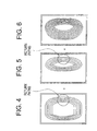
- Figure 4 depicts exemplary wire patterns for one quadrant of a main gradient coil 182, a corrector coil 184, and the equivalent effective coil. It will be evident from observation of these figures the methodology for formation of the main gradient coil 182 and there from, the corrector coil 184. In Figure 4 the right most pattern depicts an exemplary wire pattern configured to provide a large field of view. From this effective coil design, a main gradient coil 182 may be ascertained by the process 220 to arrive at a coil configuration that provides a desired small field of view. Finally, the geometry of the necessary corrector coil 184 may be determined as identified in process 230.
- the wire patterns depicted in Figures 4, 5, and 6 correspond to the right half of a coil (iso-center in this example is to the left).
- the main gradient coil 182 winding has the return path pushed out to the right so that it overlaps with the corrector coil 184 return path. Therefore, the sum of the fields generated by the two windings produces a magnetic field identical to that from the "equivalent coil" show on the right.
- the system and methodology described in the numerous embodiments hereinbefore provides a system and method reducing power deposition in transverse gradient coils that facilitates MR imaging and avoiding peripheral nerve stimulation (PNST), and potentially increasing gradient slew rates for reduced overall imaging durations.
- the disclosed invention may be embodied in the form of computer-implemented processes and apparatuses for practicing those processes.
- the present invention can also be embodied in the form of computer program code containing instructions embodied in tangible media, such as floppy diskettes, CD-ROMs, hard drives, or any other computer-readable storage medium such as 111 and 112, wherein, when the computer program code is loaded into and executed by a computer, the computer becomes an apparatus for practicing the invention.
- the present invention can also be embodied in the form of computer program code, for example, whether stored in a storage medium 111, 112, loaded into and/or executed by a computer, or as data signal 110 transmitted whether a modulated carrier wave or not, over some transmission medium, such as over electrical wiring or cabling, through fiber optics, or via electromagnetic radiation, wherein, when the computer program code is loaded into and executed by a computer, the computer becomes an apparatus for practicing the invention.
- the computer program code segments configure the microprocessor to create specific logic circuits.
Landscapes
- Physics & Mathematics (AREA)
- Condensed Matter Physics & Semiconductors (AREA)
- General Physics & Mathematics (AREA)
- Magnetic Resonance Imaging Apparatus (AREA)
Applications Claiming Priority (2)
| Application Number | Priority Date | Filing Date | Title |
|---|---|---|---|
| US10/065,417 US6680612B1 (en) | 2002-10-16 | 2002-10-16 | Gradient coil apparatus for magnetic resonance imaging |
| US65417 | 2002-10-16 |
Publications (3)
| Publication Number | Publication Date |
|---|---|
| EP1411367A2 true EP1411367A2 (fr) | 2004-04-21 |
| EP1411367A3 EP1411367A3 (fr) | 2004-12-01 |
| EP1411367B1 EP1411367B1 (fr) | 2012-08-22 |
Family
ID=29998854
Family Applications (1)
| Application Number | Title | Priority Date | Filing Date |
|---|---|---|---|
| EP03256514A Expired - Lifetime EP1411367B1 (fr) | 2002-10-16 | 2003-10-15 | Bobine à gradient pour l'imagerie par résonance magnétique |
Country Status (3)
| Country | Link |
|---|---|
| US (1) | US6680612B1 (fr) |
| EP (1) | EP1411367B1 (fr) |
| JP (1) | JP4718112B2 (fr) |
Cited By (1)
| Publication number | Priority date | Publication date | Assignee | Title |
|---|---|---|---|---|
| GB2408582B (en) * | 2003-11-20 | 2006-11-29 | Ge Med Sys Global Tech Co Llc | MRI system utilizing supplemental static field-shaping coils |
Families Citing this family (9)
| Publication number | Priority date | Publication date | Assignee | Title |
|---|---|---|---|---|
| US20040075434A1 (en) * | 2002-10-16 | 2004-04-22 | Vavrek Robert Michael | Gradient coil apparatus for magnetic resonance imaging |
| WO2005043183A1 (fr) * | 2003-10-30 | 2005-05-12 | Koninklijke Philips Electronics, N.V. | Systeme d'imagerie par resonance magnetique equipe d'un aimant a angle de champ variable |
| WO2005050235A1 (fr) * | 2003-11-24 | 2005-06-02 | The University Of Queensland | Bobines de gradient presentant une forme libre pour irm |
| US6975116B2 (en) * | 2003-11-26 | 2005-12-13 | Ge Medical Systems Global Technology Company, Llc | Method and apparatus for multiple field of view gradient coils |
| US9513353B2 (en) * | 2008-05-08 | 2016-12-06 | The University Of Queensland | Arrangement of coils for MRI apparatus |
| US7932722B2 (en) * | 2009-04-27 | 2011-04-26 | General Electric Company | Transversely folded gradient coil |
| US9182465B2 (en) * | 2011-03-04 | 2015-11-10 | Siemens Aktiengesellschaft | MRT gradient system with integrated main magnetic field generation |
| WO2016016356A1 (fr) * | 2014-07-30 | 2016-02-04 | Koninklijke Philips N.V. | Système d'amplificateur de gradient pour attaquer une bobine de gradient et procédé de configuration |
| WO2020198460A1 (fr) * | 2019-03-27 | 2020-10-01 | The General Hospital Corporation | Procédé de conception de bobines électromagnétiques présentant une contrainte de stimulation nerveuse périphérique explicite en fonction d'une pénalité oracle |
Family Cites Families (4)
| Publication number | Priority date | Publication date | Assignee | Title |
|---|---|---|---|---|
| US5311135A (en) | 1992-12-11 | 1994-05-10 | General Electric Company | Multiple tap gradient field coil for magnetic resonance imaging |
| GB2295020B (en) * | 1994-11-03 | 1999-05-19 | Elscint Ltd | Modular whole - body gradient coil |
| DE19937065C1 (de) * | 1999-08-05 | 2001-03-08 | Siemens Ag | Vorrichtung und Verfahren zur Stimulationsunterdrückung bei Magnetresonanztomographiegeräten |
| US6538443B2 (en) | 2001-03-20 | 2003-03-25 | Koninklijke Philips Electronics N.V. | MRI gradient coil with variable field of view and apparatus and methods employing the same |
-
2002
- 2002-10-16 US US10/065,417 patent/US6680612B1/en not_active Expired - Lifetime
-
2003
- 2003-10-15 JP JP2003354464A patent/JP4718112B2/ja not_active Expired - Lifetime
- 2003-10-15 EP EP03256514A patent/EP1411367B1/fr not_active Expired - Lifetime
Non-Patent Citations (1)
| Title |
|---|
| HARVEY P.R. ET AL., MRM, vol. 42, 1999, pages 561 - 570 |
Cited By (1)
| Publication number | Priority date | Publication date | Assignee | Title |
|---|---|---|---|---|
| GB2408582B (en) * | 2003-11-20 | 2006-11-29 | Ge Med Sys Global Tech Co Llc | MRI system utilizing supplemental static field-shaping coils |
Also Published As
| Publication number | Publication date |
|---|---|
| JP4718112B2 (ja) | 2011-07-06 |
| JP2004136091A (ja) | 2004-05-13 |
| US6680612B1 (en) | 2004-01-20 |
| EP1411367B1 (fr) | 2012-08-22 |
| EP1411367A3 (fr) | 2004-12-01 |
Similar Documents
| Publication | Publication Date | Title |
|---|---|---|
| US6479999B1 (en) | Efficiently shielded MRI gradient coil with discretely or continuously variable field of view | |
| EP1357391B1 (fr) | Ensemble de bobines de gradient pouvant produire un champ de vision variable | |
| US7221161B2 (en) | Coil arrays for parallel imaging in magnetic resonance imaging | |
| US20100060282A1 (en) | Three-dimensional asymmetric transverse gradient coils | |
| JP4067381B2 (ja) | 極めて高磁場の磁気共鳴イメージングで使用するために電場曝露を低減させたrfコイル | |
| US20080272784A1 (en) | Magnetic Resonance Imaging Device and Method for Operating a Magnetic Resonance Imaging Device | |
| US6940282B2 (en) | Switchable transmit array coil | |
| US6680612B1 (en) | Gradient coil apparatus for magnetic resonance imaging | |
| EP0690312B1 (fr) | Bobines à gradient asymétriques pour l'imagerie par résonance magnétique | |
| US6882153B2 (en) | Gradient coil apparatus for magnetic resonance imaging | |
| US6822451B2 (en) | Non-coupling magnetic sheilding coil | |
| US6487436B1 (en) | Switchable field of view apparatus and method for magnetic resonance imaging | |
| US6313630B1 (en) | Modular gradient system for MRI system | |
| US7047062B2 (en) | Magnetic resonance imaging with nested gradient pulses | |
| US6538442B2 (en) | MRI system having RF shielding gradient coil structure | |
| CN108027410A (zh) | 用于磁共振图像引导的治疗的射频天线组件 | |
| US6466017B1 (en) | MRI system with modular gradient system | |
| US6717409B2 (en) | Method for calculating conductor paths in a switched gradient coil system, and magnetic resonance tomography apparatus employing such a switched gradient coil system | |
| US6975116B2 (en) | Method and apparatus for multiple field of view gradient coils | |
| US12455331B2 (en) | Uniform field generating coil cooling configuration and lead routing | |
| US7019525B2 (en) | Method and apparatus for magnetic resonance imaging | |
| Prost et al. | How does an MR scanner operate? | |
| JPH0549608A (ja) | 磁気共鳴映像装置 |
Legal Events
| Date | Code | Title | Description |
|---|---|---|---|
| PUAI | Public reference made under article 153(3) epc to a published international application that has entered the european phase |
Free format text: ORIGINAL CODE: 0009012 |
|
| AK | Designated contracting states |
Kind code of ref document: A2 Designated state(s): AT BE BG CH CY CZ DE DK EE ES FI FR GB GR HU IE IT LI LU MC NL PT RO SE SI SK TR |
|
| AX | Request for extension of the european patent |
Extension state: AL LT LV MK |
|
| PUAL | Search report despatched |
Free format text: ORIGINAL CODE: 0009013 |
|
| AK | Designated contracting states |
Kind code of ref document: A3 Designated state(s): AT BE BG CH CY CZ DE DK EE ES FI FR GB GR HU IE IT LI LU MC NL PT RO SE SI SK TR |
|
| AX | Request for extension of the european patent |
Extension state: AL LT LV MK |
|
| 17P | Request for examination filed |
Effective date: 20050601 |
|
| AKX | Designation fees paid |
Designated state(s): DE NL |
|
| 17Q | First examination report despatched |
Effective date: 20090918 |
|
| GRAP | Despatch of communication of intention to grant a patent |
Free format text: ORIGINAL CODE: EPIDOSNIGR1 |
|
| GRAS | Grant fee paid |
Free format text: ORIGINAL CODE: EPIDOSNIGR3 |
|
| GRAA | (expected) grant |
Free format text: ORIGINAL CODE: 0009210 |
|
| AK | Designated contracting states |
Kind code of ref document: B1 Designated state(s): DE NL |
|
| REG | Reference to a national code |
Ref country code: DE Ref legal event code: R096 Ref document number: 60341879 Country of ref document: DE Effective date: 20121018 |
|
| REG | Reference to a national code |
Ref country code: NL Ref legal event code: T3 |
|
| PLBE | No opposition filed within time limit |
Free format text: ORIGINAL CODE: 0009261 |
|
| STAA | Information on the status of an ep patent application or granted ep patent |
Free format text: STATUS: NO OPPOSITION FILED WITHIN TIME LIMIT |
|
| 26N | No opposition filed |
Effective date: 20130523 |
|
| REG | Reference to a national code |
Ref country code: DE Ref legal event code: R097 Ref document number: 60341879 Country of ref document: DE Effective date: 20130523 |
|
| PGFP | Annual fee paid to national office [announced via postgrant information from national office to epo] |
Ref country code: NL Payment date: 20131026 Year of fee payment: 11 |
|
| REG | Reference to a national code |
Ref country code: NL Ref legal event code: V1 Effective date: 20150501 |
|
| PG25 | Lapsed in a contracting state [announced via postgrant information from national office to epo] |
Ref country code: NL Free format text: LAPSE BECAUSE OF NON-PAYMENT OF DUE FEES Effective date: 20150501 |
|
| PGFP | Annual fee paid to national office [announced via postgrant information from national office to epo] |
Ref country code: DE Payment date: 20200917 Year of fee payment: 18 |
|
| REG | Reference to a national code |
Ref country code: DE Ref legal event code: R119 Ref document number: 60341879 Country of ref document: DE |
|
| PG25 | Lapsed in a contracting state [announced via postgrant information from national office to epo] |
Ref country code: DE Free format text: LAPSE BECAUSE OF NON-PAYMENT OF DUE FEES Effective date: 20220503 |