EP1413049B1 - Oszillator - Google Patents
Oszillator Download PDFInfo
- Publication number
- EP1413049B1 EP1413049B1 EP02741582A EP02741582A EP1413049B1 EP 1413049 B1 EP1413049 B1 EP 1413049B1 EP 02741582 A EP02741582 A EP 02741582A EP 02741582 A EP02741582 A EP 02741582A EP 1413049 B1 EP1413049 B1 EP 1413049B1
- Authority
- EP
- European Patent Office
- Prior art keywords
- fundamental frequency
- oscillator
- differential
- ground
- frequency
- Prior art date
- Legal status (The legal status is an assumption and is not a legal conclusion. Google has not performed a legal analysis and makes no representation as to the accuracy of the status listed.)
- Expired - Lifetime
Links
- 238000010168 coupling process Methods 0.000 claims abstract description 66
- 238000005859 coupling reaction Methods 0.000 claims abstract description 66
- 230000008878 coupling Effects 0.000 claims abstract description 64
- 238000000034 method Methods 0.000 claims abstract description 9
- 239000003990 capacitor Substances 0.000 description 35
- 238000010586 diagram Methods 0.000 description 4
- 230000001965 increasing effect Effects 0.000 description 3
- 239000004065 semiconductor Substances 0.000 description 2
- 230000006978 adaptation Effects 0.000 description 1
- 230000000903 blocking effect Effects 0.000 description 1
- 230000001413 cellular effect Effects 0.000 description 1
- 230000008094 contradictory effect Effects 0.000 description 1
- 230000001939 inductive effect Effects 0.000 description 1
- 238000004519 manufacturing process Methods 0.000 description 1
- 238000001228 spectrum Methods 0.000 description 1
Images




Classifications
-
- H—ELECTRICITY
- H03—ELECTRONIC CIRCUITRY
- H03B—GENERATION OF OSCILLATIONS, DIRECTLY OR BY FREQUENCY-CHANGING, BY CIRCUITS EMPLOYING ACTIVE ELEMENTS WHICH OPERATE IN A NON-SWITCHING MANNER; GENERATION OF NOISE BY SUCH CIRCUITS
- H03B5/00—Generation of oscillations using amplifier with regenerative feedback from output to input
- H03B5/08—Generation of oscillations using amplifier with regenerative feedback from output to input with frequency-determining element comprising lumped inductance and capacitance
- H03B5/12—Generation of oscillations using amplifier with regenerative feedback from output to input with frequency-determining element comprising lumped inductance and capacitance active element in amplifier being semiconductor device
-
- H—ELECTRICITY
- H03—ELECTRONIC CIRCUITRY
- H03B—GENERATION OF OSCILLATIONS, DIRECTLY OR BY FREQUENCY-CHANGING, BY CIRCUITS EMPLOYING ACTIVE ELEMENTS WHICH OPERATE IN A NON-SWITCHING MANNER; GENERATION OF NOISE BY SUCH CIRCUITS
- H03B5/00—Generation of oscillations using amplifier with regenerative feedback from output to input
- H03B5/08—Generation of oscillations using amplifier with regenerative feedback from output to input with frequency-determining element comprising lumped inductance and capacitance
- H03B5/12—Generation of oscillations using amplifier with regenerative feedback from output to input with frequency-determining element comprising lumped inductance and capacitance active element in amplifier being semiconductor device
- H03B5/1206—Generation of oscillations using amplifier with regenerative feedback from output to input with frequency-determining element comprising lumped inductance and capacitance active element in amplifier being semiconductor device using multiple transistors for amplification
- H03B5/1212—Generation of oscillations using amplifier with regenerative feedback from output to input with frequency-determining element comprising lumped inductance and capacitance active element in amplifier being semiconductor device using multiple transistors for amplification the amplifier comprising a pair of transistors, wherein an output terminal of each being connected to an input terminal of the other, e.g. a cross coupled pair
-
- H—ELECTRICITY
- H03—ELECTRONIC CIRCUITRY
- H03B—GENERATION OF OSCILLATIONS, DIRECTLY OR BY FREQUENCY-CHANGING, BY CIRCUITS EMPLOYING ACTIVE ELEMENTS WHICH OPERATE IN A NON-SWITCHING MANNER; GENERATION OF NOISE BY SUCH CIRCUITS
- H03B27/00—Generation of oscillations providing a plurality of outputs of the same frequency but differing in phase, other than merely two anti-phase outputs
-
- H—ELECTRICITY
- H03—ELECTRONIC CIRCUITRY
- H03B—GENERATION OF OSCILLATIONS, DIRECTLY OR BY FREQUENCY-CHANGING, BY CIRCUITS EMPLOYING ACTIVE ELEMENTS WHICH OPERATE IN A NON-SWITCHING MANNER; GENERATION OF NOISE BY SUCH CIRCUITS
- H03B5/00—Generation of oscillations using amplifier with regenerative feedback from output to input
- H03B5/08—Generation of oscillations using amplifier with regenerative feedback from output to input with frequency-determining element comprising lumped inductance and capacitance
- H03B5/12—Generation of oscillations using amplifier with regenerative feedback from output to input with frequency-determining element comprising lumped inductance and capacitance active element in amplifier being semiconductor device
- H03B5/1231—Generation of oscillations using amplifier with regenerative feedback from output to input with frequency-determining element comprising lumped inductance and capacitance active element in amplifier being semiconductor device the amplifier comprising one or more bipolar transistors
Definitions
- the invention concerns oscillators and is more particularly directed to the locking of two or more differential oscillators together.
- Oscillators are used in most types of electronic circuitry. In some applications the frequency accuracy and stability are of a lesser importance, in other applications it is extremely important that an oscillator has a pure frequency spectrum with a very low phase noise.
- One type of application where these demands are set very high is in communication systems.
- Oscillators in communication systems are often considered as building blocks that ought to be small, preferably integrated, have a low manufacturing cost, be reliable, have a low power consumption and also fulfill among the most strict signal quality requirements.
- four orthogonal phases (quadrature) of the oscillator signal are required requiring further power and space consuming circuitry. Obtaining these characteristics is a difficult task, especially if the oscillator building block is to be realized on an integrated circuit with a limited semiconductor area available and a limited available power, without any external components.
- a 1.8GHz CMOS Quadrature Voltage-Controlled Oscillator (VCO) Using the Constant-Current LC Ring Oscillator Structure IEEE, US, vol. 4, 31 May 1998, pp 378-381, by Chung-Yu Wu et al., and EP-A-0 989 668 show oscillator circuits with first and second differential oscillators each with a fundamental AC-ground point, and which have substantially the same fundamental frequencies.
- An object of the invention is to define an improved method of frequency locking a first differential oscillator to a second differential oscillator.
- a further object of the invention is to define an oscillator circuit having the features of the first part of claim 1 which is improved and which has a low phase noise.
- the first differential oscillator and the second differential oscillator are substantially identical.
- the first AC coupling is between a first fundamental frequency AC-ground point of the first differential oscillator and a first fundamental frequency AC-ground point of the second differential oscillator, the first fundamental frequency AC-ground points being identical fundamental frequency AC-ground points.
- the oscillator circuit comprises four fundamental frequency outputs, the four outputs being in quadrature.
- the oscillator circuit comprises a second AC coupling element between a second fundamental frequency AC-ground point of the first differential oscillator and a second fundamental frequency AC-ground point of the second differential oscillator, the second fundamental frequency AC-ground points being identical fundamental frequency AC-ground points.
- the oscillator circuit can comprise a second quadruple frequency output, the second quadruple frequency output being coupled to the second AC coupling, the first and second quadruple frequency outputs being differential.
- the oscillator circuit comprises a third differential oscillator having at least a first fundamental frequency AC-ground point.
- the first AC coupling is further AC coupled to the first fundamental frequency AC-ground point of the third differential oscillator, or the oscillator circuit comprises a second AC coupling between a second fundamental frequency AC-ground point of the first differential oscillator and a second fundamental frequency AC-ground point of the third differential oscillator, the second fundamental frequency AC-ground points being identical fundamental frequency AC-ground points and separate from the first fundamental frequency AC-ground points.
- the third differential oscillator has substantially a same fundamental frequency as the first and second differential oscillators.
- the oscillator circuit comprises a fourth differential oscillator having at least a first fundamental frequency AC-ground point.
- the first AC coupling element is further AC coupled to the first fundamental frequency AC-ground point of the fourth differential oscillator, or the oscillator circuit further comprises a third AC coupling between a fundamental frequency AC-ground point of the second differential oscillator being separate from the first fundamental frequency AC-ground point and a corresponding fundamental frequency AC-ground point of the fourth differential oscillator.
- the fourth differential oscillator has a fundamental frequency which is substantially the frequency of the fundamental frequency of the first and second differential oscillator.
- one AC coupling between two fundamental frequency AC-ground points is further coupled to either a voltage source via an AC-impedance element, or to ground via an AC-impedance element.
- one AC coupling between two fundamental frequency AC-ground points is either a direct coupling, a resistive coupling, or a capacitive coupling.
- a communication unit the communication unit comprises an oscillator circuit according to any one of the above described embodiments.
- a primary purpose of the invention is to provide an improved differential oscillator with a high quality signal output in quadrature. This is obtained according to the invention by AC coupling fundamental frequency AC-ground points of differential oscillators to frequency lock them together. By locking two or more differential oscillators together according to the invention the phase noise of each oscillator is reduced by up to 3n dB, where 2 n is the number of coupled oscillators. Further, a pair of differential oscillators lock in such a way that the output of the two oscillators are in quadrature. Still further, the major remnant frequency component at the coupling point between two connected differential oscillators is four times the fundamental frequency, thereby providing frequency multiplication.
- Quadrature output is attained and the phase noise can be reduced by 3 dB by coupling two differential oscillators together according to the invention, without occupying more space or consuming any extra power for the coupling.
- Figure 1 shows an example of a differential LC oscillator.
- the differential LC oscillator comprises a resonance circuit with a capacitor part C3, C4 and an inductor part L1, L2.
- the LC oscillator of this example is of a parallel resonance type.
- the differential LC oscillator further comprises a drive part with transistors T1, T2 resistors R1, R2, R3 and capacitors C1, C2.
- f o 1/(2 ⁇ (L ⁇ C) 1 ⁇ 2 )
- L is the inductance of the resonator
- C the capacitance of the resonator.
- the impedance of the resonance circuit is high, on the other hand if it was a serial resonance LC oscillator, then resonance would occur when the serial resonance circuit has a low impedance.
- the capacitor part C3, C4, of the resonator is illustrated as divided into two capacitors C3 and C4.
- the inductor L1, L2 of the resonator is also illustrated as divided into two inductors L1 and L2, this can also be viewed as a single center tapped inductor.
- the capacitor part C3, C4, of the resonator is divided into two capacitors to create a fundamental frequency AC-ground point 140.
- the inductor L1, L2 of the resonator is divided into two inductors L1, L2 to thereby create a for this example necessary DC biasing point 150 which also acts as a fundamental frequency AC-ground point.
- the differential LC oscillator further comprises one fundamental frequency AC-ground point 130 and two combined fundamental frequency AC-ground and DC biasing points 110, 120.
- a fundamental frequency AC-ground point is a point where the fundamental frequency of a differential oscillator is effectively cancelled due to the symmetry of the differential oscillator.
- a fundamental frequency AC-ground further comprises only odd harmonics, i.e. even multiples of the fundamental frequency, the first harmonic usually being the dominant one.
- the invention is based on the basic inventive idea of AC coupling one fundamental frequency AC point of one differential oscillator to one fundamental frequency AC point of another differential oscillator to thereby let the two differential oscillators strive to cancel out the dominant harmonic at the AC coupled fundamental frequency AC-ground points.
- the reason that the differential oscillators will strive to cancel out the dominant harmonic is that the AC coupled points are AC-ground points.
- the differential oscillators will therefore be 90° out of phase (to be able to cancel the dominant harmonic), i.e. in quadrature, and of the same frequency.
- Each differential oscillator provides 0° and 180°, these will be 90° apart, thus providing 0°, 90°, 180°, and 270° from two coupled differential oscillators, which phases are very useful in different types of equipment, especially communication equipment.
- the dominant frequency that is left at the coupling point will be four times the fundamental frequency of the differential oscillators, unless there is a weak AC coupling in which case the double frequency can be the dominant one.
- This frequency can be tapped and used, thus in a simple way frequency multiplying.
- the frequency difference between two, or more, differential oscillators of the same frequency that are to be frequency locked according to the invention should preferably only differ in frequency in the order of 10% or less.
- the invention is not restricted to the use of a parallel or a serial resonance LC oscillator, nor to fixed frequency or tunable oscillators, the only restriction the invention puts on the oscillators used is that they both have to have at least one fundamental frequency AC-ground point each.
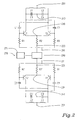
- FIG. 2 shows a schematic of two differential oscillators coupled together according to one basic embodiment according to the invention.
- Each differential LC oscillator comprises a resonance circuit part with a respective capacitor part C3, C4, C3', C4' and a respective inductor part L1, L2, L1', L2'.
- Each differential LC oscillator further comprises a drive part with transistors T1, T1', T2, T2', resistors R1, R1', R2, R2', R3, R3' and capacitors C1, C1', C2, C2'.
- Each differential oscillator comprises a first 210, 211, a second 220, 221, a third 230, 231, a fourth 240, 241, and a fifth 250, 251 fundamental frequency AC-ground point.
- This basic example couples the second fundamental frequency AC-points 220, 221 with each other via an AC coupling element 290.
- the AC coupling element 290 can be capacitive, resistive, direct coupled, or the like. If there is a weak AC coupling, then the first harmonic might not be cancelled completely.
- the fundamental frequency AC-ground points of the differential oscillators that are coupled together are preferably the same type of point so that the coupled points have the same amplitude. Otherwise some sort of matching might be needed in the coupling.
- the second fundamental frequency AC-points 220, 221 are also DC biasing points of the differential oscillators, these points are also coupled to a DC biasing point 270 via a DC coupling element 271.
- the DC coupling element can suitably be resistive, inductive or direct coupled.
- the differential oscillators When the differential oscillators have frequency locked, then ideally the first harmonic (2f o ) will have been completely cancelled at the fundamental frequency AC-ground points that are AC coupled. The other fundamental frequency AC-ground points will still have the first harmonic present, and they will be differential between the two differential oscillators.
- the third fundamental frequency AC-ground points 230, 231 can be as 2f o differential outputs.
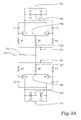
- FIGS 3A to 3C show suitable embodiments of locked differential oscillators according to the invention.
- Each differential LC oscillator comprises a resonance circuit part with a respective capacitor part C3, C4, C3', C4' and a respective inductor part L1, L2, L1', L2'.
- Each differential LC oscillator further comprises a drive part with transistors T1, T1', T2, T2', resistors R1, R1', R2, R2', R3, R3' and capacitors C1, C1', C2, C2'.
- each differential oscillator comprises a first 310, 311, a second 320, 321, a third 330, 331, a fourth 340, 341, and a fifth 350, 351 fundamental frequency AC-ground point.
- Figure 3A shows how the second fundamental frequency AC-ground points 320, 321 are directly coupled together. These fundamental frequency AC-ground points 320, 321 are also DC biasing points of the differential oscillators. Therefore a DC biasing 370 is needed, which is suitably connected to the fundamental frequency AC-ground points 320, 321 by means of an inductor 373, which is a good DC coupling but AC blocking element.
- Figure 3B shows how the third fundamental frequency AC-ground points 330, 331 are coupled together via an AC coupling element, a capacitor 393.
- These fundamental frequency AC-ground points 330, 331 are not DC biasing points of the differential oscillators. Therefore, DC biasing is not needed here.
- Figure 3C shows in this third example how the fourth fundamental frequency AC-ground points 340, 341 are directly coupled together. These fundamental frequency AC-ground points 340, 341 do not require any DC biasing either.
- the fourth fundamental frequency AC-ground points 340, 341 were created by splitting the capacitor of the resonator into two capacitors C3, C3', C4, C4'. The two capacitors are suitably of an equal size.
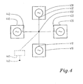
- Figure 4 shows an example of four differential oscillators 410, 420, 430, 440 locked together according to the invention in a star configuration, i.e. a fundamental frequency AC-ground point 412, 422, 432, 442 of each differential oscillator 410, 420, 430, 440 is AC coupled together 450.
- a fundamental frequency AC-ground point 412, 422, 432, 442 of each differential oscillator 410, 420, 430, 440 is AC coupled together 450.
- a DC biasing impedance 460 might be needed as well as a DC-biasing point 462.
- More or fewer differential oscillators can be frequency locked together in a star configuration such as this.
- a differential oscillator can use a same fundamental frequency AC-ground point for AC-coupling to two or more other differential oscillators.
- Figure 5 shows an example of four differential oscillators 510, 520, 530, 540 frequency locked together according to the invention in a serial configuration, i.e. any differential oscillator 510, 520, 530, 540 is not AC coupled together with more than two other differential oscillators 510, 520, 530, 540 by means of the fundamental frequency AC-ground points 512, 514, 522, 524, 532, 534, 542, 544.
- a second fundamental frequency AC-ground point 514 of the first differential oscillator 510 is AC coupled 551 together with a second fundamental frequency AC-ground point 524 of the second differential oscillator 520.
- differential oscillators having the same frequency should preferably only differ in frequency in the order of 10% or less.
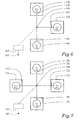
- FIGS 6 and 7 show particular configurations which, however, do not form part of the present invention.
- Figure 6 shows a first example of multiple frequency locking in a star configuration.
- Two differential oscillators 610, 630, with corresponding fundamental frequency AC-ground points 612, 632 have a fundamental frequency of f o .
- the first harmonic (2f o ) is cancelled at the common point 650, and the remaining dominant frequency at this point 650 is four times (4f o ) the fundamental frequency.
- a differential oscillator 620 that oscillates at twice (2f o ) the frequency of the other differential oscillators 610, 630, will have a dominant frequency at its fundamental frequency AC-ground point 622 which is four times (4f o ) the fundamental frequency of the other differential oscillators 610, 630.
- the dominant quadruple frequencies (4f o ) of the fundamental frequency AC-ground points will cancel, adjusting the phases differential oscillators 610, 620, 630 in the process.
- the dominating frequency at the coupling point will then be eight times (8f o ) the fundamental frequency (f o ), which is an efficient frequency multiplier that can be used.
- Figure 7 shows a second example of multiple frequency locking in a star configuration.
- this example also comprises two differential oscillators 710, 730 with a basic (f o ) fundamental frequency, and one differential oscillator 720 with a double fundamental frequency (2f o ).
- a fourth differential oscillator 740 with a quadruple fundamental frequency (4f o ) is also frequency locked. All of the differential oscillators comprise their corresponding fundamental frequency AC-ground point 712, 722, 732, 742, which are AC coupled together in a single point 750.
- a quadruple frequency (4f o ) differential oscillator 740 will have a dominating frequency at its fundamental frequency AC-ground points 742 that is eight times (8f o ) the basic frequency (f o ). This will cancel with the dominating frequency from the other three differential oscillators 710, 720, 730, leaving a dominating frequency of sixteen times (16f o ) the basic frequency (f o ) at the coupling point 750. This frequency can of course be used, if desired. Illustrated is a DC biasing impedance 760 as well as a DC-biasing point 762 that might be needed if the fundamental frequency AC-ground points used are of the DC biasing type as well.
- Oscillators according to the invention as building blocks in communication systems are preferably realized on an integrated circuit and preferably without any external components.
- the basic principle of the invention is to frequency lock differential oscillators to each other by AC coupling fundamental frequency AC-ground points of the differential oscillators with each other. This will lower the phase noise, provide quadrature phase outputs, and provide frequency multiplication, without increasing power consumption by any active coupling arrangements.
Landscapes
- Inductance-Capacitance Distribution Constants And Capacitance-Resistance Oscillators (AREA)
- Stabilization Of Oscillater, Synchronisation, Frequency Synthesizers (AREA)
- Surgical Instruments (AREA)
Claims (21)
- Oszillatorschaltung, die einen ersten differentiellen Oszillator und einen zweiten differentiellen Oszillator umfasst, wobei der erste differentielle Oszillator mindestens einen Grundfrequenz-AC-Erdungspunkt (210, 220, 230, 240, 250; 310, 320, 330, 340, 350) umfasst, und wobei der zweite differentielle Oszillator mindestens einen Grundfrequenz-AC-Erdungspunkt (211, 221, 231, 241, 251; 311, 321, 331, 341, 351) umfasst, und wobei der erste differentielle Oszillator und der zweite differentielle Oszillator im Wesentlichen die gleiche Grundfrequenz haben, wobei die Oszillatorschaltung ein erstes AC-Kopplungselement (290; 393; 450; 551; 650; 750) zwischen einem der mindestens einen Grundfrequenz-AC-Erdungspunkten des ersten differentiellen Oszillators und einem der mindestens einen Grundfrequenz-AC-Erdungspunkten des zweiten differentiellen Oszillators umfasst, und wobei das AC-Kopplungselement (290; 393; 450; 551; 650; 750) ausgebildet ist, um den ersten differentiellen Oszillator frequenzeinzurasten zu dem zweiten differentiellen Oszillator,
dadurch gekennzeichnet, dass die Oszillatorschaltung einen ersten Vierfachfrequenzausgang umfasst, wobei die erste Vierfachfrequenz viermal die Grundfrequenz der differentiellen Oszillatoren ist und dadurch, dass der erste Vierfachfrequenzausgang zu dem ersten AC-Kopplungselement (290; 393; 450; 551; 650; 750) gekoppelt ist. - Oszillatorschaltung nach Anspruch 1, dadurch gekennzeichnet, dass der erste differentielle Oszillator und der zweite differentielle Oszillator im Wesentlichen identisch sind.
- Oszillatorschaltung nach Anspruch 2, dadurch gekennzeichnet, dass das erste AC-Kopplungselement zwischen einem ersten Grundfrequenz-AC-Erdungspunkt des ersten differentiellen Oszillators und einem ersten Grundfrequenz-AC-Erdungspunkt des zweiten differentiellen Oszillators ist, wobei die ersten Grundfrequenz-AC-Erdungspunkte identische Grundfrequenz-AC-Erdungspunkte sind.
- Oszillatorschaltung nach Anspruch 3, dadurch gekennzeichnet, dass die Oszillatorschaltung vier Grundfrequenzausgänge umfasst, wobei die vier Ausgänge in Quadratur sind.
- Oszillatorschaltung nach Anspruch 3 oder 4, dadurch gekennzeichnet, dass die Oszillatorschaltung ein zweites AC-Kopplungselement umfasst zwischen einem zweiten Grundfrequenz-AC-Erdungspunkt des ersten differentiellen Oszillators und einem zweiten Grundfrequenz-AC-Erdungspunkt des zweiten differentiellen Oszillators, wobei die zweiten Grundfrequenz-AC-Erdungspunkte identische Grundfrequenz-AC-Erdungspunkte sind.
- Oszillatorschaltung nach Anspruch 5, dadurch gekennzeichnet, dass die Oszillatorschaltung einen zweiten Vierfachfrequenzausgang umfasst, wo die Vierfachfrequenz viermal die Grundfrequenz der differentiellen Oszillatoren ist und dadurch, dass der zweite Vierfachfrequenzausgang zu dem zweiten AC-Kopplungselement gekoppelt ist, wobei der erste und zweite Vierfachfrequenzausgang differenziell sind.
- Oszillatorschaltung nach Anspruch 3, dadurch gekennzeichnet, dass die Oszillatorschaltung einen dritten differentiellen Oszillator umfasst, mit mindestens einem ersten Grundfrequenz-AC-Erdungspunkt.
- Oszillatorschaltung nach Anspruch 7, dadurch gekennzeichnet, dass das erste AC-Kopplungselement ferner AC-gekoppelt ist zu dem ersten Grundfrequenz-AC-Erdungspunkt des vierten differentiellen Oszillators.
- Oszillatorschaltung nach Anspruch 7, dadurch gekennzeichnet, dass die Oszillatorschaltung ein zweites AC-Kopplungselement umfasst zwischen einem zweiten Grundfrequenz-AC-Erdungspunkt des ersten differentiellen Oszillators und einem zweiten Grundfrequenz-AC-Erdungspunkt des dritten differentiellen Oszillators, wobei die zweiten Grundfrequenz-AC-Erdungspunkte identische Grundfrequenz-AC-Erdungspunkte sind und separat von den ersten Grundfrequenz-AC-Erdungspunkten sind.
- Oszillatorschaltung nach einem der Ansprüche 7 bis 9, dadurch gekennzeichnet, dass der dritte differentielle Oszillator im Wesentlichen eine gleiche Grundfrequenz hat wie der erste und zweite differentiell Oszillator.
- Oszillatorschaltung nach einem der Ansprüche 7 bis 10, dadurch gekennzeichnet, dass die Oszillatorschaltung einen vierten differentiellen Oszillator umfasst mit mindestens einem ersten Grundfrequenz-AC-Erdungspunkt.
- Oszillatorschaltung nach Anspruch 11, dadurch gekennzeichnet, dass das erste AC-Kopplungselement (450) ferner AC-gekoppelt ist zu dem ersten Grundfrequenz-AC-Erdungspunkt des dritten differentiellen Oszillators.
- Oszillatorschaltung nach Anspruch 11, dadurch gekennzeichnet, dass die Oszillatorschaltung ferner ein drittes AC-Kopplungselement (553) umfasst zwischen einem Grundfrequenz-AC-Erdungspunkt des zweiten differentiellen Oszillators, der separat von dem ersten Grundfrequenz-AC-Erdungspunkt ist, und einem entsprechenden Grundfrequenz-AC-Erdungspunkt des vierten differentiellen Oszillators.
- Oszillatorschaltung nach einem der Ansprüche 11 bis 13, dadurch gekennzeichnet, dass der vierte differentielle Oszillator eine Grundfrequenz hat, welche im Wesentlichen die Frequenz der Grundfrequenz des ersten und zweiten differentiellen Oszillators ist.
- Oszillatorschaltung nach einem der Ansprüche 1 bis 14, dadurch gekennzeichnet, dass ein AC-Kopplungselement zwischen zwei Grundfrequenz-AC-Erdungspunkten ferner zu einer Spannungsquelle über ein AC-Impedanzelement gekoppelt ist.
- Oszillatorschaltung nach einem der Ansprüche 1 bis 14, dadurch gekennzeichnet, dass ein AC-Kopplungselement zwischen zwei Grundfrequenz-AC-Erdungspunkten ferner zu Erde über ein AC-Impedanzelement gekoppelt ist.
- Oszillatorschaltung nach einem der Ansprüche 1 bis 16, dadurch gekennzeichnet, dass ein AC-Kopplungselement (290) zwischen zwei Grundfrequenz-AC-Erdungspunkten (320, 321; 340, 341) eine direkte Kopplung ist.
- Oszillatorschaltung nach einem der Ansprüche 1 bis 16, dadurch gekennzeichnet, dass ein AC-Kopplungselement (290) zwischen zwei Grundfrequenz-AC-Erdungspunkten eine resistive Kopplung ist.
- Oszillatorschaltung nach einem der Ansprüche 1 bis 16, dadurch gekennzeichnet, dass ein AC-Kopplungselement (290; 393) zwischen zwei Grundfrequenz-AC-Erdungspunkten eine kapazitive Kopplung ist.
- Kommunikationseinheit, dadurch gekennzeichnet, dass die Kommunikationseinheit eine Oszillatorschaltung nach einem der Ansprüche 1 bis 19 umfasst.
- Verfahren des Frequenzeinrastens eines ersten differentiellen Oszillators zu einem zweiten differentiellen Oszillator, wobei der erste differentielle Oszillator mindestens einen Grundfrequenz-AC-Erdungspunkt (210, 220, 230, 240, 250; 310, 320, 330, 340, 350) umfasst, der zweite differentiell Oszillator mindestens einen Grundfrequenz-AC-Erdungspunkt (211, 222, 231, 241, 251; 311, 321, 331, 341, 351) umfasst, das Verfahren umfassend:Bereitstellen des ersten differentiellen Oszillators und des zweiten differentiellen Oszillators, die im Wesentlichen die gleichen Grundfrequenzen haben, Koppeln, unter Verwendung eines Kopplungselements, eines Grundfrequenz-AC-Erdungspunkts des ersten differentiellen Oszillators mit einem Grundfrequenz-AC-Erdungspunkt des zweiten differentiellen Oszillators, wobei das Kopplungselement den ersten differentiellen Oszillator zu dem zweiten differentiellen Oszillator frequenzeinrastet, dadurch gekennzeichnet, dass das Verfahren ferner umfasst:Bereitstellen eines ersten Vierfachfrequenzausgangs, der zu dem AC-Kopplungselement gekoppelt ist, wobei die Vierfachfrequenz viermal die Grundfrequenz der differentiellen Oszillatoren ist.
Applications Claiming Priority (3)
| Application Number | Priority Date | Filing Date | Title |
|---|---|---|---|
| SE0102421 | 2001-07-05 | ||
| SE0102421A SE0102421D0 (sv) | 2001-07-05 | 2001-07-05 | Oscillator |
| PCT/SE2002/001209 WO2003005560A1 (en) | 2001-07-05 | 2002-06-20 | Oscillator |
Publications (2)
| Publication Number | Publication Date |
|---|---|
| EP1413049A1 EP1413049A1 (de) | 2004-04-28 |
| EP1413049B1 true EP1413049B1 (de) | 2010-08-04 |
Family
ID=20284760
Family Applications (1)
| Application Number | Title | Priority Date | Filing Date |
|---|---|---|---|
| EP02741582A Expired - Lifetime EP1413049B1 (de) | 2001-07-05 | 2002-06-20 | Oszillator |
Country Status (10)
| Country | Link |
|---|---|
| US (1) | US6903614B2 (de) |
| EP (1) | EP1413049B1 (de) |
| JP (1) | JP2004534468A (de) |
| KR (1) | KR100933379B1 (de) |
| CN (1) | CN100361385C (de) |
| AT (1) | ATE476785T1 (de) |
| DE (1) | DE60237210D1 (de) |
| ES (1) | ES2349140T3 (de) |
| SE (1) | SE0102421D0 (de) |
| WO (1) | WO2003005560A1 (de) |
Families Citing this family (12)
| Publication number | Priority date | Publication date | Assignee | Title |
|---|---|---|---|---|
| JP2004289339A (ja) * | 2003-03-20 | 2004-10-14 | Alps Electric Co Ltd | 多バンド発振器 |
| EP1797636A1 (de) * | 2004-09-30 | 2007-06-20 | Koninklijke Philips Electronics N.V. | Frequenzabstimmbare-oszillatoranordnung |
| JP3954059B2 (ja) * | 2004-10-21 | 2007-08-08 | シャープ株式会社 | 発振器、通信装置 |
| JP2008544619A (ja) * | 2005-06-13 | 2008-12-04 | エヌエックスピー ビー ヴィ | 高い直線性を有する直交発振器 |
| CN101305440B (zh) * | 2005-10-05 | 2013-04-24 | 艾利森电话股份有限公司 | 具有最小化相位噪声用的可调谐滤波器的振荡电路 |
| DE102006017188A1 (de) * | 2006-04-12 | 2007-10-18 | Atmel Duisburg Gmbh | Integrierte differenzielle Oszillatorschaltung |
| GB2442034A (en) * | 2006-09-21 | 2008-03-26 | Iti Scotland Ltd | Voltage-controlled oscillator |
| US7843276B2 (en) * | 2006-12-22 | 2010-11-30 | Industrial Technology Research Institute | Oscillator |
| EP2162982A4 (de) * | 2007-06-20 | 2012-06-20 | Ericsson Telefon Ab L M | Oszillatoranordnung |
| JP2010219769A (ja) * | 2009-03-16 | 2010-09-30 | Toshiba Corp | 発振回路及び、その発振回路を用いた無線機 |
| WO2012025791A1 (en) * | 2010-08-26 | 2012-03-01 | Freescale Semiconductor, Inc. | Push-push oscillator circuit |
| US9490747B1 (en) * | 2015-12-31 | 2016-11-08 | Texas Instruments Incorporated | Re-configurable single transformer quadrature voltage controlled oscillator |
Citations (1)
| Publication number | Priority date | Publication date | Assignee | Title |
|---|---|---|---|---|
| EP0989668A1 (de) * | 1998-09-22 | 2000-03-29 | Texas Instruments Incorporated | Oszillatoreinrichtung mit Quadraturausgängen |
Family Cites Families (11)
| Publication number | Priority date | Publication date | Assignee | Title |
|---|---|---|---|---|
| US5379457A (en) * | 1993-06-28 | 1995-01-03 | Hewlett-Packard Company | Low noise active mixer |
| KR0153379B1 (ko) * | 1995-09-26 | 1998-11-16 | 김광호 | 디지탈 무선통신시스템의 업/다운컨버터용 전압제어발진기 |
| EP0909018B1 (de) * | 1997-09-11 | 2002-01-02 | Infineon Technologies AG | Oszillator |
| US5912596A (en) | 1998-01-26 | 1999-06-15 | International Business Machines Corporation | Apparatus and method for frequency tuning an LC oscillator in a integrated clock circuit |
| US6008701A (en) * | 1998-03-02 | 1999-12-28 | Analog Devices,Inc. | Quadrature oscillator using inherent nonlinearities of impedance cells to limit amplitude |
| GB2338849B (en) * | 1998-06-24 | 2003-03-19 | Motorola Inc | Voltage controlled oscillator circuit |
| US6249190B1 (en) * | 1999-08-25 | 2001-06-19 | Conexant Systems, Inc. | Differential oscillator |
| US6687494B1 (en) * | 2000-06-30 | 2004-02-03 | International Business Machines Corporation | Low power radio telephone image reject mixer |
| US6456167B1 (en) * | 2000-07-13 | 2002-09-24 | Industrial Technology Research Institute | Quadrature oscillator |
| KR100423502B1 (ko) * | 2001-11-20 | 2004-03-18 | 삼성전자주식회사 | 엘씨공진기와 차동증폭기를 이용한 전압제어발진기 |
| US20040127172A1 (en) * | 2002-12-27 | 2004-07-01 | Agere Systems Inc. | Phase-error suppressor and a method of suppressing phase-error |
-
2001
- 2001-07-05 SE SE0102421A patent/SE0102421D0/xx unknown
-
2002
- 2002-06-20 ES ES02741582T patent/ES2349140T3/es not_active Expired - Lifetime
- 2002-06-20 KR KR1020037017131A patent/KR100933379B1/ko not_active Expired - Fee Related
- 2002-06-20 AT AT02741582T patent/ATE476785T1/de not_active IP Right Cessation
- 2002-06-20 DE DE60237210T patent/DE60237210D1/de not_active Expired - Lifetime
- 2002-06-20 JP JP2003511405A patent/JP2004534468A/ja active Pending
- 2002-06-20 CN CNB028134893A patent/CN100361385C/zh not_active Expired - Lifetime
- 2002-06-20 WO PCT/SE2002/001209 patent/WO2003005560A1/en not_active Ceased
- 2002-06-20 EP EP02741582A patent/EP1413049B1/de not_active Expired - Lifetime
-
2004
- 2004-01-05 US US10/751,104 patent/US6903614B2/en not_active Expired - Lifetime
Patent Citations (1)
| Publication number | Priority date | Publication date | Assignee | Title |
|---|---|---|---|---|
| EP0989668A1 (de) * | 1998-09-22 | 2000-03-29 | Texas Instruments Incorporated | Oszillatoreinrichtung mit Quadraturausgängen |
Non-Patent Citations (1)
| Title |
|---|
| CHUNG-YU WU ET AL: "A 1.8 GHz CMOS quadrature voltage-controlled oscillator (VCO) using the constant-current LC ring oscillator structure", IEEE, vol. 4, 31 May 1998 (1998-05-31), New York, NY, US, pages 378 - 381, XP010289535 * |
Also Published As
| Publication number | Publication date |
|---|---|
| CN100361385C (zh) | 2008-01-09 |
| WO2003005560A1 (en) | 2003-01-16 |
| SE0102421D0 (sv) | 2001-07-05 |
| US20040150484A1 (en) | 2004-08-05 |
| DE60237210D1 (de) | 2010-09-16 |
| US6903614B2 (en) | 2005-06-07 |
| ATE476785T1 (de) | 2010-08-15 |
| EP1413049A1 (de) | 2004-04-28 |
| KR100933379B1 (ko) | 2009-12-22 |
| KR20040014594A (ko) | 2004-02-14 |
| JP2004534468A (ja) | 2004-11-11 |
| ES2349140T3 (es) | 2010-12-28 |
| CN1524335A (zh) | 2004-08-25 |
Similar Documents
| Publication | Publication Date | Title |
|---|---|---|
| EP1425844B1 (de) | Oszillator | |
| US6867656B2 (en) | Self-dividing oscillators | |
| US6911870B2 (en) | Quadrature voltage controlled oscillator utilizing common-mode inductive coupling | |
| US11336229B2 (en) | Radio frequency oscillator | |
| US7298225B2 (en) | Signal modulated voltage controlled oscillator system | |
| CN1708896B (zh) | 环形几何振荡器 | |
| CN103095217A (zh) | 低相位噪声压控振荡器 | |
| US6903614B2 (en) | Oscillator having an AC-coupling between fundamental frequency ground points | |
| US11843351B2 (en) | Integrated circuit including resonant circuit | |
| KR100691281B1 (ko) | 쿼드러처 전압제어발진기 | |
| CN100525070C (zh) | 振荡器电路 | |
| JPH036107A (ja) | 電圧制御発振器 | |
| US6690244B2 (en) | Low phase-noise integrated voltage controlled oscillator | |
| KR102570537B1 (ko) | 주파수 체배기를 이용한 초고주파 신호 생성 장치 | |
| US20040124930A1 (en) | Voltage controlled varactor oscillator with sensitivity spread |
Legal Events
| Date | Code | Title | Description |
|---|---|---|---|
| PUAI | Public reference made under article 153(3) epc to a published international application that has entered the european phase |
Free format text: ORIGINAL CODE: 0009012 |
|
| 17P | Request for examination filed |
Effective date: 20031211 |
|
| AK | Designated contracting states |
Kind code of ref document: A1 Designated state(s): AT BE CH CY DE DK ES FI FR GB GR IE IT LI LU MC NL PT SE TR |
|
| AX | Request for extension of the european patent |
Extension state: AL LT LV MK RO SI |
|
| RAP1 | Party data changed (applicant data changed or rights of an application transferred) |
Owner name: TELEFONAKTIEBOLAGET LM ERICSSON (PUBL) |
|
| 17Q | First examination report despatched |
Effective date: 20080710 |
|
| GRAP | Despatch of communication of intention to grant a patent |
Free format text: ORIGINAL CODE: EPIDOSNIGR1 |
|
| GRAS | Grant fee paid |
Free format text: ORIGINAL CODE: EPIDOSNIGR3 |
|
| GRAA | (expected) grant |
Free format text: ORIGINAL CODE: 0009210 |
|
| AK | Designated contracting states |
Kind code of ref document: B1 Designated state(s): AT BE CH CY DE DK ES FI FR GB GR IE IT LI LU MC NL PT SE TR |
|
| REG | Reference to a national code |
Ref country code: GB Ref legal event code: FG4D |
|
| REG | Reference to a national code |
Ref country code: CH Ref legal event code: EP |
|
| REG | Reference to a national code |
Ref country code: IE Ref legal event code: FG4D |
|
| REF | Corresponds to: |
Ref document number: 60237210 Country of ref document: DE Date of ref document: 20100916 Kind code of ref document: P |
|
| REG | Reference to a national code |
Ref country code: NL Ref legal event code: VDEP Effective date: 20100804 |
|
| REG | Reference to a national code |
Ref country code: ES Ref legal event code: FG2A Effective date: 20101215 |
|
| PG25 | Lapsed in a contracting state [announced via postgrant information from national office to epo] |
Ref country code: FI Free format text: LAPSE BECAUSE OF FAILURE TO SUBMIT A TRANSLATION OF THE DESCRIPTION OR TO PAY THE FEE WITHIN THE PRESCRIBED TIME-LIMIT Effective date: 20100804 Ref country code: AT Free format text: LAPSE BECAUSE OF FAILURE TO SUBMIT A TRANSLATION OF THE DESCRIPTION OR TO PAY THE FEE WITHIN THE PRESCRIBED TIME-LIMIT Effective date: 20100804 Ref country code: NL Free format text: LAPSE BECAUSE OF FAILURE TO SUBMIT A TRANSLATION OF THE DESCRIPTION OR TO PAY THE FEE WITHIN THE PRESCRIBED TIME-LIMIT Effective date: 20100804 |
|
| PG25 | Lapsed in a contracting state [announced via postgrant information from national office to epo] |
Ref country code: PT Free format text: LAPSE BECAUSE OF FAILURE TO SUBMIT A TRANSLATION OF THE DESCRIPTION OR TO PAY THE FEE WITHIN THE PRESCRIBED TIME-LIMIT Effective date: 20101206 Ref country code: CY Free format text: LAPSE BECAUSE OF FAILURE TO SUBMIT A TRANSLATION OF THE DESCRIPTION OR TO PAY THE FEE WITHIN THE PRESCRIBED TIME-LIMIT Effective date: 20100804 |
|
| PG25 | Lapsed in a contracting state [announced via postgrant information from national office to epo] |
Ref country code: SE Free format text: LAPSE BECAUSE OF FAILURE TO SUBMIT A TRANSLATION OF THE DESCRIPTION OR TO PAY THE FEE WITHIN THE PRESCRIBED TIME-LIMIT Effective date: 20100804 Ref country code: BE Free format text: LAPSE BECAUSE OF FAILURE TO SUBMIT A TRANSLATION OF THE DESCRIPTION OR TO PAY THE FEE WITHIN THE PRESCRIBED TIME-LIMIT Effective date: 20100804 Ref country code: GR Free format text: LAPSE BECAUSE OF FAILURE TO SUBMIT A TRANSLATION OF THE DESCRIPTION OR TO PAY THE FEE WITHIN THE PRESCRIBED TIME-LIMIT Effective date: 20101105 |
|
| PG25 | Lapsed in a contracting state [announced via postgrant information from national office to epo] |
Ref country code: DK Free format text: LAPSE BECAUSE OF FAILURE TO SUBMIT A TRANSLATION OF THE DESCRIPTION OR TO PAY THE FEE WITHIN THE PRESCRIBED TIME-LIMIT Effective date: 20100804 |
|
| PG25 | Lapsed in a contracting state [announced via postgrant information from national office to epo] |
Ref country code: IT Free format text: LAPSE BECAUSE OF FAILURE TO SUBMIT A TRANSLATION OF THE DESCRIPTION OR TO PAY THE FEE WITHIN THE PRESCRIBED TIME-LIMIT Effective date: 20100804 |
|
| PLBE | No opposition filed within time limit |
Free format text: ORIGINAL CODE: 0009261 |
|
| STAA | Information on the status of an ep patent application or granted ep patent |
Free format text: STATUS: NO OPPOSITION FILED WITHIN TIME LIMIT |
|
| 26N | No opposition filed |
Effective date: 20110506 |
|
| REG | Reference to a national code |
Ref country code: DE Ref legal event code: R097 Ref document number: 60237210 Country of ref document: DE Effective date: 20110506 |
|
| REG | Reference to a national code |
Ref country code: CH Ref legal event code: PL |
|
| REG | Reference to a national code |
Ref country code: FR Ref legal event code: ST Effective date: 20120229 |
|
| REG | Reference to a national code |
Ref country code: IE Ref legal event code: MM4A |
|
| PG25 | Lapsed in a contracting state [announced via postgrant information from national office to epo] |
Ref country code: CH Free format text: LAPSE BECAUSE OF NON-PAYMENT OF DUE FEES Effective date: 20110630 Ref country code: IE Free format text: LAPSE BECAUSE OF NON-PAYMENT OF DUE FEES Effective date: 20110620 Ref country code: LI Free format text: LAPSE BECAUSE OF NON-PAYMENT OF DUE FEES Effective date: 20110630 Ref country code: FR Free format text: LAPSE BECAUSE OF NON-PAYMENT OF DUE FEES Effective date: 20110630 |
|
| PG25 | Lapsed in a contracting state [announced via postgrant information from national office to epo] |
Ref country code: MC Free format text: LAPSE BECAUSE OF NON-PAYMENT OF DUE FEES Effective date: 20110630 |
|
| PG25 | Lapsed in a contracting state [announced via postgrant information from national office to epo] |
Ref country code: LU Free format text: LAPSE BECAUSE OF NON-PAYMENT OF DUE FEES Effective date: 20110620 |
|
| PG25 | Lapsed in a contracting state [announced via postgrant information from national office to epo] |
Ref country code: TR Free format text: LAPSE BECAUSE OF FAILURE TO SUBMIT A TRANSLATION OF THE DESCRIPTION OR TO PAY THE FEE WITHIN THE PRESCRIBED TIME-LIMIT Effective date: 20100804 |
|
| PGFP | Annual fee paid to national office [announced via postgrant information from national office to epo] |
Ref country code: PL Payment date: 20190409 Year of fee payment: 6 |
|
| PGFP | Annual fee paid to national office [announced via postgrant information from national office to epo] |
Ref country code: DE Payment date: 20210629 Year of fee payment: 20 |
|
| PGFP | Annual fee paid to national office [announced via postgrant information from national office to epo] |
Ref country code: GB Payment date: 20210628 Year of fee payment: 20 |
|
| REG | Reference to a national code |
Ref country code: ES Ref legal event code: FD2A Effective date: 20211103 |
|
| PG25 | Lapsed in a contracting state [announced via postgrant information from national office to epo] |
Ref country code: ES Free format text: LAPSE BECAUSE OF NON-PAYMENT OF DUE FEES Effective date: 20200621 |
|
| REG | Reference to a national code |
Ref country code: DE Ref legal event code: R071 Ref document number: 60237210 Country of ref document: DE |
|
| REG | Reference to a national code |
Ref country code: GB Ref legal event code: PE20 Expiry date: 20220619 |
|
| PG25 | Lapsed in a contracting state [announced via postgrant information from national office to epo] |
Ref country code: GB Free format text: LAPSE BECAUSE OF EXPIRATION OF PROTECTION Effective date: 20220619 |