EP1413362A1 - Verfahren und Kabine zur Vorbereitung und Lackierung von Oberflächen im selben Raum - Google Patents
Verfahren und Kabine zur Vorbereitung und Lackierung von Oberflächen im selben Raum Download PDFInfo
- Publication number
- EP1413362A1 EP1413362A1 EP03360115A EP03360115A EP1413362A1 EP 1413362 A1 EP1413362 A1 EP 1413362A1 EP 03360115 A EP03360115 A EP 03360115A EP 03360115 A EP03360115 A EP 03360115A EP 1413362 A1 EP1413362 A1 EP 1413362A1
- Authority
- EP
- European Patent Office
- Prior art keywords
- air
- ventilation
- box
- enclosure
- painting
- Prior art date
- Legal status (The legal status is an assumption and is not a legal conclusion. Google has not performed a legal analysis and makes no representation as to the accuracy of the status listed.)
- Granted
Links
Images



Classifications
-
- B—PERFORMING OPERATIONS; TRANSPORTING
- B05—SPRAYING OR ATOMISING IN GENERAL; APPLYING FLUENT MATERIALS TO SURFACES, IN GENERAL
- B05B—SPRAYING APPARATUS; ATOMISING APPARATUS; NOZZLES
- B05B16/00—Spray booths
- B05B16/40—Construction elements specially adapted therefor, e.g. floors, walls or ceilings
-
- B—PERFORMING OPERATIONS; TRANSPORTING
- B05—SPRAYING OR ATOMISING IN GENERAL; APPLYING FLUENT MATERIALS TO SURFACES, IN GENERAL
- B05B—SPRAYING APPARATUS; ATOMISING APPARATUS; NOZZLES
- B05B16/00—Spray booths
- B05B16/60—Ventilation arrangements specially adapted therefor
Definitions
- the present invention relates to the field of surface treatment of various parts, in particular the field of automobile bodywork and in particular of cabins used for bodywork preparation and treatment works and relates to a process for the preparation of surfaces to be painted and painting of these surfaces in the same enclosure.
- the invention also relates to a cabin for implementing this method.
- At least two separate work places are generally provided, namely a cabin or area for sanding and possibly straightening the bumpy surfaces and prior puttying and a separate paint cabin, in which the elements to be painted are subjected, in a clean atmosphere, to the spraying of paint or primers, and where the paint coating is subjected to drying by radiation or by circulation of hot air.
- Such installations are notably known from US-A-4,106,430, US-A-4,537,120, JP-A-10 05858 and DE-C-508 557.
- the known preparation and / or painting booths use aspiration and / or treatment assemblies of stale air, as well as heating and drying, the control of which is ensured by means of devices to manual actuation.
- the corresponding command may not be immediately implemented, as well as a stop command for such an evacuation of stale air can be postponed after the end of a painting operation.
- the aim of the present invention is to overcome these drawbacks by proposing a method and a booth for preparing surfaces to be painted and for painting these surfaces in a single enclosure making it possible to carry out all the work for preparing surfaces to be painted and painted. of these surfaces in the same enclosure, without moving the objects to be painted between the different operations and by ensuring an automatic evacuation of stale air from the start of a painting operation.
- the process for preparing surfaces to be painted and for painting these surfaces is characterized in that it consists in carrying out all the preparation and painting operations in the same closed enclosure, under a slight overpressure of air, without moving the object to be treated, the painting operations triggering an impossibility of implementing all the other preparation and drying operations.
- the invention also relates to a cabin for implementing this process, which is essentially in the form of a closed enclosure and characterized in that it comprises at least one work station, a single group of ventilation in overpressure, at least one lifting table, at least one energy distribution and control satellite for the tools necessary for carrying out the various operations, by work station, by at least one disconnectable painting equipment and by at least one radiation drying means.
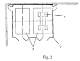
- FIG. 1 of the appended drawings represents a cabin, which is essentially in the form of a closed enclosure 1.
- this cabin is intended for the implementation of a process for the preparation of surfaces to be painted and for painting of these surfaces, which consists in carrying out all of the preparation and painting operations in said same enclosure. closed 1, under a slight overpressure of air, without displacement of the object to be treated, the painting operations triggering an impossibility of implementing all the other preparation and drying operations.
- the cabin forming the closed enclosure 1 comprises at least one work station 2, a single overpressure ventilation group 3, at least one lifting table 4, at least one satellite 5 for power distribution and control for the tools necessary for carrying out the various operations, by work station 2, by at least one disconnectable painting equipment 6 and by at least one radiation drying means 7.
- the preparation and painting operations are carried out in said same closed enclosure 1, under a slight air pressure, without movement of the object to be treated and the painting operations trigger an impossibility of implementing all the other preparation and drying operations.
- the preparation operations consist of straightening bumpy surfaces, then puttying these surfaces on a work station 2, and possibly on the lifting table 4 of this station 2, the putty being followed by a period of deep drying of the sealants and primers via the radiation drying means 7. After this drying, a sanding operation is carried out with the use of a suction sander connected to the power distribution and control satellite 5.
- the slight overpressure of air is ensured by the single overpressure ventilation group 3, which is connected to the enclosure 1, on the one hand, via blowing ducts 8 to at least one plenum 9 extending above work station 2 and, on the other hand, by means of extraction ducts 10 to at least one box 11 provided with a grating 12, the blowing 8 and extraction ducts 10 being each provided with 'a corresponding valve 8' and 10 '( Figure 1).
- This overpressure ventilation group 3 is advantageously coupled to a heating means making it possible to simultaneously maintain the temperature of the enclosure 1 during cold periods.
- the lifting table 4 is of known type, in particular in the field of automobile repair, and is not described in more detail. Such a table essentially makes it possible to ensure perfect ergonomics of the work station and is embedded in the ground at the level of the grating 12 in the non-use position, thus freeing up an additional working surface.
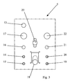
- Each energy distribution and control satellite 5 for the tools necessary for carrying out the various operations is advantageously in the form of a box mounted in the wall of the enclosure 1 and connected to the means for distributing electrical energy and pneumatic, this box comprising on the front side the necessary connection means, namely at least one electrical outlet 13, a regulated air intake 14, an unregulated air intake 15, a device 16 for adjusting the pressure of the regulated air intake 14, a pressure gauge 17, a sanding dust intake 18, a set 19 to 22 of air intakes 19, 20 for spraying and controlling disconnectable paint 6, pressure adjustment 21 spray and pressure gauge 22 for controlling the spray pressure and by a valve 23 for controlling the intake 18 for sanding dust suction (FIG. 3).
- the single overpressure ventilation group 3 is further provided, in the case of construction of the enclosure, with several work stations, of a reversing valve 24 for controlling the suction circuit, intended to allow operation with total or recycled air renewal during cold periods, as well as making a preferential choice of operation for the single overpressure ventilation group 3 in relation to a workstation 2.
- a reversing valve 24 for controlling the suction circuit, intended to allow operation with total or recycled air renewal during cold periods, as well as making a preferential choice of operation for the single overpressure ventilation group 3 in relation to a workstation 2.
- the radiation drying means 7 is preferably constituted by at least one ramp with infrared or ultraviolet radiation and is advantageously mounted in the enclosure 1 in a movable manner along a horizontal axis passing through the entire enclosure 1 under the plenum 9.
- This means 7 can, moreover, be adjustable in position relative to the plenum 9.
- a single radiation drying means 7 is sufficient for all of the work stations 2, so that the investment is reduced correspondingly.
- the enclosure 1 proper is produced in the form of a fully closed sheet steel carcass and provided with rigid or flexible access doors in the form of curtains made of a material having a fire resistance of M0 quality.
- This enclosure 1 is further provided with multiple light sources, a prefilter on the air inlet and diffusing filters in the plenum (s) 9 to stop the introduction of dust into the enclosure 1 and an extraction filter under the grating or gratings 12, in order to retain the primer or paint pigments before air is released to the atmosphere.
- the enclosure 1 may include a straightening device, not shown. Such a straightening device is of perfectly known type and can be fixed in a removable manner either in a rail fixed to the ground or integrated into the ground or else in a rail fixed on the grating or be fixed directly on the grating.
- the sanding operation is carried out with a connected suction sander, for its drive to the regulated air intake 14, and for the evacuation of sanding dust at the suction outlet 18 for sanding dust from the power distribution and control satellite 5.
- a connected suction sander for its drive to the regulated air intake 14, and for the evacuation of sanding dust at the suction outlet 18 for sanding dust from the power distribution and control satellite 5.
- the dust produced is captured approximately 80% by the sander itself and the remaining 20% is entrained by the air flow due to ventilation, so that it does not pollute the working environment of the neighboring station (s).
- the suction of the dust by means of the socket 18 is triggered by means of the control valve 23.
- valves 8 'and 10' which allow the distribution of pressurized air in the plenums 9 and therefore above the workstations 2.
- These valves 8 ' also allow distribution over a single workstation during a painting operation and then automatically shut off the air supply above the workstation (s) 2.
- the reversing valve 24 for controlling the suction circuit also allows air recycling, the remaining dust being retained at the level of the prefilters and filters equipping the plenum (s) 9 and the grating (s) 12 .
- the masking, the priming of the surfaces and the sanding of the primers are carried out under a slight overpressure of air due to the continuous operation of the ventilation group at overpressure 3. Then, and always under the same overpressure of air, cleaning is carried out before application of the paint, namely, for example, by means of an air jet distributed by an air gun connected to the unregulated air intake 15, and the final painting of surfaces.
- the process consists, at the start of the operations, of automatically switching on the ventilation group by overpressure 3.
- the method also consists in preventing an operation of any of the preparation devices or of the radiation drying means 7 as soon as the disconnectable paint equipment 6 is connected to the distribution satellite of energy and control 5 and to concentrate ventilation on the only work station 2 on which painting is carried out.
- the satellite 5 is provided, at the air intakes 19 and 20 for connecting the disconnectable paint equipment 6, with air flow detectors connected to an interruption control of all of the other ways to distribution of energy to the accessories of all the satellites 5, with the exception of the overpressure ventilation group 3, and to the control of the valves 8 'of the plenums 9.
- This interruption command, actuated by the detectors, is all or nothing type, that is to say that it does not allow any of the accessory devices and the radiation drying means to operate, and that it automatically switches the ventilation air supply above the work station 2 concerned, by controlling the valves 8 '.
- the method also consists in automatically carrying out an operation control of the overpressure ventilation group 3 in the polluted air extraction mode with prohibition of any operation, as soon as the painting operation using disconnectable painting equipment (6).
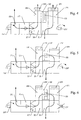
- FIGS. 4 to 15 of the accompanying drawings show different possible embodiments of the ventilation unit 3, respectively in positions of exhaust air, recirculation of air with renewal and recirculation of total air, in relation to the operation of disconnectable paint equipment 6.
- the ventilation unit 3 which is essentially constituted by a heating means 25, by a box 26 for blowing air towards the plenum, by prefilters 27 and by conduits 28 and 29, respectively for intake of fresh air and rejection of stale air, each equipped with a ventilation means with drive motor 28 "and 29", is provided at the conduits 28 and 29 of shut-off valves 28 ′ and 29 ′ and, on the conduits 28 and 29, respectively for suction of fresh air and rejection of stale air, distribution boxes 30 and 31 and, between said conduits 28 and 29 , a bypass duct 32 provided with a bypass valve 33.
- the fresh air sucked through the conduit 28, in the valve open position 28 ' goes through the distribution box 30, the prefilters 27 and the blowing box 26 to be propelled into the plenum and towards the corresponding work station.
- the air coming from said work station is sucked through the grating 12 of the box 11 (FIG. 1) by the bottom of the distribution box 31 connected to the exhaust air discharge duct 29 and evacuated to outside through the valve 29 'in the open position, the bypass valve 33 being closed.
- the ventilation unit 3 operates in the configuration shown in FIG. 5 of the appended drawings, namely a configuration allowing energy saving and in which the air coming from the work station (s) is sucked through the grating 12 of the box 11 ( Figure 1) from the bottom of the distribution box 31 connected to the exhaust air discharge duct 29 and is recirculated to the plenum by passage in the duct 28 through the bypass valve 33 open and the distribution box 30, the prefilters 27, the heating means 25 and the blowing box 26, the closing valves 28 'and 29' of the conduits 28 and 29 being closed.
- the ventilation means with drive motor 28 "and 29" equipping the conduits 28 and 29 are on.
- FIGs 7 to 9 of the accompanying drawings show an alternative embodiment of the ventilation group, in which the ducts 28 and 29 respectively for air intake 9 and exhaust of stale air are connected to distribution boxes 30 and 31 , these boxes being provided with valves 30'-31 'and 30 "-31" opening respectively on the side of the inlet of the suction duct 28 and on the side of the air intake which is connected to the work station through the grating 12 of the box 11 ( Figure 1).
- the air coming from said work station is sucked through the grating 12 of the box 11 (FIG. 1) from the bottom of the distribution box 31 through the valve 31 "in the open position and discharged to the outside through the exhaust air discharge duct 29 connected to said distribution box 31, the valve 31 'being closed.
- Figure 8 of the accompanying drawings shows an operating configuration in energy saving mode, in which the air from the workstation (s) is sucked through the grating 12 of the box 11 ( Figure 1) from below distribution box 30 connected to the fresh air suction duct 28 through the valve 30 "in the open position and is recirculated to the plenum by passage through the prefilters 27, the heating means 25 and the blowing box 26, the valves 30 'and 31 "being closed, while the fresh air sucked through the duct 28 passes through the open valve 31' of the distribution box 31 and said box 31, directly in the pipe 29 exhaust air discharge.
- the drive motors 28 "and 29" of the ventilation means operate in an identical manner to that described in connection with FIGS. 4 and 5.
- FIG. 9 represents the ventilation group 3 in operation in the drying phase.
- the air from the workstation (s) is sucked through the grating 12 of the box 11 (FIG. 1) from the bottom of the distribution box 30 through the valve 30 "in the open position and follows the same path as that described with regard to FIG. 8.
- the heating means 25 is running while the drive motor 29 "of the ventilation means equipping the duct 29 is stopped, so that the air recycled through the heating means 25 is heated to promote the drying process.
- FIGs 10 to 12 show an alternative embodiment of the ventilation unit 3, according to Figures 7 to 9, in which the distribution box 30 is integrated in the duct 28 for suction of fresh air and the distribution box 31 is associated with the exhaust air discharge duct 29, the said distribution box 31 being connected, by its end opposite to that of the return of the stale air, to the inlet of the fresh air suction duct 28, by the through a connection duct 34, with interposition of a valve 31 '.
- the air coming from said work station is sucked through the grating 12 of the box 11 (FIG. 1) from the bottom of the distribution box 31 through the valve 31 "in the open position and evacuated outside through the exhaust air discharge duct 29 connected to said distribution box 31, the valve 31 'being closed.
- the ventilation unit 3 operates in an energy-saving configuration, in which the air coming from the work station (s) is sucked through the grating 12 of the box 11 (FIG. 1) from the bottom of the distribution box 30 and is recirculated to the plenum through the prefilters 27, the heating means 25 and the blowing box 26, the valves 30 'and 31 "being closed, while the fresh air sucked through the duct 28 passes through the connection duct 34, the open valve 31 'of the distribution box 31 and said box 31, directly in the duct 29 for rejecting stale air.
- ventilation group 3 is identical to that described with regard to ventilation group 3 according to FIG. 9.
- FIGS. 13 to 15 represent another alternative embodiment of the ventilation group 3, simplified, in which the conduits 28 and 29, respectively for suction of fresh air and rejection of stale air, are completely independent by construction and integrate each a distribution box 30 and 31 provided at its ends with valves 30'-30 "and 31'-31", the exhaust air discharge duct being devoid of a ventilation means.
- the air coming from said work station is sucked through the grating 12 of the box 11 (FIG. 1) from the bottom of the distribution box 31 through the valves 31 'and 31 ".
- this ventilation group 3 operates in an identical manner to that according to the embodiment of FIGS. 11 and 12.
- the enclosure 1 is provided with a control and electrical protection box, not shown, ensuring control and optimal use of the cabin and all the servo and safety means.
- the prefilters and filters of the plenums 9 and the filters of the gratings 12 are each advantageously connected to a pressure switch or to a pressure gauge making it possible, by monitoring the air pressure prevailing at the level of these elements, to detect their degree of clogging and to thus plan the interventions possibly necessary.
- the method according to the invention makes it possible to prevent any production of dust pollution during the painting phase and also avoids any risk of ignition of the solvents by a spark due to an electrical device.
- the booth according to the invention meets the standards and recommendations applying to paint booths.
- the method according to the invention implemented with the cabin described above makes it possible to guarantee an operation which does not depend on manual intervention by the operator, the use of the various tools or accessories automatically triggering operating phases. and which may prohibit the simultaneous conduct of certain operations.
- an external thermostat can be provided to carry out an assisted control of the air distribution and its possible recycling.
- the invention it is possible to produce a booth for preparing surfaces to be painted and painting these surfaces in the same enclosure making it possible to carry out all of the operations for treating an object to be treated in one place and without moving said object, by optimizing the various operations. This results in a significant gain in productivity, because the handling times which have existed until now between the different operations carried out on different stations are eliminated.
- the object can be treated safely by the user, in a relatively small space and in full compliance with the standards and recommendations in force.
- the method and the cabin according to the invention allow a significant improvement in ergonomics compared to cabins known to date, so that the quality of the work performed is also improved.
- the invention has been described in connection with a cabin more particularly suited to the field of automobile repair. However, the invention is also applicable for the surface treatment of other objects.
Landscapes
- Drying Of Solid Materials (AREA)
- Details Or Accessories Of Spraying Plant Or Apparatus (AREA)
- Application Of Or Painting With Fluid Materials (AREA)
- Vehicle Cleaning, Maintenance, Repair, Refitting, And Outriggers (AREA)
- Automobile Manufacture Line, Endless Track Vehicle, Trailer (AREA)
- Coating Apparatus (AREA)
Applications Claiming Priority (2)
| Application Number | Priority Date | Filing Date | Title |
|---|---|---|---|
| FR0213122 | 2002-10-21 | ||
| FR0213122A FR2845935B1 (fr) | 2002-10-21 | 2002-10-21 | Procede et cabine de preparation de surfaces a peindre et de peinture de ces surfaces dans une meme enceinte |
Publications (2)
| Publication Number | Publication Date |
|---|---|
| EP1413362A1 true EP1413362A1 (de) | 2004-04-28 |
| EP1413362B1 EP1413362B1 (de) | 2008-05-14 |
Family
ID=32050609
Family Applications (1)
| Application Number | Title | Priority Date | Filing Date |
|---|---|---|---|
| EP03360115A Revoked EP1413362B1 (de) | 2002-10-21 | 2003-10-07 | Verfahren und Kabine zur Vorbereitung und Lackierung von Oberflächen im selben Raum |
Country Status (5)
| Country | Link |
|---|---|
| EP (1) | EP1413362B1 (de) |
| AT (1) | ATE395146T1 (de) |
| DE (1) | DE60320915D1 (de) |
| ES (1) | ES2306848T3 (de) |
| FR (1) | FR2845935B1 (de) |
Cited By (7)
| Publication number | Priority date | Publication date | Assignee | Title |
|---|---|---|---|---|
| FR2973261A1 (fr) * | 2011-04-04 | 2012-10-05 | Omia Soc | Procede de finition de la peinture d'un vehicule et dispositif associe |
| WO2016037875A1 (de) * | 2014-09-12 | 2016-03-17 | Spieker Jürgen | Modularer kombinations-arbeitsplatz |
| CN105903626A (zh) * | 2016-07-12 | 2016-08-31 | 无锡顺达智能自动化工程股份有限公司 | 改进式水旋喷漆室底部结构 |
| CN105903625A (zh) * | 2016-07-12 | 2016-08-31 | 无锡顺达智能自动化工程股份有限公司 | 油淋式多功能表面处理设备 |
| CN107009236A (zh) * | 2017-06-06 | 2017-08-04 | 吉林麦达斯铝业有限公司 | 轨道列车车体大部件打磨用龙门式砂带机 |
| CN109225739A (zh) * | 2018-11-05 | 2019-01-18 | 曾斌文 | 一种汽车维修涂装多功能平台 |
| CN113182104A (zh) * | 2021-03-31 | 2021-07-30 | 安徽省汉帮家具制造有限公司 | 一种办公家具板材表面处理方法 |
Families Citing this family (1)
| Publication number | Priority date | Publication date | Assignee | Title |
|---|---|---|---|---|
| CN112642628B (zh) * | 2020-12-27 | 2022-09-23 | 山东鑫迈机电科技股份有限公司 | 一种智能的钢塑复合管内除铁喷塑机构及其喷塑方法 |
Citations (5)
| Publication number | Priority date | Publication date | Assignee | Title |
|---|---|---|---|---|
| DE508557C (de) | 1925-12-09 | 1930-09-27 | Albert Krautzberger | Staubsammler und Trockenraum zur Verwendung in der Spritzmalerei |
| US4106430A (en) | 1976-03-26 | 1978-08-15 | Nippon Paint Co., Ltd. | Single chamber type coating and baking apparatus |
| US4537120A (en) | 1982-04-30 | 1985-08-27 | Flakt Aktiebolag | Surface treatment plant and a method of ventilating same |
| JPH105858A (ja) | 1996-06-28 | 1998-01-13 | Kana Flex Corp Kk | 鋼板補強芯入りダクトホース及びその製造方法 |
| JPH1057858A (ja) * | 1996-08-20 | 1998-03-03 | Banzai:Kk | 板金塗装用吸塵装置 |
-
2002
- 2002-10-21 FR FR0213122A patent/FR2845935B1/fr not_active Expired - Fee Related
-
2003
- 2003-10-07 DE DE60320915T patent/DE60320915D1/de not_active Expired - Lifetime
- 2003-10-07 AT AT03360115T patent/ATE395146T1/de not_active IP Right Cessation
- 2003-10-07 EP EP03360115A patent/EP1413362B1/de not_active Revoked
- 2003-10-07 ES ES03360115T patent/ES2306848T3/es not_active Expired - Lifetime
Patent Citations (5)
| Publication number | Priority date | Publication date | Assignee | Title |
|---|---|---|---|---|
| DE508557C (de) | 1925-12-09 | 1930-09-27 | Albert Krautzberger | Staubsammler und Trockenraum zur Verwendung in der Spritzmalerei |
| US4106430A (en) | 1976-03-26 | 1978-08-15 | Nippon Paint Co., Ltd. | Single chamber type coating and baking apparatus |
| US4537120A (en) | 1982-04-30 | 1985-08-27 | Flakt Aktiebolag | Surface treatment plant and a method of ventilating same |
| JPH105858A (ja) | 1996-06-28 | 1998-01-13 | Kana Flex Corp Kk | 鋼板補強芯入りダクトホース及びその製造方法 |
| JPH1057858A (ja) * | 1996-08-20 | 1998-03-03 | Banzai:Kk | 板金塗装用吸塵装置 |
Non-Patent Citations (1)
| Title |
|---|
| PATENT ABSTRACTS OF JAPAN vol. 1998, no. 08 30 June 1998 (1998-06-30) * |
Cited By (8)
| Publication number | Priority date | Publication date | Assignee | Title |
|---|---|---|---|---|
| FR2973261A1 (fr) * | 2011-04-04 | 2012-10-05 | Omia Soc | Procede de finition de la peinture d'un vehicule et dispositif associe |
| WO2016037875A1 (de) * | 2014-09-12 | 2016-03-17 | Spieker Jürgen | Modularer kombinations-arbeitsplatz |
| CN105903626A (zh) * | 2016-07-12 | 2016-08-31 | 无锡顺达智能自动化工程股份有限公司 | 改进式水旋喷漆室底部结构 |
| CN105903625A (zh) * | 2016-07-12 | 2016-08-31 | 无锡顺达智能自动化工程股份有限公司 | 油淋式多功能表面处理设备 |
| CN105903625B (zh) * | 2016-07-12 | 2018-02-16 | 无锡顺达智能自动化工程股份有限公司 | 油淋式多功能表面处理设备 |
| CN107009236A (zh) * | 2017-06-06 | 2017-08-04 | 吉林麦达斯铝业有限公司 | 轨道列车车体大部件打磨用龙门式砂带机 |
| CN109225739A (zh) * | 2018-11-05 | 2019-01-18 | 曾斌文 | 一种汽车维修涂装多功能平台 |
| CN113182104A (zh) * | 2021-03-31 | 2021-07-30 | 安徽省汉帮家具制造有限公司 | 一种办公家具板材表面处理方法 |
Also Published As
| Publication number | Publication date |
|---|---|
| FR2845935A1 (fr) | 2004-04-23 |
| DE60320915D1 (de) | 2008-06-26 |
| ATE395146T1 (de) | 2008-05-15 |
| ES2306848T3 (es) | 2008-11-16 |
| EP1413362B1 (de) | 2008-05-14 |
| FR2845935B1 (fr) | 2005-06-17 |
Similar Documents
| Publication | Publication Date | Title |
|---|---|---|
| EP1413362B1 (de) | Verfahren und Kabine zur Vorbereitung und Lackierung von Oberflächen im selben Raum | |
| FR2495964A1 (fr) | Procede et dispositif pour le traitement de surface d'objets | |
| EP2519360B1 (de) | Verfahren zur oberflächenbehandlung von breiten teilen, zur umsetzung dieses verfahrens geeigneter greifer oder teile, verwendung des greifers und behandlungskabine | |
| FR2918302A1 (fr) | Procede de nettoyage d'un pulverisateur de texture. | |
| FR2525926A1 (fr) | Installation de traitement de surface et procede pour sa ventilation | |
| EP0691892B1 (de) | Farbspritzanlage | |
| EP2181774B1 (de) | Verfahren zur Verwaltung vom Energieverbrauch in einem Arbeitsraum und Vorrichtung zum Ausführen dieses Verfahrens | |
| FR2698292A1 (fr) | Installation de peinture à poudre munie d'une cabine à section variable. | |
| WO2018019472A1 (fr) | Lance pour le nettoyage, la desinfection et l'assainissement, de tous types d'objets, integrant un generateur de vapeur, procedes de fonctionnement associes | |
| EP0549474B1 (de) | Heiz- und/oder Klimaanlage für den Innenraum von Kraftfahrzeugen mit Luftfiltermitteln | |
| EP0795360A1 (de) | Verfahren und Vorrichtung zur Reinigung von Rohren | |
| EP3915365B1 (de) | Auffangplatte für landwirtschaftliches sprühsystem | |
| CN111451066A (zh) | 用于汽车内饰的喷涂机 | |
| EP0723817A1 (de) | Kabine zur Spritzbehandlung von Werkstücken | |
| CN213102890U (zh) | 一种涂层涂覆用高效速干装置 | |
| EP0422980B1 (de) | Fahrbare Lüftungsanlage | |
| KR102515082B1 (ko) | 친환경 스마트 오일스테인 자동 도포장치 | |
| CN120421147B (zh) | 一种通信设备外壳维护用喷漆装置 | |
| FR2824000A1 (fr) | Procede et installation de traitement d'objets par projection manuelle de brouillard a rideau d'air de protection | |
| FR2791283A1 (fr) | Procede de nettoyage et installation de sechage d'un habitacle de vehicule automobile | |
| CN220503642U (zh) | 一种道路划线装置 | |
| US20250256298A1 (en) | Vacuum coating system | |
| FR2813909A1 (fr) | Cabine de poncage ou analogue | |
| EP1134506A1 (de) | Arbeitskabine für Naturwerkstein mit geregelter Atmosphäre | |
| WO2017134386A1 (fr) | Véhicule-atelier avec cabine de peinture |
Legal Events
| Date | Code | Title | Description |
|---|---|---|---|
| PUAI | Public reference made under article 153(3) epc to a published international application that has entered the european phase |
Free format text: ORIGINAL CODE: 0009012 |
|
| AK | Designated contracting states |
Kind code of ref document: A1 Designated state(s): AT BE BG CH CY CZ DE DK EE ES FI FR GB GR HU IE IT LI LU MC NL PT RO SE SI SK TR |
|
| AX | Request for extension of the european patent |
Extension state: AL LT LV MK |
|
| 17P | Request for examination filed |
Effective date: 20041020 |
|
| AKX | Designation fees paid |
Designated state(s): AT BE BG CH CY CZ DE DK EE ES FI FR GB GR HU IE IT LI LU MC NL PT RO SE SI SK TR |
|
| AXX | Extension fees paid |
Extension state: MK Payment date: 20041020 |
|
| GRAP | Despatch of communication of intention to grant a patent |
Free format text: ORIGINAL CODE: EPIDOSNIGR1 |
|
| GRAS | Grant fee paid |
Free format text: ORIGINAL CODE: EPIDOSNIGR3 |
|
| GRAA | (expected) grant |
Free format text: ORIGINAL CODE: 0009210 |
|
| AK | Designated contracting states |
Kind code of ref document: B1 Designated state(s): AT BE BG CH CY CZ DE DK EE ES FI FR GB GR HU IE IT LI LU MC NL PT RO SE SI SK TR |
|
| AX | Request for extension of the european patent |
Extension state: MK |
|
| REG | Reference to a national code |
Ref country code: GB Ref legal event code: FG4D Free format text: NOT ENGLISH |
|
| REG | Reference to a national code |
Ref country code: CH Ref legal event code: EP |
|
| REG | Reference to a national code |
Ref country code: IE Ref legal event code: FG4D |
|
| REF | Corresponds to: |
Ref document number: 60320915 Country of ref document: DE Date of ref document: 20080626 Kind code of ref document: P |
|
| REG | Reference to a national code |
Ref country code: CH Ref legal event code: NV Representative=s name: SCHNEIDER FELDMANN AG PATENT- UND MARKENANWAELTE |
|
| PG25 | Lapsed in a contracting state [announced via postgrant information from national office to epo] |
Ref country code: SI Free format text: LAPSE BECAUSE OF FAILURE TO SUBMIT A TRANSLATION OF THE DESCRIPTION OR TO PAY THE FEE WITHIN THE PRESCRIBED TIME-LIMIT Effective date: 20080514 |
|
| PG25 | Lapsed in a contracting state [announced via postgrant information from national office to epo] |
Ref country code: FI Free format text: LAPSE BECAUSE OF FAILURE TO SUBMIT A TRANSLATION OF THE DESCRIPTION OR TO PAY THE FEE WITHIN THE PRESCRIBED TIME-LIMIT Effective date: 20080514 |
|
| NLV1 | Nl: lapsed or annulled due to failure to fulfill the requirements of art. 29p and 29m of the patents act | ||
| REG | Reference to a national code |
Ref country code: ES Ref legal event code: FG2A Ref document number: 2306848 Country of ref document: ES Kind code of ref document: T3 |
|
| PG25 | Lapsed in a contracting state [announced via postgrant information from national office to epo] |
Ref country code: AT Free format text: LAPSE BECAUSE OF FAILURE TO SUBMIT A TRANSLATION OF THE DESCRIPTION OR TO PAY THE FEE WITHIN THE PRESCRIBED TIME-LIMIT Effective date: 20080514 Ref country code: NL Free format text: LAPSE BECAUSE OF FAILURE TO SUBMIT A TRANSLATION OF THE DESCRIPTION OR TO PAY THE FEE WITHIN THE PRESCRIBED TIME-LIMIT Effective date: 20080514 |
|
| REG | Reference to a national code |
Ref country code: IE Ref legal event code: FD4D |
|
| PG25 | Lapsed in a contracting state [announced via postgrant information from national office to epo] |
Ref country code: CZ Free format text: LAPSE BECAUSE OF FAILURE TO SUBMIT A TRANSLATION OF THE DESCRIPTION OR TO PAY THE FEE WITHIN THE PRESCRIBED TIME-LIMIT Effective date: 20080514 Ref country code: DK Free format text: LAPSE BECAUSE OF FAILURE TO SUBMIT A TRANSLATION OF THE DESCRIPTION OR TO PAY THE FEE WITHIN THE PRESCRIBED TIME-LIMIT Effective date: 20080514 Ref country code: PT Free format text: LAPSE BECAUSE OF FAILURE TO SUBMIT A TRANSLATION OF THE DESCRIPTION OR TO PAY THE FEE WITHIN THE PRESCRIBED TIME-LIMIT Effective date: 20081014 Ref country code: SE Free format text: LAPSE BECAUSE OF FAILURE TO SUBMIT A TRANSLATION OF THE DESCRIPTION OR TO PAY THE FEE WITHIN THE PRESCRIBED TIME-LIMIT Effective date: 20080814 Ref country code: IE Free format text: LAPSE BECAUSE OF FAILURE TO SUBMIT A TRANSLATION OF THE DESCRIPTION OR TO PAY THE FEE WITHIN THE PRESCRIBED TIME-LIMIT Effective date: 20080514 |
|
| PGFP | Annual fee paid to national office [announced via postgrant information from national office to epo] |
Ref country code: TR Payment date: 20081003 Year of fee payment: 6 |
|
| PLBI | Opposition filed |
Free format text: ORIGINAL CODE: 0009260 |
|
| PG25 | Lapsed in a contracting state [announced via postgrant information from national office to epo] |
Ref country code: RO Free format text: LAPSE BECAUSE OF FAILURE TO SUBMIT A TRANSLATION OF THE DESCRIPTION OR TO PAY THE FEE WITHIN THE PRESCRIBED TIME-LIMIT Effective date: 20080514 Ref country code: SK Free format text: LAPSE BECAUSE OF FAILURE TO SUBMIT A TRANSLATION OF THE DESCRIPTION OR TO PAY THE FEE WITHIN THE PRESCRIBED TIME-LIMIT Effective date: 20080514 |
|
| 26 | Opposition filed |
Opponent name: OMIA Effective date: 20090206 |
|
| PLAX | Notice of opposition and request to file observation + time limit sent |
Free format text: ORIGINAL CODE: EPIDOSNOBS2 |
|
| PG25 | Lapsed in a contracting state [announced via postgrant information from national office to epo] |
Ref country code: EE Free format text: LAPSE BECAUSE OF FAILURE TO SUBMIT A TRANSLATION OF THE DESCRIPTION OR TO PAY THE FEE WITHIN THE PRESCRIBED TIME-LIMIT Effective date: 20080514 Ref country code: BG Free format text: LAPSE BECAUSE OF FAILURE TO SUBMIT A TRANSLATION OF THE DESCRIPTION OR TO PAY THE FEE WITHIN THE PRESCRIBED TIME-LIMIT Effective date: 20080814 |
|
| PG25 | Lapsed in a contracting state [announced via postgrant information from national office to epo] |
Ref country code: MC Free format text: LAPSE BECAUSE OF NON-PAYMENT OF DUE FEES Effective date: 20081031 |
|
| PGFP | Annual fee paid to national office [announced via postgrant information from national office to epo] |
Ref country code: GB Payment date: 20081029 Year of fee payment: 6 |
|
| PLAF | Information modified related to communication of a notice of opposition and request to file observations + time limit |
Free format text: ORIGINAL CODE: EPIDOSCOBS2 |
|
| PLBB | Reply of patent proprietor to notice(s) of opposition received |
Free format text: ORIGINAL CODE: EPIDOSNOBS3 |
|
| PG25 | Lapsed in a contracting state [announced via postgrant information from national office to epo] |
Ref country code: HU Free format text: LAPSE BECAUSE OF FAILURE TO SUBMIT A TRANSLATION OF THE DESCRIPTION OR TO PAY THE FEE WITHIN THE PRESCRIBED TIME-LIMIT Effective date: 20081115 Ref country code: CY Free format text: LAPSE BECAUSE OF FAILURE TO SUBMIT A TRANSLATION OF THE DESCRIPTION OR TO PAY THE FEE WITHIN THE PRESCRIBED TIME-LIMIT Effective date: 20080514 Ref country code: LU Free format text: LAPSE BECAUSE OF NON-PAYMENT OF DUE FEES Effective date: 20081007 |
|
| PG25 | Lapsed in a contracting state [announced via postgrant information from national office to epo] |
Ref country code: GR Free format text: LAPSE BECAUSE OF FAILURE TO SUBMIT A TRANSLATION OF THE DESCRIPTION OR TO PAY THE FEE WITHIN THE PRESCRIBED TIME-LIMIT Effective date: 20080815 |
|
| PG25 | Lapsed in a contracting state [announced via postgrant information from national office to epo] |
Ref country code: GB Free format text: LAPSE BECAUSE OF NON-PAYMENT OF DUE FEES Effective date: 20091007 |
|
| PLAB | Opposition data, opponent's data or that of the opponent's representative modified |
Free format text: ORIGINAL CODE: 0009299OPPO |
|
| R26 | Opposition filed (corrected) |
Opponent name: OMIA Effective date: 20090206 |
|
| RDAF | Communication despatched that patent is revoked |
Free format text: ORIGINAL CODE: EPIDOSNREV1 |
|
| APBM | Appeal reference recorded |
Free format text: ORIGINAL CODE: EPIDOSNREFNO |
|
| APBP | Date of receipt of notice of appeal recorded |
Free format text: ORIGINAL CODE: EPIDOSNNOA2O |
|
| APAH | Appeal reference modified |
Free format text: ORIGINAL CODE: EPIDOSCREFNO |
|
| APBQ | Date of receipt of statement of grounds of appeal recorded |
Free format text: ORIGINAL CODE: EPIDOSNNOA3O |
|
| PG25 | Lapsed in a contracting state [announced via postgrant information from national office to epo] |
Ref country code: TR Free format text: LAPSE BECAUSE OF NON-PAYMENT OF DUE FEES Effective date: 20091007 |
|
| APBU | Appeal procedure closed |
Free format text: ORIGINAL CODE: EPIDOSNNOA9O |
|
| PGFP | Annual fee paid to national office [announced via postgrant information from national office to epo] |
Ref country code: DE Payment date: 20131018 Year of fee payment: 11 |
|
| POAC | Information related to number of petition for review modified |
Free format text: ORIGINAL CODE: EPIDOSCPRV1 |
|
| POAG | Date of filing of petition for review recorded |
Free format text: ORIGINAL CODE: EPIDOSNPRV3 |
|
| POAH | Number of petition for review recorded |
Free format text: ORIGINAL CODE: EPIDOSNPRV1 |
|
| POAI | Petitioner in petition for review recorded |
Free format text: ORIGINAL CODE: EPIDOSNPRV2 |
|
| PGFP | Annual fee paid to national office [announced via postgrant information from national office to epo] |
Ref country code: CH Payment date: 20140127 Year of fee payment: 11 |
|
| POAK | Decision taken: petition for review obviously unsubstantiated |
Free format text: ORIGINAL CODE: 0009255 |
|
| PRVN | Petition for review not allowed |
Free format text: PETITION FOR REVIEW OBVIOUSLY INADMISSABLE (NOT DEEMED TO BE FILED) OR SIMULTANEOUSLY OBVIOUSLY INADMISSABLE AND OBVIOUSLY UNSUBSTANTIATED Effective date: 20140707 |
|
| REG | Reference to a national code |
Ref country code: DE Ref legal event code: R119 Ref document number: 60320915 Country of ref document: DE |
|
| REG | Reference to a national code |
Ref country code: CH Ref legal event code: PL |
|
| PG25 | Lapsed in a contracting state [announced via postgrant information from national office to epo] |
Ref country code: CH Free format text: LAPSE BECAUSE OF NON-PAYMENT OF DUE FEES Effective date: 20141031 Ref country code: DE Free format text: LAPSE BECAUSE OF NON-PAYMENT OF DUE FEES Effective date: 20150501 Ref country code: LI Free format text: LAPSE BECAUSE OF NON-PAYMENT OF DUE FEES Effective date: 20141031 |
|
| REG | Reference to a national code |
Ref country code: FR Ref legal event code: PLFP Year of fee payment: 13 |
|
| RDAE | Information deleted related to despatch of communication that patent is revoked |
Free format text: ORIGINAL CODE: EPIDOSDREV1 |
|
| RDAF | Communication despatched that patent is revoked |
Free format text: ORIGINAL CODE: EPIDOSNREV1 |
|
| PLAB | Opposition data, opponent's data or that of the opponent's representative modified |
Free format text: ORIGINAL CODE: 0009299OPPO |
|
| R26 | Opposition filed (corrected) |
Opponent name: OMIA Effective date: 20090206 |
|
| APBM | Appeal reference recorded |
Free format text: ORIGINAL CODE: EPIDOSNREFNO |
|
| APBP | Date of receipt of notice of appeal recorded |
Free format text: ORIGINAL CODE: EPIDOSNNOA2O |
|
| APAH | Appeal reference modified |
Free format text: ORIGINAL CODE: EPIDOSCREFNO |
|
| APBQ | Date of receipt of statement of grounds of appeal recorded |
Free format text: ORIGINAL CODE: EPIDOSNNOA3O |
|
| RAP2 | Party data changed (patent owner data changed or rights of a patent transferred) |
Owner name: WEINMANN TECHNOLOGIES ( SOCIETE A RESPONSABILITE L |
|
| REG | Reference to a national code |
Ref country code: FR Ref legal event code: PLFP Year of fee payment: 14 |
|
| PLAB | Opposition data, opponent's data or that of the opponent's representative modified |
Free format text: ORIGINAL CODE: 0009299OPPO |
|
| R26 | Opposition filed (corrected) |
Opponent name: OMIA Effective date: 20090206 |
|
| PGFP | Annual fee paid to national office [announced via postgrant information from national office to epo] |
Ref country code: FR Payment date: 20161021 Year of fee payment: 14 |
|
| PGFP | Annual fee paid to national office [announced via postgrant information from national office to epo] |
Ref country code: ES Payment date: 20161026 Year of fee payment: 14 Ref country code: BE Payment date: 20161027 Year of fee payment: 14 Ref country code: IT Payment date: 20161024 Year of fee payment: 14 |
|
| REG | Reference to a national code |
Ref country code: DE Ref legal event code: R064 Ref document number: 60320915 Country of ref document: DE Ref country code: DE Ref legal event code: R103 Ref document number: 60320915 Country of ref document: DE |
|
| APBU | Appeal procedure closed |
Free format text: ORIGINAL CODE: EPIDOSNNOA9O |
|
| RDAG | Patent revoked |
Free format text: ORIGINAL CODE: 0009271 |
|
| STAA | Information on the status of an ep patent application or granted ep patent |
Free format text: STATUS: PATENT REVOKED |
|
| 27W | Patent revoked |
Effective date: 20170426 |