EP1413410B1 - Zerkleinerungsmachine mit rotierendem Messerkranz - Google Patents
Zerkleinerungsmachine mit rotierendem Messerkranz Download PDFInfo
- Publication number
- EP1413410B1 EP1413410B1 EP03256191A EP03256191A EP1413410B1 EP 1413410 B1 EP1413410 B1 EP 1413410B1 EP 03256191 A EP03256191 A EP 03256191A EP 03256191 A EP03256191 A EP 03256191A EP 1413410 B1 EP1413410 B1 EP 1413410B1
- Authority
- EP
- European Patent Office
- Prior art keywords
- knife
- end plates
- assembly
- base
- apertures
- Prior art date
- Legal status (The legal status is an assumption and is not a legal conclusion. Google has not performed a legal analysis and makes no representation as to the accuracy of the status listed.)
- Expired - Lifetime
Links
- 230000000712 assembly Effects 0.000 claims abstract description 29
- 238000000429 assembly Methods 0.000 claims abstract description 29
- 238000005520 cutting process Methods 0.000 claims abstract description 20
- 239000002023 wood Substances 0.000 claims abstract description 11
- 238000009434 installation Methods 0.000 claims abstract 4
- 238000000034 method Methods 0.000 claims description 8
- 241000490025 Schefflera digitata Species 0.000 claims 1
- 235000015250 liver sausages Nutrition 0.000 claims 1
- 238000004519 manufacturing process Methods 0.000 description 5
- 230000008901 benefit Effects 0.000 description 3
- 238000012423 maintenance Methods 0.000 description 3
- 230000008439 repair process Effects 0.000 description 3
- 238000013459 approach Methods 0.000 description 2
- 230000007246 mechanism Effects 0.000 description 2
- 238000003825 pressing Methods 0.000 description 2
- 238000004080 punching Methods 0.000 description 2
- 229920002522 Wood fibre Polymers 0.000 description 1
- 230000006978 adaptation Effects 0.000 description 1
- 230000008859 change Effects 0.000 description 1
- 230000000694 effects Effects 0.000 description 1
- 239000011094 fiberboard Substances 0.000 description 1
- 239000000463 material Substances 0.000 description 1
- 230000013011 mating Effects 0.000 description 1
- 239000002184 metal Substances 0.000 description 1
- 238000012856 packing Methods 0.000 description 1
- 239000002245 particle Substances 0.000 description 1
- 230000008569 process Effects 0.000 description 1
- 238000012545 processing Methods 0.000 description 1
- 239000011435 rock Substances 0.000 description 1
- 235000012431 wafers Nutrition 0.000 description 1
- 239000002025 wood fiber Substances 0.000 description 1
Images


Classifications
-
- B—PERFORMING OPERATIONS; TRANSPORTING
- B27—WORKING OR PRESERVING WOOD OR SIMILAR MATERIAL; NAILING OR STAPLING MACHINES IN GENERAL
- B27L—REMOVING BARK OR VESTIGES OF BRANCHES; SPLITTING WOOD; MANUFACTURE OF VENEER, WOODEN STICKS, WOOD SHAVINGS, WOOD FIBRES OR WOOD POWDER
- B27L11/00—Manufacture of wood shavings, chips, powder, or the like; Tools therefor
- B27L11/005—Tools therefor
-
- B—PERFORMING OPERATIONS; TRANSPORTING
- B27—WORKING OR PRESERVING WOOD OR SIMILAR MATERIAL; NAILING OR STAPLING MACHINES IN GENERAL
- B27L—REMOVING BARK OR VESTIGES OF BRANCHES; SPLITTING WOOD; MANUFACTURE OF VENEER, WOODEN STICKS, WOOD SHAVINGS, WOOD FIBRES OR WOOD POWDER
- B27L11/00—Manufacture of wood shavings, chips, powder, or the like; Tools therefor
- B27L11/02—Manufacture of wood shavings, chips, powder, or the like; Tools therefor of wood shavings or the like
-
- Y—GENERAL TAGGING OF NEW TECHNOLOGICAL DEVELOPMENTS; GENERAL TAGGING OF CROSS-SECTIONAL TECHNOLOGIES SPANNING OVER SEVERAL SECTIONS OF THE IPC; TECHNICAL SUBJECTS COVERED BY FORMER USPC CROSS-REFERENCE ART COLLECTIONS [XRACs] AND DIGESTS
- Y10—TECHNICAL SUBJECTS COVERED BY FORMER USPC
- Y10T—TECHNICAL SUBJECTS COVERED BY FORMER US CLASSIFICATION
- Y10T29/00—Metal working
- Y10T29/49—Method of mechanical manufacture
- Y10T29/49718—Repairing
- Y10T29/49721—Repairing with disassembling
-
- Y—GENERAL TAGGING OF NEW TECHNOLOGICAL DEVELOPMENTS; GENERAL TAGGING OF CROSS-SECTIONAL TECHNOLOGIES SPANNING OVER SEVERAL SECTIONS OF THE IPC; TECHNICAL SUBJECTS COVERED BY FORMER USPC CROSS-REFERENCE ART COLLECTIONS [XRACs] AND DIGESTS
- Y10—TECHNICAL SUBJECTS COVERED BY FORMER USPC
- Y10T—TECHNICAL SUBJECTS COVERED BY FORMER US CLASSIFICATION
- Y10T29/00—Metal working
- Y10T29/49—Method of mechanical manufacture
- Y10T29/49718—Repairing
- Y10T29/49721—Repairing with disassembling
- Y10T29/49723—Repairing with disassembling including reconditioning of part
-
- Y—GENERAL TAGGING OF NEW TECHNOLOGICAL DEVELOPMENTS; GENERAL TAGGING OF CROSS-SECTIONAL TECHNOLOGIES SPANNING OVER SEVERAL SECTIONS OF THE IPC; TECHNICAL SUBJECTS COVERED BY FORMER USPC CROSS-REFERENCE ART COLLECTIONS [XRACs] AND DIGESTS
- Y10—TECHNICAL SUBJECTS COVERED BY FORMER USPC
- Y10T—TECHNICAL SUBJECTS COVERED BY FORMER US CLASSIFICATION
- Y10T29/00—Metal working
- Y10T29/49—Method of mechanical manufacture
- Y10T29/49718—Repairing
- Y10T29/49732—Repairing by attaching repair preform, e.g., remaking, restoring, or patching
-
- Y—GENERAL TAGGING OF NEW TECHNOLOGICAL DEVELOPMENTS; GENERAL TAGGING OF CROSS-SECTIONAL TECHNOLOGIES SPANNING OVER SEVERAL SECTIONS OF THE IPC; TECHNICAL SUBJECTS COVERED BY FORMER USPC CROSS-REFERENCE ART COLLECTIONS [XRACs] AND DIGESTS
- Y10—TECHNICAL SUBJECTS COVERED BY FORMER USPC
- Y10T—TECHNICAL SUBJECTS COVERED BY FORMER US CLASSIFICATION
- Y10T29/00—Metal working
- Y10T29/49—Method of mechanical manufacture
- Y10T29/49815—Disassembling
-
- Y—GENERAL TAGGING OF NEW TECHNOLOGICAL DEVELOPMENTS; GENERAL TAGGING OF CROSS-SECTIONAL TECHNOLOGIES SPANNING OVER SEVERAL SECTIONS OF THE IPC; TECHNICAL SUBJECTS COVERED BY FORMER USPC CROSS-REFERENCE ART COLLECTIONS [XRACs] AND DIGESTS
- Y10—TECHNICAL SUBJECTS COVERED BY FORMER USPC
- Y10T—TECHNICAL SUBJECTS COVERED BY FORMER US CLASSIFICATION
- Y10T29/00—Metal working
- Y10T29/49—Method of mechanical manufacture
- Y10T29/49815—Disassembling
- Y10T29/49822—Disassembling by applying force
Definitions
- the present invention relates to an apparatus for cutting an article of wood as per the preamble of claims 1 and 5 and a method for maintaining or repairing a ring slicer apparatus as per the preamble of claim 6.
- An example of such an apparatus and method is disclosed by US-A- 5 485 873.
- Ring slicers also termed ring flakers or stranders, are generally used in manufacturing facilities for manufacturing particle board, oriented strand board, and fiberboard such as MDF. They convert logs, refuse lumber, chips, or other articles of wood into flakes, wafers or strands for the manufactured board products.
- the ring slicer includes a cylindrical ring assembly for revolution about an axis of rotation.
- the ring assembly typically includes a large number of elongate knife assemblies, commonly 49 but which may be as many as 72.
- the knife assemblies support elongate knives having cutting edges extending parallel to the axis of rotation captured between annular end plates.
- the ring assembly rotates within a chamber into which pieces of wood to be cut or chipped are introduced.
- the knives are subject to wear from the wood, and in addition rocks, metal objects and other hard foreign material carried by or with the wood also wear the knives, and may damage or break the knives as well as the knife assemblies. Accordingly, it is routinely required to remove the knives to repair or replace them, or to turn them to expose fresh cutting edges. Moreover, it is episodically required to remove and replace some or all of the knives, the knife assemblies, or both, as a result of "crashes" of the ring slicer apparatus. The machine downtime and the labor required to effect maintenance and repair are costly and desirably kept to a bare minimum.
- the knives may be mounted to a portable knife assembly that slides radially into slots in the end plates of the ring assembly. Once in place, bolts are inserted through holes in the end plates into threaded holes in the knife assembly to hold the knife assembly in place. In turn, the knife is similarly mounted to the knife assembly with bolts extending through holes in the knife into threaded holes in the knife assembly.
- the knife assembly may be provided with protruding keys that extend axially into corresponding keyholes in the end plates.
- the keys and keyholes can be provided with a minimal tolerance of fit that maintains the positional integrity of the knife assembly.
- a major disadvantage of this approach is that the knife assemblies may no longer be simply slid radially away from the ring assembly for maintenance or repair. Rather, the end plates must be axially spaced apart a sufficient amount to permit the projecting keys to clear the end plates, requiring that the entirety of at least one end plate be decoupled from all of the knife assemblies.
- a ring slicer having an easily removable knife assembly that provides for positive maintenance of the position of the knife in the ring slicer as well as easy removal of the knife and knife assembly therefrom.
- the bases include one or more first apertures and at least one of the end plates includes a corresponding set of one or more second apertures therethrough for receiving respective dowel pins.
- the first apertures are adapted to snugly slidingly receive the respective dowel pins within a range defined by a first position in which the respective dowel pins extend into at least one of the end plates to a second position in which the respective dowel pins are substantially wholly received within the respective first apertures.
- the present invention provides in the preferred embodiments described with reference to the drawings a novel and improved ring slicer having an easily removable knife assembly.
- a prior art ring slicer 12 is shown, such as disclosed in U.S. Patent No. 5,937,923.
- the ring slicer has a ring assembly 10 that is caused to rotate about an axis of rotation "L.”
- the ring assembly 10 has a number of cutting knife assemblies 16 for cutting and chipping pieces of wood 9 that flow in the direction indicated as "F” in Figure 2) into the apparatus through an opening 11.
- the ring slicer also includes a "rotor” 14 that counter-rotates with respect to the ring assembly 10 about the axis "L,” to sling the pieces of wood 9 against the knives of the ring assembly.
- a drive mechanism 13 includes respective motors (not shown) for driving the rotor through an arbor shaft 15 and for driving the ring assembly 10 through a coaxially disposed drive-shaft 16.
- the knife assemblies 16 are captured between two annular rings 18 (not shown in Figure 1).
- the ring slicer 12 is particularly adapted to manufacture particleboard; however, with suitable adaptation the ring slicer may be used to manufacture oriented strand board as well. While either of these are preferred contexts for the present invention, the principles of the invention may be applied to any cutting apparatus, particularly any cutting apparatus for processing articles of wood.
- FIG. 3 a prior art knife assembly 16 is shown, captured between the two annular rings 18 of the ring assembly shown in Figure 2.
- the knife assembly 16 has an elongate body 21 to which is directly bolted, by use of bolts 15a, an elongate knife 23 having a cutting edge 24.
- the body includes threaded holes at ends 26a, 26b thereof for bolting the body between the rings 18 by use of bolts 15b.
- the body also includes respective projecting keys 27 at the ends for extending into mating keyholes in the rings, the reversal of the keys and keyholes being functionally equivalent.
- the keys and keyholes are used to locate the knife assemblies with respect to the rings and thereby prevent creep of the knife assembly resulting in misalignment during use.
- a similar strategy could be used to key the knife 23 to the body 21.
- a ring assembly 30 according to the present invention is shown that substantially reduces the time and labor required to change either the knives of the knife assemblies, or the knife assemblies themselves.
- the ring assembly 30 includes two end plates 32a, 32b which are preferably but not necessarily annular in shape. Captured between the two end plates 32 are a plurality of individual knife assemblies 34. There are typically 49 knife assemblies, but the number of knife assemblies may vary considerably. For example, ring slicers are available with as few as 32 knife assemblies and as many as 72 knife assemblies.
- FIGs 5 and 6 show a knife assembly 34.
- the knife assembly includes a knife 36, a clamp 38 and a base 40.
- the clamp 38 includes an upper clamping member 38a and a wearshoe 38b that functions as a lower clamping member. Both the wearshoe and the upper clamping member are bolted to the base such as shown in Figure 7.
- a preferred knife 36 for use in the knife assembly 34 is also shown in Figures 8A and 8B.
- the knife 36 has two opposed cutting edges 24a and 24b.
- the knife 36 is clamped to the base 40 by the clamp 38. Particularly, the knife is held between the upper clamping member 38a and the wearshoe 38b.
- the upper clamping member is bolted to the base 40 by use of a bolt 45a, and the wearshoe is bolted to the base by use of a bolt 45b ( Figure 7). However, the knife is not yet held by the clamp 38 until a clamp bolt 45c is tightened.
- the base has a raised support portion 42 ( Figure 6) on which one end of the upper clamping member 38a is supported.
- the upper clamping member is cantilevered out from this support and without any deflection is spaced apart from the wearshoe by a distance "d" that is greater than the thickness "t" of the knife. Tightening the clamp bolt 45c therefore deflects the cantilevered upper clamping member 38a elastically so as to bring it into contact with the knife, and further tightening of the clamp bolt tightens the clamp. Accordingly, loosening the clamp bolt 45c releases the clamping force on the knife and the upper clamping member relaxes its elastic deflection, freeing the knife for easy removal from the knife assembly 34.
- the cantilever arrangement of the upper clamping member provides the outstanding advantage, as compared to prior art spring-clamp mechanisms, of being unaffected by packing and manufacturing tolerance. This is because the cantilever can be deflected despite any cut wood fibers caught between the upper clamping member and the base, and because the entire upper clamping member functions as a single spring, the characteristics of which do not have to cooperate with those of any other springs.
- the upper clamping member 38a there is about a 0.1mm - 0.2mm (0.004" to 0.008") clearance between the upper clamping member 38a and the knife when the clamp bolt 45c is fully loosened and, therefore, the upper clamping member 38 is in its relaxed, undeflected, state.
- Multiple instances of the clamp bolt 45c are preferably provided such as shown in Figure 5 to ensure that the required clamping force can be exerted and maintained.
- the wearshoe 38b and the base 40 advantageously include cooperatively locking portions 41 and 43, respectively, that function to index, strengthen and secure the attachment of the wearshoe to the base.
- the locking portions 41 and 43 prevent movement of the wearshoe with respect to the base in the direction indicated as "A,” and thereby ensure that the distance "d" is and remains fixed.
- the knife 36 once unclamped by loosening the clamp bolt(s) 45c, can be installed into or removed from the knife assembly 34 in the direction of the arrows. Turning back to Figure 4, these operations can be accomplished while the knife assembly is still in place in the ring assembly 30 simply by sliding the knife axially out of the ring assembly 34 through a corresponding slot 44 (see also Figure 11) in the end plates 32. It is an outstanding advantage of the ring assembly 30 that neither the clamp bolts nor the knife assembly needs to be removed in order to remove the knife.
- slots 44 corresponding to a particular knife assembly 34 are provided on both end plates 32a and 32b ( Figure 11), so that the knife may be conveniently removed through one a slot in one of the end plates, e.g., 32a, by pushing another knife into place through the corresponding slot in the other end plate.
- a knife 36 may be pushed into the knife assembly 34 while the knife assembly is installed in the ring assembly 10 of Figure 11 through slot 44b in the end plate 32b. This will push the knife already in the knife assembly 34 out the slot 44a of the end plate 32a, though the knife could also be removed through a single slot, and the knife need not be replaced with another knife.
- the knife 36 may be advantageously turned end-for end and reinstalled through the slot to expose or present a fresh cutting edge 24b of the same knife 36.
- This function is facilitated by providing that the knife 36 is symmetric with respect to being turned end-for-end, i.e., about the bisecting plane "P" in Figure 8A.
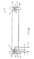
- Figures 6, 7, 9, 10 and 11 show dowel pins 48 extending from the base 40.
- the dowel pins 48 are slidingly disposed in dowel holes 50 in the base and extend into or through dowel holes 51 in the end plates 32.
- Bolts 45d extend through the end plates 32 into holes 53 ( Figure 6) in the base to hold the ring assembly together.
- the dowel pins are tight-fitting in the respective dowel holes, but are preferably slidingly movable therein by pressing or punching the pins with hand tools.
- the dowel holes extend deeply enough into the base that the dowel pins may be pressed or punched into the holes and wholly contained thereby, so that outer ends 49 of the dowel pins may be substantially flush with or beneath an outer end surfaces of the base. Accordingly, if the length of the dowel pins is "L 1 ,” the depth of the dowel holes “L 2 ,” is preferably at least as great as “L 1 .”
- the dowel pins are ordinarily positioned to extend from the dowel holes, into or through the plates 32, to locate the base 40 to the plates 32.
- the dowel pins on at least one end of the knife assembly may be pressed or punched into the dowel holes so that the knife assembly is free to slide radially out of the ring assembly. It is an outstanding advantage of the ring assembly 30 that the knife assembly can be removed from the ring assembly simply by removing the bolts 45d and pressing or punching the dowel pins on at least one end of the knife assembly into their respective dowel holes.
Landscapes
- Engineering & Computer Science (AREA)
- Life Sciences & Earth Sciences (AREA)
- Manufacturing & Machinery (AREA)
- Mechanical Engineering (AREA)
- Wood Science & Technology (AREA)
- Forests & Forestry (AREA)
- Manufacture Of Wood Veneers (AREA)
- Details Of Cutting Devices (AREA)
- Crushing And Pulverization Processes (AREA)
- Disintegrating Or Milling (AREA)
- Surgical Instruments (AREA)
- Measurement Of The Respiration, Hearing Ability, Form, And Blood Characteristics Of Living Organisms (AREA)
- Nonmetal Cutting Devices (AREA)
- Ignition Installations For Internal Combustion Engines (AREA)
- Cable Accessories (AREA)
- Food-Manufacturing Devices (AREA)
- Knives (AREA)
Claims (7)
- Vorrichtung zum Schneiden eines Gegenstands aus Holz, die aufweist:eine Ringanordnung, aufweisend zwei Endplatten (32a, 32b) für eine Drehung um eine Drehachse (2) und eine Mehrzahl von Messeranordnungen (34), wobei jede Anordnung ein langgestrecktes Messer (36), das eine Schneidkante (24a, 24b) besitzt, die sich entlang einer Längsachse erstreckt, ein Basisteil (40) und eine Klammer (39) zum Klemmen des Messers an dem Basisteil aufweist, wobei sich die Anordnungen (34) zur Installation zwischen den Endplatten (32) mit einer oder mehreren Schrauben (45d) durch eine oder beide der Endplatte(n) (32) in die jeweiligen Basisteile erstrecken, wobei die Basisteile eine oder mehrere erste Öffnung(en) umfassen und wobei mindestens eine der Endplatten einen entsprechenden Satz von einer oder mehreren zweiten Öffnung(en) dort hindurch zum Aufnehmen jeweiliger entsprechender Stehbolzen umfasst, dadurch gekennzeichnet, dass die ersten Öffnungen so angepasst sind, um gut gleitend die jeweiligen Stehbolzen (48) innerhalb eines Bereichs, definiert durch eine erste Position, in der sich die jeweiligen Stehbolzen in mindestens eine der Endplatten hinein erstrecken, zu einer zweiten Position, in der die jeweiligen Stehbolzen im Wesentlichen vollständig innerhalb der jeweiligen ersten Öffnungen eingepasst sind, aufzunehmen.
- Vorrichtung nach Anspruch 1, wobei, für jede Messeranordnung (34), die Klammer (38) ein oberes Klemmelement (38a) umfasst, das an dem Basisteil so befestigt ist, dass ein Bereich des oberen Klemmelements von dem Basisteil freitragend ist, und wobei jede Messeranordnung eine Vorkehrung für mindestens eine Schraube umfasst, die sich durch den jeweiligen Bereich in das jeweilige Basisteil hinein erstreckt, wobei ein Festziehen der Schraube elastisch das obere Klemmelement (38a) gegen eine Seite des Messers ablenkt, und ein Lösen der Schraube zulässt, dass sich das obere Klemmelement so entspannt, dass das obere Klemmelement nicht länger einen Kontakt mit der einen Seite des Messers vornimmt.
- Vorrichtung nach einem der Ansprüche 1 bis 2, wobei das Messer zwei gegenüberliegende Schneidkanten besitzt.
- Vorrichtung nach einem der Ansprüche 1 bis 3, wobei beide der Endplatten jeweilige Schlitze umfassen, die den Anordnungen entsprechen, wobei die Schlitze so angepasst sind, um die jeweiligen Messer der Anordnungen durch die Endplatten in der Richtung der Längsachsen zu führen.
- Vorrichtung zum Schneiden eines Gegenstands aus Holz, wobei die Vorrichtung aufweist: eine Ringanordnung, aufweisend zwei Endplatten (32a, 32b) für eine Drehung um eine Drehachse und eine Mehrzahl von Messeranordnungen (34), wobei jede Messeranordnung ein langgestrecktes Messer (36), das eine Schneidkante besitzt, die sich entlang einer Längsachse erstreckt, ein Basisteil (40) und eine Klammer zum Klemmen des Messers an dem Basisteil aufweist, wobei sich die Anordnungen zur Installation zwischen den Endplatten durch eine oder mehrere langgestreckte Befestigungsvorrichtungen durch eine oder beide der Endplatte(n) in die jeweiligen Basisteile hinein erstreckt/erstrecken, wobei die Basisteile eine oder mehrere erste Offnung(en) umfassen und wobei mindestens eine der Endplatten einen entsprechenden Satz von einer oder mehreren zweiten Öffnung(en) dort hindurch zum Aufnehmen jeweiliger entsprechender Stehbolzen umfasst, dadurch gekennzeichnet, dass die Stifte und die ersten Öffnungen für eine zurückhaltende Aufnahme der jeweiligen Stifte (48) in den ersten Öffnungen, um so gleitend verschiebbar zu sein, innerhalb eines Bereichs, definiert durch eine erste Position, in der sich die jeweiligen Stifte in die mindestens eine der Endplatten hinein erstrecken, zu einer zweiten Position, in der die jeweiligen Stifte im Wesentlichen vollständig innerhalb der jeweiligen ersten Öffnungen in den Öffnungen, durch Aufbringen einer axialen Entnahmekraft auf die Stifte, aufgenommen sind, aufgebaut sind.
- Verfahren zum Warten oder Reparieren einer Ringschneidvorrichtung, wobei das Verfahren die Schritte aufweist: Bereitstellen einer Ringanordnung, die zwei Endplatten (32a, 32b) für eine Drehung um eine Achse und eine Mehrzahl von Messeranordnungen (34) aufweist, wobei jede Anordnung ein langgestrecktes Messer (36), das eine Schneidkante besitzt, die sich entlang einer Längsachse erstreckt, ein Basisteil (40) und eine Klammer zum Klemmen des Messers an dem Basisteil aufweist, wobei sich die Anordnungen zur Installation zwischen den Endplatten mit einer oder mehreren Schraube(n) durch eine oder beide der Endplatte(n) in die jeweiligen Basisteile hinein erstrecken, wobei die Basisteile jeweilige erste Öffnung(en) umfassen und wobei eine der Endplatten jeweilige entsprechende zweite Öffnungen zum Aufnehmen jeweiliger Stehbolzen (48) umfasst, wobei eine erste Öffnung entsprechend zu einer ausgewählten einen der Anordnung gut gleitend einen Stehbolzen aufnimmt, der sich auch in eine entsprechende zweite Öffnung in der einen Endplatte hinein erstreckt, um so die ausgewählte Anordnung mit der einen Endplatte zu verbinden, gekennzeichnet durch Drücken des Stehbolzens (48) durch die zweite Öffnung in die erste Öffnung hinein, so dass sich der Stehbolzen nicht länger in die zweite Öffnung hinein erstreckt, um dadurch zu ermöglichen, dass mindestens ein Ende der ausgewählten Anordnung radial von den Endplatten weg in Bezug auf die Drehachse bewegt werden kann.
- Verfahren nach Anspruch 6, und umfassend das Vorsehen, für jede Messeranordnung, dass die Klammer ein oberes Klemmelement, das an dem Basisteil befestigt ist, so dass ein Bereich des oberen Klemmelements frei von dem Basisteil aufgehängt ist, das Vorsehen, dass jede Messeranordnung mindestens eine Schraube umfasst, die sich durch den jeweiligen Bereich in das jeweilige Basisteil hinein erstreckt, und das Festziehen mindestens einer der Schrauben, um elastisch den entsprechenden Bereich gegen eine Seite des entsprechenden Messers abzulenken, um das Messer zu klemmen.
Priority Applications (1)
| Application Number | Priority Date | Filing Date | Title |
|---|---|---|---|
| EP04025964A EP1510308B1 (de) | 2002-10-25 | 2003-10-01 | Messerpaket |
Applications Claiming Priority (2)
| Application Number | Priority Date | Filing Date | Title |
|---|---|---|---|
| US280278 | 2002-10-25 | ||
| US10/280,278 US6757952B1 (en) | 2002-10-25 | 2002-10-25 | Ring slicer with easily removable knife and knife assembly |
Related Child Applications (1)
| Application Number | Title | Priority Date | Filing Date |
|---|---|---|---|
| EP04025964A Division EP1510308B1 (de) | 2002-10-25 | 2003-10-01 | Messerpaket |
Publications (3)
| Publication Number | Publication Date |
|---|---|
| EP1413410A2 EP1413410A2 (de) | 2004-04-28 |
| EP1413410A3 EP1413410A3 (de) | 2004-08-11 |
| EP1413410B1 true EP1413410B1 (de) | 2005-07-06 |
Family
ID=32069370
Family Applications (2)
| Application Number | Title | Priority Date | Filing Date |
|---|---|---|---|
| EP03256191A Expired - Lifetime EP1413410B1 (de) | 2002-10-25 | 2003-10-01 | Zerkleinerungsmachine mit rotierendem Messerkranz |
| EP04025964A Expired - Lifetime EP1510308B1 (de) | 2002-10-25 | 2003-10-01 | Messerpaket |
Family Applications After (1)
| Application Number | Title | Priority Date | Filing Date |
|---|---|---|---|
| EP04025964A Expired - Lifetime EP1510308B1 (de) | 2002-10-25 | 2003-10-01 | Messerpaket |
Country Status (11)
| Country | Link |
|---|---|
| US (1) | US6757952B1 (de) |
| EP (2) | EP1413410B1 (de) |
| AT (2) | ATE299084T1 (de) |
| AU (1) | AU2003248379B2 (de) |
| BR (2) | BR0304048A (de) |
| CA (1) | CA2441632C (de) |
| DE (1) | DE60300970T2 (de) |
| DK (1) | DK1413410T3 (de) |
| ES (2) | ES2242927T3 (de) |
| NZ (1) | NZ528603A (de) |
| PT (1) | PT1413410E (de) |
Families Citing this family (11)
| Publication number | Priority date | Publication date | Assignee | Title |
|---|---|---|---|---|
| US7836923B2 (en) * | 2002-10-25 | 2010-11-23 | Key Knife, Inc. | Ring slicer with easily removable knife and knife assembly |
| DE102004004877A1 (de) * | 2004-01-30 | 2005-08-18 | Pallmann Maschinenfabrik Gmbh & Co Kg | Zerkleinerungsvorrichtung mit Messerring |
| DE202008017494U1 (de) * | 2007-04-23 | 2009-11-26 | Steininger, Werner | Werkzeug zum Zerkleinern von Holz |
| US7891388B2 (en) * | 2007-06-29 | 2011-02-22 | Key Knife, Inc. | Knife and knife assembly for a planer side head |
| US7938155B2 (en) * | 2008-02-29 | 2011-05-10 | Simonds International Corporation | Ring strander knife assembly and method of use |
| AT508095B1 (de) | 2009-03-27 | 2011-01-15 | Eschlboeck Maschb Gmbh | Vorrichtung zum zerkleinern von holz |
| US8176955B2 (en) * | 2009-11-13 | 2012-05-15 | Simonds International Corporation | Disk flaker knife assembly |
| CN103213008B (zh) * | 2013-04-25 | 2016-04-20 | 株洲钻石切削刀具股份有限公司 | 用于加工曲轴外铣刀具刀夹上刀槽的夹具及方法 |
| DE102015005787B4 (de) * | 2015-05-09 | 2018-11-29 | Pallmann Maschinenfabrik Gmbh & Co. Kg | Zerkleinerungseinheit für eine Zerkleinerungsvorrichtung zum Zerkleinern von Aufgabegut, insbesondere Messerkorb |
| CN112549231B (zh) * | 2020-12-24 | 2022-03-22 | 巫溪县渝星建材有限责任公司 | 木材刨花机旋转刀筒及木材刨花机 |
| DE202023104286U1 (de) * | 2023-07-28 | 2023-10-16 | Blank Service Gmbh | Schneideinrichtung zur Verwendung in einem Messerring einer Messerringholzzerspanungsvorrichtung, Messerring sowie Messerringholzzerspanungsvorrichtung |
Family Cites Families (26)
| Publication number | Priority date | Publication date | Assignee | Title |
|---|---|---|---|---|
| DE1214862B (de) * | 1962-03-13 | 1966-04-21 | Ind Companie Kleinewefers Kons | Befestigung von Messereinsatzstuecken in Trommelzerspanern fuer die Herstellung von Holzspaenen |
| GB1071636A (en) * | 1963-03-28 | 1967-06-07 | Amf Internat Ltd | Improvements relating to machines for cutting leaf tobacco |
| DE1653122A1 (de) * | 1967-07-22 | 1971-11-11 | Ludwig Pallmann Maschinenfabri | Zerspanungsmaschinen,insbesondere Holzzerspanungs-Maschinen |
| DE2208687B1 (de) * | 1972-02-24 | 1973-06-14 | Hombak Maschinenfab Kg | Messerwelle für Holzbearbeitungsmaschinen |
| DE2334151A1 (de) * | 1973-07-05 | 1975-01-16 | Pallmann Kg Maschf | Messerring fuer zerspanungsmaschinen, im besonderen fuer holzzerspaner |
| IT1032275B (it) * | 1974-03-13 | 1979-05-30 | Maier Kg Maschf B | Albero portacoltelli per dispositivi truciolatori |
| US4135563A (en) * | 1976-03-15 | 1979-01-23 | Maucher Walter H | Apparatus for reducing fiber material to chip form |
| US4139034A (en) * | 1977-02-15 | 1979-02-13 | Hawker Siddeley Canada Ltd. | Waferizer |
| DE2730800C3 (de) * | 1977-07-07 | 1980-02-21 | Vereinigte Edelstahlwerke Ag (Vew), Wien | Messeranordnung fur eine Schragschnlttmesserwelle einer Holzzerspanungsmaschüie |
| US4972888A (en) * | 1989-11-14 | 1990-11-27 | Acrowood Corporation | Blade-carrying drum assembly for chip slicing machines |
| DE4114840C2 (de) * | 1991-05-07 | 1995-01-19 | Pallmann Kg Maschf | Verfahren und Vorrichtung zum automatischen Auswechseln von nachschleifbaren Messern bei Holzzerspanmaschinen |
| FI90322C (fi) * | 1992-11-18 | 1994-01-25 | Andritz Patentverwaltung | Menetelmä ja laite kiekkohakun terän vaihtamiseksi |
| US5271442B1 (en) * | 1993-02-19 | 1996-05-07 | Commercial Knife Inc | Knife with clamp package mounting knife |
| US5271440A (en) * | 1993-02-24 | 1993-12-21 | Pacific/Hoe Saw And Knife Company | Chipper disc assembly having extended-life regrindable disposable knives |
| AT398403B (de) * | 1993-03-23 | 1994-12-27 | Boehler Ybbstalwerke | Messerwalze und kammesser für messerwellenzerspaner |
| US5348064A (en) * | 1993-09-07 | 1994-09-20 | Carthage Machine Company | Reversible knife holder for chipper |
| US5313696A (en) * | 1993-09-17 | 1994-05-24 | Cae Machinery Ltd. | Method and apparatus for removing blade ring in a ring flaker |
| US5485873A (en) * | 1994-08-09 | 1996-01-23 | Cae Machinery Ltd. | Knife clamping system |
| DE19518354C2 (de) * | 1995-05-19 | 1997-02-27 | Pallmann Kg Maschf | Verfahren und Vorrichtung zum automatischen Auswechseln von kranzförmigen Zerkleinerungswerkzeugen an Zerkleinerungsmaschinen, insbesondere von Messerkränzen für Holzzerspanmaschinen |
| US5819826A (en) * | 1997-10-23 | 1998-10-13 | Key Knife, Inc. | Chip cutting knife with spaced deflector ridges |
| US5996655A (en) * | 1997-12-11 | 1999-12-07 | Cae Machinery Ltd. | Pivoting knife clamp |
| US5937923A (en) | 1998-08-10 | 1999-08-17 | Beloit Technologies, Inc. | Chip slicer |
| US5979522A (en) * | 1998-11-18 | 1999-11-09 | Key Knife, Inc. | Knife holder for a chipper disc |
| DE19921597C1 (de) * | 1999-05-07 | 2000-07-27 | Maier Zerkleinerungsanlage Gmb | Messerring-Zerspaner zum Zerspanen von Hackschnitzeln |
| DE10116691B4 (de) * | 2001-04-04 | 2004-07-15 | Pallmann Maschinenfabrik Gmbh & Co Kg | Vorrichtung zum Zerkleinern von faserigem Aufgabegut, insbesondere Stammholz |
| US6591878B2 (en) * | 2001-07-18 | 2003-07-15 | Key Knife, Inc. | Method and apparatus for clamping a knife |
-
2002
- 2002-10-25 US US10/280,278 patent/US6757952B1/en not_active Expired - Lifetime
-
2003
- 2003-09-24 CA CA002441632A patent/CA2441632C/en not_active Expired - Lifetime
- 2003-09-25 AU AU2003248379A patent/AU2003248379B2/en not_active Expired
- 2003-09-29 NZ NZ528603A patent/NZ528603A/en unknown
- 2003-10-01 DK DK03256191T patent/DK1413410T3/da active
- 2003-10-01 EP EP03256191A patent/EP1413410B1/de not_active Expired - Lifetime
- 2003-10-01 EP EP04025964A patent/EP1510308B1/de not_active Expired - Lifetime
- 2003-10-01 AT AT03256191T patent/ATE299084T1/de not_active IP Right Cessation
- 2003-10-01 PT PT03256191T patent/PT1413410E/pt unknown
- 2003-10-01 DE DE60300970T patent/DE60300970T2/de not_active Expired - Lifetime
- 2003-10-01 ES ES03256191T patent/ES2242927T3/es not_active Expired - Lifetime
- 2003-10-01 AT AT04025964T patent/ATE549141T1/de active
- 2003-10-01 ES ES04025964T patent/ES2382079T3/es not_active Expired - Lifetime
- 2003-10-24 BR BR0304048-8A patent/BR0304048A/pt active IP Right Grant
- 2003-10-24 BR BRPI0304048A patent/BRPI0304048B1/pt unknown
Also Published As
| Publication number | Publication date |
|---|---|
| DE60300970D1 (de) | 2005-08-11 |
| AU2003248379B2 (en) | 2005-08-25 |
| ATE299084T1 (de) | 2005-07-15 |
| CA2441632A1 (en) | 2004-04-12 |
| US6757952B1 (en) | 2004-07-06 |
| BR0304048A (pt) | 2004-09-08 |
| EP1510308A3 (de) | 2005-03-09 |
| CA2441632C (en) | 2005-09-27 |
| ES2382079T3 (es) | 2012-06-05 |
| AU2003248379A1 (en) | 2004-05-13 |
| EP1413410A2 (de) | 2004-04-28 |
| NZ528603A (en) | 2004-05-28 |
| BRPI0304048B1 (pt) | 2019-01-08 |
| DK1413410T3 (da) | 2005-10-31 |
| ATE549141T1 (de) | 2012-03-15 |
| EP1510308A2 (de) | 2005-03-02 |
| DE60300970T2 (de) | 2006-05-18 |
| EP1510308B1 (de) | 2012-03-14 |
| EP1413410A3 (de) | 2004-08-11 |
| ES2242927T3 (es) | 2005-11-16 |
| PT1413410E (pt) | 2005-10-31 |
Similar Documents
| Publication | Publication Date | Title |
|---|---|---|
| EP1413410B1 (de) | Zerkleinerungsmachine mit rotierendem Messerkranz | |
| EP0775043B1 (de) | Klemmsystem für messer | |
| EP1568453B1 (de) | Zerkleinerungsmachine mit rotierendem Messerkranz mit leicht entfernbarem Messer und Messerpaket | |
| US5152469A (en) | Machine for shredding rubber tires and other solid waste material | |
| CA2255427C (en) | Pivoting knife clamp | |
| US5819825A (en) | Interchangeable chipper attachment for a hog | |
| US6293481B1 (en) | Attachment arrangement facilitating rapid replacement of strikers of a wood comminuting rotor | |
| CA2501622C (en) | Ring slicer with easily removable knife and knife assembly | |
| CA2560515C (en) | Ring slicer with easily removable knife and knife assembly | |
| AU2005237118B2 (en) | Ring slicer with easily removable knife and knife assembly | |
| CA2777555C (en) | Clamping apparatus for wood chipper | |
| WO2007081892A1 (en) | Method and apparatus for adjusting knife extension | |
| FI87159C (fi) | Foerfarande och anordning foer byte av kniven i en skivhugg |
Legal Events
| Date | Code | Title | Description |
|---|---|---|---|
| PUAI | Public reference made under article 153(3) epc to a published international application that has entered the european phase |
Free format text: ORIGINAL CODE: 0009012 |
|
| 17P | Request for examination filed |
Effective date: 20031021 |
|
| AK | Designated contracting states |
Kind code of ref document: A2 Designated state(s): AT BE BG CH CY CZ DE DK EE ES FI FR GB GR HU IE IT LI LU MC NL PT RO SE SI SK TR |
|
| AX | Request for extension of the european patent |
Extension state: AL LT LV MK |
|
| PUAL | Search report despatched |
Free format text: ORIGINAL CODE: 0009013 |
|
| AK | Designated contracting states |
Kind code of ref document: A3 Designated state(s): AT BE BG CH CY CZ DE DK EE ES FI FR GB GR HU IE IT LI LU MC NL PT RO SE SI SK TR |
|
| AX | Request for extension of the european patent |
Extension state: AL LT LV MK |
|
| RIC1 | Information provided on ipc code assigned before grant |
Ipc: 7B 23Q 3/155 B Ipc: 7B 27L 11/02 A |
|
| 17Q | First examination report despatched |
Effective date: 20040812 |
|
| GRAP | Despatch of communication of intention to grant a patent |
Free format text: ORIGINAL CODE: EPIDOSNIGR1 |
|
| GRAS | Grant fee paid |
Free format text: ORIGINAL CODE: EPIDOSNIGR3 |
|
| AKX | Designation fees paid |
Designated state(s): AT BE BG CH CY CZ DE DK EE ES FI FR GB GR HU IE IT LI LU MC NL PT RO SE SI SK TR |
|
| GRAA | (expected) grant |
Free format text: ORIGINAL CODE: 0009210 |
|
| AK | Designated contracting states |
Kind code of ref document: B1 Designated state(s): AT BE BG CH CY CZ DE DK EE ES FI FR GB GR HU IE IT LI LU MC NL PT RO SE SI SK TR |
|
| PG25 | Lapsed in a contracting state [announced via postgrant information from national office to epo] |
Ref country code: EE Free format text: LAPSE BECAUSE OF FAILURE TO SUBMIT A TRANSLATION OF THE DESCRIPTION OR TO PAY THE FEE WITHIN THE PRESCRIBED TIME-LIMIT Effective date: 20050706 Ref country code: SK Free format text: LAPSE BECAUSE OF FAILURE TO SUBMIT A TRANSLATION OF THE DESCRIPTION OR TO PAY THE FEE WITHIN THE PRESCRIBED TIME-LIMIT Effective date: 20050706 Ref country code: SI Free format text: LAPSE BECAUSE OF FAILURE TO SUBMIT A TRANSLATION OF THE DESCRIPTION OR TO PAY THE FEE WITHIN THE PRESCRIBED TIME-LIMIT Effective date: 20050706 Ref country code: RO Free format text: LAPSE BECAUSE OF FAILURE TO SUBMIT A TRANSLATION OF THE DESCRIPTION OR TO PAY THE FEE WITHIN THE PRESCRIBED TIME-LIMIT Effective date: 20050706 |
|
| REG | Reference to a national code |
Ref country code: GB Ref legal event code: FG4D |
|
| REG | Reference to a national code |
Ref country code: CH Ref legal event code: EP |
|
| REG | Reference to a national code |
Ref country code: IE Ref legal event code: FG4D |
|
| REF | Corresponds to: |
Ref document number: 60300970 Country of ref document: DE Date of ref document: 20050811 Kind code of ref document: P |
|
| REG | Reference to a national code |
Ref country code: CH Ref legal event code: NV Representative=s name: E. BLUM & CO. PATENTANWAELTE |
|
| PG25 | Lapsed in a contracting state [announced via postgrant information from national office to epo] |
Ref country code: CY Free format text: LAPSE BECAUSE OF FAILURE TO SUBMIT A TRANSLATION OF THE DESCRIPTION OR TO PAY THE FEE WITHIN THE PRESCRIBED TIME-LIMIT Effective date: 20051001 |
|
| PG25 | Lapsed in a contracting state [announced via postgrant information from national office to epo] |
Ref country code: GR Free format text: LAPSE BECAUSE OF FAILURE TO SUBMIT A TRANSLATION OF THE DESCRIPTION OR TO PAY THE FEE WITHIN THE PRESCRIBED TIME-LIMIT Effective date: 20051006 |
|
| REG | Reference to a national code |
Ref country code: SE Ref legal event code: TRGR |
|
| PG25 | Lapsed in a contracting state [announced via postgrant information from national office to epo] |
Ref country code: MC Free format text: LAPSE BECAUSE OF NON-PAYMENT OF DUE FEES Effective date: 20051031 Ref country code: LU Free format text: LAPSE BECAUSE OF NON-PAYMENT OF DUE FEES Effective date: 20051031 |
|
| REG | Reference to a national code |
Ref country code: DK Ref legal event code: T3 Ref country code: PT Ref legal event code: SC4A Effective date: 20050906 |
|
| REG | Reference to a national code |
Ref country code: ES Ref legal event code: FG2A Ref document number: 2242927 Country of ref document: ES Kind code of ref document: T3 |
|
| PG25 | Lapsed in a contracting state [announced via postgrant information from national office to epo] |
Ref country code: HU Free format text: LAPSE BECAUSE OF FAILURE TO SUBMIT A TRANSLATION OF THE DESCRIPTION OR TO PAY THE FEE WITHIN THE PRESCRIBED TIME-LIMIT Effective date: 20060107 |
|
| ET | Fr: translation filed | ||
| PLBE | No opposition filed within time limit |
Free format text: ORIGINAL CODE: 0009261 |
|
| STAA | Information on the status of an ep patent application or granted ep patent |
Free format text: STATUS: NO OPPOSITION FILED WITHIN TIME LIMIT |
|
| 26N | No opposition filed |
Effective date: 20060407 |
|
| REG | Reference to a national code |
Ref country code: CH Ref legal event code: PFA Owner name: KEY KNIFE, INC. Free format text: KEY KNIFE, INC.#19100 S.W. 125TH COURT#TUALATIN, OREGON 97062 (US) -TRANSFER TO- KEY KNIFE, INC.#19100 S.W. 125TH COURT#TUALATIN, OREGON 97062 (US) |
|
| PGFP | Annual fee paid to national office [announced via postgrant information from national office to epo] |
Ref country code: BG Payment date: 20080717 Year of fee payment: 6 Ref country code: CH Payment date: 20080916 Year of fee payment: 6 Ref country code: PT Payment date: 20080716 Year of fee payment: 6 |
|
| PGFP | Annual fee paid to national office [announced via postgrant information from national office to epo] |
Ref country code: CZ Payment date: 20080723 Year of fee payment: 6 Ref country code: IE Payment date: 20080714 Year of fee payment: 6 Ref country code: IT Payment date: 20080923 Year of fee payment: 6 Ref country code: NL Payment date: 20081021 Year of fee payment: 6 |
|
| PGFP | Annual fee paid to national office [announced via postgrant information from national office to epo] |
Ref country code: DK Payment date: 20081027 Year of fee payment: 6 Ref country code: TR Payment date: 20080807 Year of fee payment: 6 |
|
| PGFP | Annual fee paid to national office [announced via postgrant information from national office to epo] |
Ref country code: AT Payment date: 20080827 Year of fee payment: 6 Ref country code: BE Payment date: 20080801 Year of fee payment: 6 Ref country code: FI Payment date: 20081002 Year of fee payment: 6 |
|
| PGFP | Annual fee paid to national office [announced via postgrant information from national office to epo] |
Ref country code: SE Payment date: 20081022 Year of fee payment: 6 |
|
| PGFP | Annual fee paid to national office [announced via postgrant information from national office to epo] |
Ref country code: GB Payment date: 20081009 Year of fee payment: 6 |
|
| BERE | Be: lapsed |
Owner name: *KEY KNIFE INC. Effective date: 20091031 |
|
| REG | Reference to a national code |
Ref country code: NL Ref legal event code: V1 Effective date: 20100501 |
|
| REG | Reference to a national code |
Ref country code: CH Ref legal event code: PL |
|
| EUG | Se: european patent has lapsed | ||
| REG | Reference to a national code |
Ref country code: DK Ref legal event code: EBP |
|
| REG | Reference to a national code |
Ref country code: IE Ref legal event code: MM4A |
|
| PG25 | Lapsed in a contracting state [announced via postgrant information from national office to epo] |
Ref country code: NL Free format text: LAPSE BECAUSE OF NON-PAYMENT OF DUE FEES Effective date: 20100501 Ref country code: PT Free format text: LAPSE BECAUSE OF NON-PAYMENT OF DUE FEES Effective date: 20100401 Ref country code: BG Free format text: FAILURE TO ELECT DOMICILE IN THE NATIONAL COUNTRY Effective date: 20100430 |
|
| PG25 | Lapsed in a contracting state [announced via postgrant information from national office to epo] |
Ref country code: FI Free format text: LAPSE BECAUSE OF NON-PAYMENT OF DUE FEES Effective date: 20091001 Ref country code: CZ Free format text: LAPSE BECAUSE OF NON-PAYMENT OF DUE FEES Effective date: 20091001 Ref country code: AT Free format text: LAPSE BECAUSE OF NON-PAYMENT OF DUE FEES Effective date: 20091001 |
|
| PG25 | Lapsed in a contracting state [announced via postgrant information from national office to epo] |
Ref country code: LI Free format text: LAPSE BECAUSE OF NON-PAYMENT OF DUE FEES Effective date: 20091031 Ref country code: BE Free format text: LAPSE BECAUSE OF NON-PAYMENT OF DUE FEES Effective date: 20091031 Ref country code: IE Free format text: LAPSE BECAUSE OF NON-PAYMENT OF DUE FEES Effective date: 20091001 Ref country code: CH Free format text: LAPSE BECAUSE OF NON-PAYMENT OF DUE FEES Effective date: 20091031 |
|
| PG25 | Lapsed in a contracting state [announced via postgrant information from national office to epo] |
Ref country code: GB Free format text: LAPSE BECAUSE OF NON-PAYMENT OF DUE FEES Effective date: 20091001 |
|
| PG25 | Lapsed in a contracting state [announced via postgrant information from national office to epo] |
Ref country code: DK Free format text: LAPSE BECAUSE OF NON-PAYMENT OF DUE FEES Effective date: 20091031 |
|
| PG25 | Lapsed in a contracting state [announced via postgrant information from national office to epo] |
Ref country code: IT Free format text: LAPSE BECAUSE OF NON-PAYMENT OF DUE FEES Effective date: 20091001 |
|
| PG25 | Lapsed in a contracting state [announced via postgrant information from national office to epo] |
Ref country code: SE Free format text: LAPSE BECAUSE OF NON-PAYMENT OF DUE FEES Effective date: 20091002 |
|
| PG25 | Lapsed in a contracting state [announced via postgrant information from national office to epo] |
Ref country code: TR Free format text: LAPSE BECAUSE OF NON-PAYMENT OF DUE FEES Effective date: 20091001 |
|
| REG | Reference to a national code |
Ref country code: FR Ref legal event code: PLFP Year of fee payment: 13 |
|
| REG | Reference to a national code |
Ref country code: FR Ref legal event code: PLFP Year of fee payment: 14 |
|
| REG | Reference to a national code |
Ref country code: FR Ref legal event code: PLFP Year of fee payment: 15 |
|
| REG | Reference to a national code |
Ref country code: FR Ref legal event code: PLFP Year of fee payment: 16 |
|
| PGFP | Annual fee paid to national office [announced via postgrant information from national office to epo] |
Ref country code: FR Payment date: 20221028 Year of fee payment: 20 |
|
| PGFP | Annual fee paid to national office [announced via postgrant information from national office to epo] |
Ref country code: ES Payment date: 20221128 Year of fee payment: 20 |
|
| PGFP | Annual fee paid to national office [announced via postgrant information from national office to epo] |
Ref country code: DE Payment date: 20221222 Year of fee payment: 20 |
|
| REG | Reference to a national code |
Ref country code: DE Ref legal event code: R071 Ref document number: 60300970 Country of ref document: DE |
|
| REG | Reference to a national code |
Ref country code: ES Ref legal event code: FD2A Effective date: 20231027 |
|
| PG25 | Lapsed in a contracting state [announced via postgrant information from national office to epo] |
Ref country code: ES Free format text: LAPSE BECAUSE OF EXPIRATION OF PROTECTION Effective date: 20231002 |
|
| PG25 | Lapsed in a contracting state [announced via postgrant information from national office to epo] |
Ref country code: ES Free format text: LAPSE BECAUSE OF EXPIRATION OF PROTECTION Effective date: 20231002 |