EP1413530A1 - Maschine zum Bewegen von Behältern vor Prüfungsvorrichtungen - Google Patents
Maschine zum Bewegen von Behältern vor Prüfungsvorrichtungen Download PDFInfo
- Publication number
- EP1413530A1 EP1413530A1 EP03356158A EP03356158A EP1413530A1 EP 1413530 A1 EP1413530 A1 EP 1413530A1 EP 03356158 A EP03356158 A EP 03356158A EP 03356158 A EP03356158 A EP 03356158A EP 1413530 A1 EP1413530 A1 EP 1413530A1
- Authority
- EP
- European Patent Office
- Prior art keywords
- carriage
- machine according
- frame
- machine
- movable panel
- Prior art date
- Legal status (The legal status is an assumption and is not a legal conclusion. Google has not performed a legal analysis and makes no representation as to the accuracy of the status listed.)
- Granted
Links
Images



Classifications
-
- B—PERFORMING OPERATIONS; TRANSPORTING
- B65—CONVEYING; PACKING; STORING; HANDLING THIN OR FILAMENTARY MATERIAL
- B65G—TRANSPORT OR STORAGE DEVICES, e.g. CONVEYORS FOR LOADING OR TIPPING, SHOP CONVEYOR SYSTEMS OR PNEUMATIC TUBE CONVEYORS
- B65G21/00—Supporting or protective framework or housings for endless load-carriers or traction elements of belt or chain conveyors
- B65G21/10—Supporting or protective framework or housings for endless load-carriers or traction elements of belt or chain conveyors movable, or having interchangeable or relatively movable parts; Devices for moving framework or parts thereof
-
- B—PERFORMING OPERATIONS; TRANSPORTING
- B65—CONVEYING; PACKING; STORING; HANDLING THIN OR FILAMENTARY MATERIAL
- B65G—TRANSPORT OR STORAGE DEVICES, e.g. CONVEYORS FOR LOADING OR TIPPING, SHOP CONVEYOR SYSTEMS OR PNEUMATIC TUBE CONVEYORS
- B65G15/00—Conveyors having endless load-conveying surfaces, i.e. belts and like continuous members, to which tractive effort is transmitted by means other than endless driving elements of similar configuration
- B65G15/10—Conveyors having endless load-conveying surfaces, i.e. belts and like continuous members, to which tractive effort is transmitted by means other than endless driving elements of similar configuration comprising two or more co-operating endless surfaces with parallel longitudinal axes, or a multiplicity of parallel elements, e.g. ropes defining an endless surface
- B65G15/12—Conveyors having endless load-conveying surfaces, i.e. belts and like continuous members, to which tractive effort is transmitted by means other than endless driving elements of similar configuration comprising two or more co-operating endless surfaces with parallel longitudinal axes, or a multiplicity of parallel elements, e.g. ropes defining an endless surface with two or more endless belts
- B65G15/14—Conveyors having endless load-conveying surfaces, i.e. belts and like continuous members, to which tractive effort is transmitted by means other than endless driving elements of similar configuration comprising two or more co-operating endless surfaces with parallel longitudinal axes, or a multiplicity of parallel elements, e.g. ropes defining an endless surface with two or more endless belts the load being conveyed between the belts
-
- G—PHYSICS
- G01—MEASURING; TESTING
- G01N—INVESTIGATING OR ANALYSING MATERIALS BY DETERMINING THEIR CHEMICAL OR PHYSICAL PROPERTIES
- G01N33/00—Investigating or analysing materials by specific methods not covered by groups G01N1/00 - G01N31/00
- G01N33/0078—Testing material properties on manufactured objects
- G01N33/0081—Containers; Packages; Bottles
-
- G—PHYSICS
- G01—MEASURING; TESTING
- G01N—INVESTIGATING OR ANALYSING MATERIALS BY DETERMINING THEIR CHEMICAL OR PHYSICAL PROPERTIES
- G01N21/00—Investigating or analysing materials by the use of optical means, i.e. using sub-millimetre waves, infrared, visible or ultraviolet light
- G01N21/84—Systems specially adapted for particular applications
- G01N21/88—Investigating the presence of flaws or contamination
- G01N21/90—Investigating the presence of flaws or contamination in a container or its contents
-
- G—PHYSICS
- G01—MEASURING; TESTING
- G01N—INVESTIGATING OR ANALYSING MATERIALS BY DETERMINING THEIR CHEMICAL OR PHYSICAL PROPERTIES
- G01N21/00—Investigating or analysing materials by the use of optical means, i.e. using sub-millimetre waves, infrared, visible or ultraviolet light
- G01N21/84—Systems specially adapted for particular applications
- G01N21/88—Investigating the presence of flaws or contamination
- G01N21/90—Investigating the presence of flaws or contamination in a container or its contents
- G01N21/9009—Non-optical constructional details affecting optical inspection, e.g. cleaning mechanisms for optical parts, vibration reduction
Definitions
- the present invention relates to the technical field of machines ensuring the movement of containers in front of at least one and, in general, a series of control stations and / or inspection containers.
- the present invention finds a particularly advantageous application in the field of control or inspection of transparent or translucent containers, such as, for example, bottles, jars or bottles made of glass.
- a machine running the containers in front of different checkpoints generally comprises a frame equipped with an endless belt drive system mounted opposite one another to define, between them, a path for gripping and moving the containers from one end to the other of the belts.
- the latter pass successively in front of various checkpoints and / or inspection, generally optical, carried by the frame.
- the belts are mounted movable spacing / approximation to allow to adjust the width of the path of gripping and movement of the containers.
- such a machine is integrated on a conveying path of the containers forming part of a manufacturing and / or packaging line.
- the conveyor must be interrupted to allow the interposition of a moving machine and control, as described above.
- the industrial and especially economic constraints require to realize a machine of displacement and control having a congestion as limited as possible, while integrating a maximum of stations of detection.
- the means used to ensure the movement of containers of various sizes have a significant footprint, which limits the number of control stations that can be installed or leads to the presence of a large number of mechanical equipment , electric and optical in a small space. This congestion makes it difficult, in particular, repair, maintenance or cleaning operations, for example when broken containers contaminate the various components of the machine.
- Such a machine comprises a deflection conveyor, shaped so as to drive the containers from the first scroll section to the second multi-trajectory scroll section.
- This diverting conveyor is designed to allow the containers to move in a suspended manner, without resting on their bottom.
- Such a deflection conveyor is mounted in parallel with the main conveyor so that the containers undergo a non-linear trajectory, which limits the speed of movement of the containers and complicates the handling of non-cylindrical containers.
- Such a machine is therefore not suitable for being interposed on a conveyor path forming part of a production line and / or packaging.
- the object of the invention is therefore to overcome the drawbacks stated above by providing a compact machine, intended to be integrated on a conveyor line, while allowing to move containers of various sizes in front of a series of stations. detection and / or control.
- Another object of the invention is to provide a machine designed to facilitate access to the environment of the container movement zone.
- each half-carriage comprises a geared motor mounted in the axis of the motorized drive member.
- Another object of the invention is to propose a machine comprising a protective covering and an access door allowing an operator to use the man-machine interface, both in the open and closed position of the door.
- the means for moving the receiving structure consist of the displacement guiding means which ensure the sliding and pivoting of the movable panel ensuring that in the open position of the movable panel the front of the panel mobile is facing the bay.
- the means for moving the receiving structure are constituted by pivoting means of the man-machine interface ensuring that the front of the man-machine interface is accessible in the closed position and in the position opening of the mobile panel.
- Fig. 1 is a perspective view of a machine according to the invention in the closed door position.
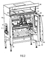
- Fig. 2 is a view similar to FIG. 1 but illustrated with the door in the open position.
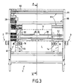
- Fig. 3 is a front elevational view of a machine according to the invention without a door.
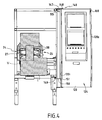
- Fig. 4 is a cross-sectional elevation view taken substantially along lines AA of FIG. 3, of the machine equipped with a door in open position.
- Fig. 5 is a perspective view of the lower frame forming part of the machine according to the invention.
- Fig. 6 is a perspective view of the mobile carriage forming part of the machine according to the invention.
- Fig. 7 is a cross-sectional view of the movable carriage shown in FIG. 6.
- Fig. 8 is a fragmentary detail view showing the characteristics of the machine according to the invention.
- Figs. 9 and 10 are schematic views of another embodiment of mounting on a machine a door having a movable panel.
- each control and / or inspection station comprises, as constituent elements, supports, sensors, light sources, etc.
- the control and / or inspection stations are not described more precisely because they are not part of the invention and are well known to those skilled in the art.
- This machine 1 is intended to be inserted on a conveyor line of containers, so that it appears, upstream of the machine 1 , a conveyor 2 for supplying the containers to the machine 1 and, downstream, a conveyor 3 evacuation of containers from the machine 1 .
- the machine 1 according to the invention assures the management of the receptacles brought by the conveyor 2 and the displacement of the receptacles to the evacuation conveyor 3 .
- the machine according to the invention comprises a lower frame 5 delimiting a carrier frame 6 having two longitudinal sides 7 and two transverse sides 8 , in consideration of the plane of travel D containers.
- the support frame 6 is equipped with four feet 9 advantageously adjustable in height by any known means.
- the transverse sides 8 are adjustable in length, so that the machine 1 has an adjustable depth.
- the transverse sides 8 are made by telescopic elements.
- Each transverse side 8 has a passage window 11, 12 for the end of a conveyor, respectively supply 2 and discharge 3 of the containers which are only shown schematically in FIG. 3 .
- Each conveyor 2 supply and discharge 3 is intended to cooperate with a return head respectively upstream 13 and downstream 14 , mounted on the lower frame 5 .
- each conveyor 2, 3 is produced by means of an endless conveyor belt mounted on a pulley 16 forming part of a return head 13, 14 .
- Each pulley 16 is mounted on a yoke 17 carried by a transverse side 8 of the lower frame 5 .
- the lower frame 5 delimits, from each transverse side 8 , a passage window 11, 12 , that is to say a volume to allow the mounting of a return head 13, 14 and the passage of a conveyor 2, 3 and containers carried by the conveyors.
- the return heads 13, 14 delimit between them a conveyor interruption volume V , that is to say between the conveyors 2, 3 forming the conveying path.
- This conveyor interruption volume V has a width extending between the two return heads 13, 14 , a depth extending according to a measurement allowing the passage of a container of largest diameter and height s extending according to a measure allowing the passage of a container having a greater height.
- each transverse side 8 is provided with a linear guide system 21 extending outside the conveyor interruption volume V.
- the guide systems 21 are formed, in the illustrated example, by linear guide rails mounted parallel to each other in a direction transverse to the plane of travel D of the containers passing through the return heads 13 and 14 of the conveyors 2, 3 .
- the machine according to the invention comprises, as illustrated in FIG. 6 a movable carriage 23 supported by the linear guide rails 21.
- the movable carriage 23 is composed of a front half-carriage 24 and a rear half-carriage 25 in consideration of the front and rear of the machine 1.
- the half-carriages 24, 25 are symmetrical with respect to the plane of travel D.
- Each half-carriage 24, 25 comprises a rigid bridge 26 mounted at each end, sliding on the linear guide rails 21 .
- Each rigid bridge 26 of the half-carriages 24, 25 extends in a longitudinal extension plane E which is parallel to the plane of travel D of the bottles ( FIG 7 ).
- each rigid bridge 26 is formed of a horizontal beam 27 supported at an upstream end by a support arm, said upstream, 28 and at a downstream end by a support arm, said downstream, 29 .
- Each support arm 28, 29 is provided with a means of cooperation with the linear guide system 21 , such as a sliding shoe 31 cooperating with a linear guide rail 21 .
- each support arm 28, 29 is constituted by a bracket having a vertical branch 32 connected to the horizontal beam 27 and a horizontal branch 33 .
- the horizontal branches 33 of the same rigid bridge 26 are mounted head to tail while being turned towards the transverse side 8 adjacent to the lower frame 5 .
- Each rigid bridge 26 consisting of a horizontal beam 27 extended at each end by a bracket thus has a general shape of omega.
- each rigid bridge 26 is equipped at each support arm 28, 29 , with an amount 34 connected to the end of the horizontal branch 33 opposite that provided with the vertical branch 32 .
- Each upright 34 which rises vertically substantially parallel to a vertical leg 32 is provided at its base with a sliding pad 31.
- each upright 34 of the front half-carriage 24 mounted opposite an upright 34 of the rear half-carriage 25 are mounted at a distance from one another and delimit between them a portion of the cross-section. cross-section of the passage window 11, 12 .
- This portion of the passage window 11, 12 extends over a length substantially equal to that defined by the branches horizontal 33 so as to constitute a mounting volume for a return head 13, 14 .
- Each half-trolley 24, 25 also comprises a motor member 37 for rotating for at least one and, in the illustrated example, two endless belts 38.
- Each drive motor member 37 is supported by the bridge rigid 26 being located at a first end, namely, in the example shown, the upstream end of said bridge 26 , so that the motorized members 37 are located outside the conveyor interruption volume V.
- each half-carriage 24, 25 comprises a geared motor 39 , mounted in the axis of the motorized drive member 37 preferably constituted by a drum or a common drive cake for two endless belts 38 .
- Each drive drum 37 therefore extends in the extension of a geared motor 39 , which limits their bulk.
- the motorized drive members 37 are mounted in the volume delimited by and between the brackets of the upstream support arms 38 . More specifically, each drive drum 37 extends substantially in the extension of a post 34 on the height substantially of the vertical leg 32 of a support arm 28 , each geared motor 39 mounted in the extension of a driving drum 37 projecting from the vertical leg 32 of the support arm 28 . It should be noted that the endless belts 38 extend over a limited length superimposed with the upstream conveyor 2 , so that the containers conveyed by the conveyor 2 can be taken over by the belts 38 .
- Each half-carriage 24, 25 also comprises at least one and, in the illustrated example, two return members 41 each for an endless belt 38 .
- the return members 41 of each half-carriage are supported by the rigid bridge 26 of said carriage, being located at the downstream end of said bridge, opposite the upstream end equipped with the driving drum 37 , so that the organs 41 are located outside the conveyor interruption volume V.
- each return member 41 is constituted by a return pulley.
- the return members 41 are mounted in the volume delimited by and between the brackets of the downstream support arms 29 .
- the return pulleys 41 are therefore located substantially vertically above the surface generated by the horizontal branches 33 of the downstream support arms.
- the endless belts 38 therefore extend on a limited length superimposed with the downstream conveyor 3 , so that the containers moved by the endless belts 38 are taken up, at the level of the return members 41 , by the evacuation conveyor 3 .
- the axis of the return heads 13, 14 of the conveyors 2, 3 are thus situated at the same level or, preferably, within the interval delimited by the axis of the motorized displacement member 37 and the axis of the pulley 41 .
- the containers are thus made to move between the motorized movement member 37 and the return pulleys 41 in a direction of movement represented by the arrow F 1 .
- the direction of movement of the containers can be in the opposite direction to that shown (by making a machine symmetrical to that described).
- Each half-carriage 24, 25 thus comprises at least one and, in the illustrated example, two endless belts 38 each mounted between the motorized drive member 37 and a return pulley 41 .
- the two strands of each endless belt 38 extend on either side of the rigid bridge 26, that is to say more precisely of the beam 27 and the vertical leg 32 of each arm of support 28, 29 .
- Each endless belt 38 therefore surrounds a rigid bridge 26 supported at its base by the lower frame 5 so that each endless belt 38 can be put in place or removed from the motorized drive member 37 and the control member. 41 from the upper part of the half-carriages 24, 25 .
- Each endless belt 38 of a half-carriage has a strand extending at a distance from one end of an endless belt 38 carried by the other half-carriage, so as to delimit between them a path 43 of gripping and moving the containers.
- Each half-carriage 24, 25 is equipped with at least one and, in the illustrated example, with two support strips 47, each extending at the rear of a strand of a belt 38 , and between the motorized drive member 37 and a return pulley 41 , so as to define the gripping path 43 .
- each support strip 47 is provided at its end with a pulley 41 and is mounted on at least one and, preferably, two guide rails 49 being established in a vertical direction and carried by the rigid bridge 26 .
- Each support strip 47 is controlled in vertical translation on the slides 49 by means of a control member 50 making it possible to adjust in height each endless belt 38 .
- Such an adjustment makes it possible to better position the belts on the containers as a function of their shape and / or size.
- each support strip 47 is moved by a manual control 50 acting on a screw-nut type system.
- each motorized drive member 37 associated with a geared motor 39 constitutes a crew slidably mounted on the rigid bridge in a direction substantially parallel to that of scroll F 1 to allow the assembly and disassembly of the belts endless 38.
- Each motorized drive member 37 is provided with a support and guide bearing 52 which also supports the geared motor 39 .
- Such a bearing support and guide 52 is provided with a slider 53 adapted to translate within a guide 54 carried by the upper end of the vertical branch 32 of the upstream support arm 28 .
- Such a moving assembly is locked in position by means of a system 56 for tensioning the belts and locking the crew in the extended position of the belts.
- the tension and locking system of the moving equipment is of the knee type.
- each return member 41 is mounted on a support strip 47 by means of a system 57 for tensioning an endless belt 38 .
- Such a tensioning system 57 can be made by a spring-type system for accommodating the length variations of the endless belts 38 .
- the machine 1 also comprises a displacement system 61 spaced-approximation of a half-carriage 24 relative to the other half-carriage 25 .
- a displacement system 61 is located outside the conveyor interruption volume V to allow free access to said volume.
- the displacement system 61 is constituted by a double screw-nut system each mounted between the adjacent ends of the two rigid bridges 26 of the two half-carriages 24, 25 .
- each screw-nut system comprises a rod 63 threaded at least in part to cooperate with a first nut 64 mounted in each upright 34 of the support arm of the front half-carriage 24 and with a second nut 65 mounted in each upright 34 of support arm of the rear half-carriage 25 .
- the nuts 65 fitted to the rear half-carriage 25 , have a reverse direction thread to that of the nuts 64 of the front half-carriage 24 , so that the rotation of the threaded rods 63 , in a direction or an opposite direction, causes the approximation or the relative spacing of the two half-carriages.
- the threaded rods 63 extend in the volume of the wickets passage 11, 12 , without hindering the movement of the containers, to the extent that the threaded rods 63 are interposed between the strands of the conveyors 2, 3 .
- the movement of the two threaded rods 63 is synchronized via a transmission 66 , for example chain, extending parallel to the longitudinal extension plane E.
- the transmission 66 is constituted by a chain 67 meshing with two pinions 68 fixed on the ends of each threaded rod 63 protruding from the rigid bridge 26 of the rear half-carriage 25.
- One of the threaded rods 63 is provided with a rotational control member 69 , such as, for example, a crank which, thanks to the transmission 66 , allows the simultaneous rotation of the two threaded rods 63 .
- the displacement / reconciliation system 61 ensures the simultaneous and identical movement between the two half-carriages 24, 25 remaining centered with respect to the plane of displacement D extending in the middle of the gripping path and displacement 43 of the containers.
- the movement system in spacing / approximation 61 ensures the displacement of one of the half-carriages relative to the other maintained in a fixed position.
- each screw-nut system is provided with a device for selecting the mode of movement of the half-carriages between them, namely a displacement centered or off-center with respect to the plane of displacement D.
- Such a selection device ensures a disengagement of a half-carriage with respect to the threaded control rods 63 .
- the nuts of a half-carriage for example rear, are provided with an axis of attachment to the amount 34 .
- This fastening pin is removable allowing the nuts to be mounted crazy. Upon removal of these fastening pins, the rotation of the threaded rods 63 control drives the crazy rotation of the nuts, so that the corresponding half-carriage is not moved.
- the lower frame 5 is equipped with a longitudinal support plate 80 slidably mounted on two crosspieces 81 carried by longitudinal sides of the frame and extending parallel to the transverse sides 8 .
- the plate 80 which extends away from the rigid bridges 26 , is intended to support elements forming part of control and / or inspection stations of the containers supported by the endless belts 38 .
- Such elements can be constituted for example by supports, sources lighting, optical sensors, etc.
- the sliding assembly of this support plate 80 makes it possible to ensure the complete displacement of all the members supported by it.
- this support plate 80 is equipped with means enabling it to be locked in position on the sleepers 81 .
- the support plate 80 is connected to a curtain, shutter or carpet (not shown) wound on a drum mounted on the rear longitudinal side 7 of the frame. It should be understood that the curtain constitutes, between the rear longitudinal side and the support plate 80 , a receiving mat or channel for various objects likely to fall from the machine, such as glass debris for example.
- the machine 1 comprises an upper frame 90 carried by the lower frame 5 and constituted by four uprights 91 resting on the lower frame 6 of the lower frame 5 .
- the four uprights 91 are connected at the top by a frame 92 designed to support a storage compartment 93 provided on the front of an access door 95 .
- a compartment 93 is adapted to receive all the electrical and electronic equipment necessary for the operation of the machine and control stations Pi .
- the two rear uprights 91 support one or two longitudinal rear beams 97 , extending horizontally and intended to support elements forming part of the inspection and / or inspection rooms Pi .
- these support beams 97 are mounted on the upper frame 90 by means of transverse slides ensuring their spacing / approximation relative to the longitudinal extension plane E.
- the machine 1 has a reduced bulk, while having a free space around the conveyor interruption volume V , and represented, by way of illustration, by the reference L fig. 3 and 4. It should therefore be understood that the structure of the machine 1 is designed to facilitate access around the conveyor interruption volume V , so as to be able to place the maximum number of checkpoints and / or Pi inspection. It is apparent from the drawings that this machine 1 has a maximum of free space L around the conveyor interruption volume V , while ensuring its function of taking care of and moving the containers.
- the machine 1 preferably comprises a protective covering 100 and an access door 101 .
- the protective covering 100 consists of side panels 102 and 103 carried by the transverse sides 8 of the lower 5 and upper frames 90 in which are arranged openings corresponding to the passage window 11, 12 for the supply conveyors 2 and evacuation 3 and the containers.
- the protective covering 100 also comprises a series of bottom panels 104 covering the rear face of the machine.
- the machine 1 has, also in front, a frame 110 defining a bay 111 to access the machine. This bay 111 is opened or closed using a door 101 according to the invention associated in the example shown to a pivoting leaf 112 .
- the door 101 includes a first movable panel 120 mounted hinged to a second movable panel 121 .
- the first movable panel 120 comprises a receiving structure 122 for control and / or control means 123 of the machine.
- control and / or control means 123 which constitute a man-machine interface are in the form of a keyboard, a screen, a control panel, a mouse, etc.
- This man-machine interface 123 has a facade that is accessible from the front 124 of the first movable panel 120 when the latter occupies its closed position of the bay.
- the first movable panel 120 preferably has a thickness adapted to allow the mounting of the control and / or control means 123 .
- the first movable panel 120 has a bottom wall 125 in front of which is established remotely the front wall 124 in which is arranged at least one housing 127 defined by cheeks 128 connected to a flat wall 129 .
- the bottom wall 125 is connected to the front wall 124 by means of two external flanks 131 , so that the first movable panel 120 constitutes a closed box in the thickness of which the man-machine interface 123 is mounted.
- the frame 110 is equipped with moving guide means 140 for the movable panels 120, 121 , so as to ensure the displacement of the movable panels between a closed position in which the facade 124 of the first mobile panel 120 closes, at less in part, the bay (Fig. 1) and an open position in which the movable panels 120, 121 extend laterally with respect to the bay 111.
- the mobile panel 120 comprises means for moving the receiving structure 122 , adapted to ensure that, in the open position of the mobile panel, the front of the human-machine interface 123 is facing the bay to allow an operator placed in front of the bay 111 , to access the bay and simultaneously the man-machine interface 123 . It must therefore be considered that in the closed position of the door, an operator can access control means 123 and control thereof without cluttering the surrounding space of the machine 1. In the open position of the bay 111 , an operator placed in front of the bay can access the control and / or control means 123 while viewing, without changing places, the interior of the machine in order to simultaneously observe for example the result of the commands made on the human-machine interface 123 .
- the access to the bay 111 is not limited, except by the thickness of the movable panels 120, 121 .
- the moving means of the receiving structure 122 consist of the moving guide means 140 of the movable panel which ensure the sliding panel is slidably pivoted 120 in such a way that opening position of the movable panel, the facade 124 of the movable panel is turned towards the bay 111.
- the sliding guide means and pivoting 140 are constituted by at least one rail 145 for support and guidance mounted on the longitudinal side before 90 1 of the upper frame 90.
- a rail 145, said upper, has a cross section in the shape of "C" and serves as a guide support for a rolling member 146 , such as a roller.
- This rolling member 146 is connected to a tab 147 mounted around a pivot 148, in the upper part of the first movable panel 120, at its free vertical side 120 1 .
- the first movable panel 120 is also equipped with a guide member 149 supported by a lug 150, mounted on a pivot 151, in the lower part of the first movable panel 120, at its free vertical side 120 1 .
- the guide member 149 is mounted inside a rail 153, said lower, supported by a longitudinal side 7 of the lower frame 5 and having a transverse cross-section "U".
- the first movable panel 120 is thus suspended from the upper rail 145 whereas the lower rail 153, cooperating with the guide member 149 prevents rotation of the first movable panel 120.
- it may be envisaged to invert the position between the rolling members 146 and guide 149 or to use two rolling members to support and guide the first movable panel 120 .
- the first movable panel 120 is hinged, at its vertical side 120 2, opposite to the free vertical side 120 1 by hinges 160 on one side of the second movable panel 121 which is also pivotally mounted on the frame 110 along its side opposed by axes 161 .
- the second movable panel 121 is mounted articulated, on one side, to the frame 110 in a vertical direction passing through the axes 161 and, on the other side, to the first movable panel 120 also according to a vertical direction passing through the hinges 160 .
- the movable panels 120 and 121 allow in the deployed position to close the bay. In this position, the front walls of the panels 120, 121 are established in the extension of one another with their side facing outwards with respect to the machine.
- the door 101 is opened by making a tensile force on at least one handle 164 placed for example on the second movable panel 121 , so as to ensure folding between the two movable panels 120 , 121 , so that the first movable panel 120 is folded against the second movable panel with their inner faces or bottom faces towards one another.
- the movable panels 120, 121 extend substantially perpendicularly to the bay with the first movable panel 120 having its facade 124 turned or oriented towards the bay 111 .
- the passage of the door, from its open position to its closed position, is performed in an inverse manner by operating, for example, a tensile force on the first movable panel 120 from a handle 164 to cause it to move. along the guide rails 145, 153.
- Figs. 9 and 10 illustrate another alternative embodiment of sliding and pivoting guide means 140 for an access door 101 having a single movable panel 120 .
- the guide means 140 consist of at least one and, preferably, two support and guide rails 145, 153 , as previously described, for 146, 149 mounted on pivots 170 to a vertical side 120 1 of the movable panel 120.
- the other vertical side 120 2 of the movable panel 120 is connected, at its upper part and at its lower part, by pivots 176, with two extension bars 175 each guided in translation in a slide 178 mounted in a direction substantially perpendicular to the bay 111 .
- a tensile force on the movable panel 120 causes the rolling members 146, 149 to slide along the rails 145, 153 , while simultaneously causing the extension bar 175 to be released to allow the pivoting of the movable panel 120 , way, at the end of the race, to be established substantially perpendicular to the bay 111 .
- the closure of the bay 111 is made in a reverse movement of the movable panel 120 .
- the displacement means of the receiving structure 122 are constituted by the displacement guiding means of the door, which enable the man-machine interface 123 to be positioned so that its facade is accessible both in the open position and in the closed position of the door.
- the means for moving the receiving structure 122 may be constituted by pivoting means of the receiving structure 122 so that the front of the man-machine interface 123 is accessible in the closed position and in the opening position of the movable panel.
- these pivotal means allow to bring, in the open position of the movable panel, the façade of the man-machine interface 123, the back of the movable panel 120 so that it is facing the bay 111 .
- the displacement guiding means are adapted to bring, in the open position, the front of the man-machine interface 123 into a position allowing access to the rack 111 and the man-machine interface 123 .
- the movable panel 120 In the open position, the movable panel 120 is located laterally or on the side of the bay 111 .
- the displacement guiding means allow when the movable panel 120 is in the open position that the front of the man-machine interface 123 extends in a plane substantially perpendicular to the plane defined by the bay 111 .
- these displacement means allow the front of the man-machine interface 123 to extend, in the open position of the mobile panel, into a plane forming with the plane defined by the bay 111, an angle of between 40 ° and 135 ° and preferably between 60 and 110 °.
- the movable panel 120 is locked in its open and closed positions by any appropriate means.
Landscapes
- Engineering & Computer Science (AREA)
- Mechanical Engineering (AREA)
- Health & Medical Sciences (AREA)
- Life Sciences & Earth Sciences (AREA)
- Chemical & Material Sciences (AREA)
- Analytical Chemistry (AREA)
- Immunology (AREA)
- Physics & Mathematics (AREA)
- Food Science & Technology (AREA)
- Biochemistry (AREA)
- General Health & Medical Sciences (AREA)
- General Physics & Mathematics (AREA)
- Medicinal Chemistry (AREA)
- Pathology (AREA)
- Specific Conveyance Elements (AREA)
- Branching, Merging, And Special Transfer Between Conveyors (AREA)
- Power-Operated Mechanisms For Wings (AREA)
- Control Of Conveyors (AREA)
- Intermediate Stations On Conveyors (AREA)
Applications Claiming Priority (2)
| Application Number | Priority Date | Filing Date | Title |
|---|---|---|---|
| FR0213360 | 2002-10-25 | ||
| FR0213360A FR2846314B1 (fr) | 2002-10-25 | 2002-10-25 | Machine de deplacement de recipients devant des postes de controle |
Publications (2)
| Publication Number | Publication Date |
|---|---|
| EP1413530A1 true EP1413530A1 (de) | 2004-04-28 |
| EP1413530B1 EP1413530B1 (de) | 2019-02-13 |
Family
ID=32050672
Family Applications (1)
| Application Number | Title | Priority Date | Filing Date |
|---|---|---|---|
| EP03356158.0A Expired - Lifetime EP1413530B1 (de) | 2002-10-25 | 2003-10-20 | Maschine zum Bewegen von Behältern vor Prüfungsvorrichtungen |
Country Status (7)
| Country | Link |
|---|---|
| US (1) | US7044707B2 (de) |
| EP (1) | EP1413530B1 (de) |
| CN (1) | CN100509587C (de) |
| CA (1) | CA2444995A1 (de) |
| ES (1) | ES2721801T3 (de) |
| FR (1) | FR2846314B1 (de) |
| MX (1) | MXPA03009819A (de) |
Cited By (4)
| Publication number | Priority date | Publication date | Assignee | Title |
|---|---|---|---|---|
| WO2008014962A1 (de) * | 2006-07-31 | 2008-02-07 | Interglarion Limited | Vorrichtung zum herstellen oder/und bearbeiten von paneelen |
| CN109230306A (zh) * | 2018-07-02 | 2019-01-18 | 苏州工业园区耐斯达自动化技术有限公司 | 一种间距可调型轻载传输机构 |
| WO2019029927A1 (de) * | 2017-08-09 | 2019-02-14 | Krones Ag | Rahmen zum befestigen von inspektionsmodulen für behälter und inspektionseinrichtung |
| CN112456026A (zh) * | 2020-12-04 | 2021-03-09 | 郴州市远利机械设备制造有限公司 | 一种钢管加工用传输装置 |
Families Citing this family (27)
| Publication number | Priority date | Publication date | Assignee | Title |
|---|---|---|---|---|
| US20090101068A1 (en) * | 2004-11-15 | 2009-04-23 | Vmi Epe Holland Bv | Roll Coater Assembly System |
| DE102006035648A1 (de) * | 2006-07-31 | 2008-02-07 | Kaindl Flooring Gmbh | Vorrichtung zum Herstellen oder/und Bearbeiten von Paneelen |
| DE102006045107B4 (de) * | 2006-09-21 | 2015-03-12 | Optima Nonwovens Gmbh | Reversierende Vorschubeinrichtung zum taktweisen linearen Vorschieben von Gutstapeln über eine Transportstrecke |
| WO2008121998A1 (en) * | 2007-03-29 | 2008-10-09 | Vmi Holland B.V. | Spindle spray coating system |
| DE102007041251A1 (de) * | 2007-08-30 | 2009-03-05 | Khs Ag | Herstellverfahren für Maschinen |
| CN102807087A (zh) * | 2012-08-21 | 2012-12-05 | 上海港申化工有限公司 | 一种搓盖机用夹瓶装置 |
| CN102897539B (zh) * | 2012-10-17 | 2015-01-28 | 深圳市华星光电技术有限公司 | 一种堆垛机 |
| CN103332435B (zh) * | 2013-06-21 | 2016-04-13 | 杭州中亚机械股份有限公司 | 一种输送装置 |
| CN103738662A (zh) * | 2013-12-04 | 2014-04-23 | 无锡佳泰科技有限公司 | 一种卷装保鲜袋包装输送装置 |
| CN105174174A (zh) * | 2014-06-09 | 2015-12-23 | 慎重光 | 双线路式化妆品加料装置 |
| ES2744927T3 (es) * | 2014-07-23 | 2020-02-26 | Corob Spa | Aparato para mover recipientes |
| CN104495236A (zh) * | 2014-12-18 | 2015-04-08 | 佛山市源田床具机械有限公司 | 袋装弹簧带的摆送装置 |
| CN105523363A (zh) * | 2015-12-07 | 2016-04-27 | 无锡拓能自动化科技有限公司 | 一种用于漏液检测装置的推送装置 |
| DE102016114604A1 (de) * | 2016-08-05 | 2018-02-08 | Wipotec Wiege- Und Positioniersysteme Gmbh | Fördersystem |
| CN106809781A (zh) * | 2017-04-13 | 2017-06-09 | 江苏汤姆森机械有限公司 | 一种全自动跟随式旋盖机 |
| CN109094879B (zh) * | 2018-08-27 | 2020-07-31 | 扬中市惠丰包装有限公司 | 一种传送式储袋供袋装置 |
| FR3092099B1 (fr) | 2019-01-24 | 2021-01-29 | Tiama | Procédé et dispositif de convoyage de récipients en position suspendue |
| WO2020178758A1 (en) * | 2019-03-05 | 2020-09-10 | Sacmi Cooperativa Meccanici Imola Societa' Cooperativa | Apparatus and method for inspecting an object |
| FR3095506B1 (fr) | 2019-04-29 | 2021-05-07 | Tiama | Ligne de contrôle de récipients vides en verre |
| CN112537629B (zh) * | 2020-02-08 | 2022-08-26 | 新昌县宏海机械有限公司 | 一种胶板提升装置 |
| CN111994587B (zh) * | 2020-09-02 | 2021-05-25 | 中国农业科学院农产品加工研究所 | 一种豆类发芽储存装置 |
| DE102021113892B4 (de) * | 2021-05-28 | 2024-05-16 | Chiron Group Se | Kombinierte Transfer- und Speichervorrichtung sowie Anlage zur spanenden Fertigung |
| CN113860241B (zh) * | 2021-09-30 | 2022-10-18 | 江苏超敏科技有限公司 | 一种核素分装装置 |
| CN113877833B (zh) * | 2021-10-09 | 2023-03-10 | 深圳市华腾智能技术有限公司 | 用于平板型产品自动检测的承载装置和设备及检测方法 |
| CN114772151B (zh) * | 2022-03-07 | 2022-10-21 | 江苏祥和电子科技有限公司 | 一种电路板焊接输送线 |
| CN115494071B (zh) * | 2022-11-21 | 2023-02-28 | 河北讯辉科技股份有限公司 | 一种自动化零件检测装置 |
| CN116902494B (zh) * | 2023-08-25 | 2025-11-11 | 烟台新中萃玻璃包装有限公司 | 一种玻璃瓶批量运输设备 |
Citations (5)
| Publication number | Priority date | Publication date | Assignee | Title |
|---|---|---|---|---|
| US4077254A (en) * | 1977-04-25 | 1978-03-07 | Owens-Illinois, Inc. | Impact simulation apparatus |
| JPS6216920A (ja) * | 1985-07-11 | 1987-01-26 | Kirin Brewery Co Ltd | 容器回転搬送装置 |
| DE8903180U1 (de) * | 1989-03-15 | 1989-05-11 | Krones Ag Hermann Kronseder Maschinenfabrik, 8402 Neutraubling | Transportvorrichtung für Gefäße |
| US5505312A (en) * | 1993-07-16 | 1996-04-09 | Krones Ag Hermann Kronseder Maschinenfabrik | Inspection machine for bottles or the like |
| EP0897760A1 (de) * | 1997-07-29 | 1999-02-24 | Marco Lottici | Trnasportvorrichtung in einem Behälterinspektionssystem |
Family Cites Families (2)
| Publication number | Priority date | Publication date | Assignee | Title |
|---|---|---|---|---|
| US4015722A (en) * | 1975-10-16 | 1977-04-05 | Mckenney's, Inc. | Stacking machine and method |
| EP1215122A1 (de) * | 2000-12-13 | 2002-06-19 | SIG Pack Systems AG | Fördervorrichtung zum Bilden und Beladen von Gruppen von Behältern |
-
2002
- 2002-10-25 FR FR0213360A patent/FR2846314B1/fr not_active Expired - Fee Related
-
2003
- 2003-10-20 ES ES03356158T patent/ES2721801T3/es not_active Expired - Lifetime
- 2003-10-20 EP EP03356158.0A patent/EP1413530B1/de not_active Expired - Lifetime
- 2003-10-22 CA CA002444995A patent/CA2444995A1/fr not_active Abandoned
- 2003-10-24 MX MXPA03009819A patent/MXPA03009819A/es active IP Right Grant
- 2003-10-24 CN CNB2003101023017A patent/CN100509587C/zh not_active Expired - Fee Related
- 2003-10-24 US US10/691,666 patent/US7044707B2/en not_active Expired - Lifetime
Patent Citations (5)
| Publication number | Priority date | Publication date | Assignee | Title |
|---|---|---|---|---|
| US4077254A (en) * | 1977-04-25 | 1978-03-07 | Owens-Illinois, Inc. | Impact simulation apparatus |
| JPS6216920A (ja) * | 1985-07-11 | 1987-01-26 | Kirin Brewery Co Ltd | 容器回転搬送装置 |
| DE8903180U1 (de) * | 1989-03-15 | 1989-05-11 | Krones Ag Hermann Kronseder Maschinenfabrik, 8402 Neutraubling | Transportvorrichtung für Gefäße |
| US5505312A (en) * | 1993-07-16 | 1996-04-09 | Krones Ag Hermann Kronseder Maschinenfabrik | Inspection machine for bottles or the like |
| EP0897760A1 (de) * | 1997-07-29 | 1999-02-24 | Marco Lottici | Trnasportvorrichtung in einem Behälterinspektionssystem |
Non-Patent Citations (1)
| Title |
|---|
| PATENT ABSTRACTS OF JAPAN vol. 011, no. 191 (M - 600) 19 June 1987 (1987-06-19) * |
Cited By (8)
| Publication number | Priority date | Publication date | Assignee | Title |
|---|---|---|---|---|
| WO2008014962A1 (de) * | 2006-07-31 | 2008-02-07 | Interglarion Limited | Vorrichtung zum herstellen oder/und bearbeiten von paneelen |
| JP2009545502A (ja) * | 2006-07-31 | 2009-12-24 | インターグラリオン リミテッド | パネル製造及び/又は処理装置 |
| CN101516587B (zh) * | 2006-07-31 | 2011-11-16 | 因特格莱里昂有限公司 | 用于生产和/或处理板的设备 |
| US8172075B2 (en) | 2006-07-31 | 2012-05-08 | Interglarion Limited | Apparatus for producing and/or processing panels |
| WO2019029927A1 (de) * | 2017-08-09 | 2019-02-14 | Krones Ag | Rahmen zum befestigen von inspektionsmodulen für behälter und inspektionseinrichtung |
| US11085883B2 (en) | 2017-08-09 | 2021-08-10 | Krones Ag | Frame for fastening inspection modules for containers and inspection device |
| CN109230306A (zh) * | 2018-07-02 | 2019-01-18 | 苏州工业园区耐斯达自动化技术有限公司 | 一种间距可调型轻载传输机构 |
| CN112456026A (zh) * | 2020-12-04 | 2021-03-09 | 郴州市远利机械设备制造有限公司 | 一种钢管加工用传输装置 |
Also Published As
| Publication number | Publication date |
|---|---|
| US20040129614A1 (en) | 2004-07-08 |
| EP1413530B1 (de) | 2019-02-13 |
| CA2444995A1 (fr) | 2004-04-25 |
| FR2846314A1 (fr) | 2004-04-30 |
| US7044707B2 (en) | 2006-05-16 |
| CN1498833A (zh) | 2004-05-26 |
| ES2721801T3 (es) | 2019-08-05 |
| FR2846314B1 (fr) | 2005-08-19 |
| CN100509587C (zh) | 2009-07-08 |
| MXPA03009819A (es) | 2005-04-19 |
Similar Documents
| Publication | Publication Date | Title |
|---|---|---|
| EP1413530B1 (de) | Maschine zum Bewegen von Behältern vor Prüfungsvorrichtungen | |
| EP1539584B1 (de) | Verflechtungsanlage und mit dergleicher anlage versehene palettisiervorrichtung | |
| EP2459472A1 (de) | Artikelanhäufungstisch für eine fördervorrichtung | |
| EP0026754A1 (de) | Lagereinrichtung zur automatischen Auswahl und Entnahme von Artikeln | |
| EP0411981A1 (de) | Verfahren und Maschine zum Banderolieren einer palettisierten Ladung | |
| WO2012164184A1 (fr) | Procede de controle du jeu entre bandes deposees par une tete de drapage et sous-ensemble de tete de drapage a dispositif de controle embarque | |
| FR2501083A1 (fr) | Dispositif pour le tri d'objets entraines par un convoyeur continu, notamment de flacons sur une chaine d'embouteillage | |
| EP0893241A1 (de) | Verfahren und vorrichtung zum automatischen verkleben einer wärmeschrumpfenden kunststoff-folie auf den boden einer offenen kiste. | |
| CA2618546A1 (fr) | Convoyeur a air pour articles suspendus avec poutre porteuse pour accessoires de convoyage | |
| FR2608542A1 (fr) | Appareil convoyeur aerien a double voie pour la manutention de pieces a usiner supportees sur des palettes | |
| FR2811652A1 (fr) | Machine de palettisation automatique de produits cylindriques allonges | |
| EP0466885B1 (de) | Vorrichtung zum zickzack falten einer bahn | |
| FR2638420A1 (fr) | Machine pour emballer des portions de produits dans un film, notamment dans un film transparent retractable | |
| EP0320392B1 (de) | Vorrichtung zur gleichzeitigen Thermoformung von mindestens einer Reihe von Behältern aus thermoplastischem Kunststoff mit einer dekorativen Banderole | |
| FR2667046A1 (fr) | Station de pivotement pour produits alimentaires disposee sur une piste vers une machine d'emballage. | |
| EP0627379A1 (de) | Vorrichtung zum Übergeben von Stoszen von Blättern von einer Druck- oder Kopiermaschine an eine Endbearbeitungsmaschine | |
| EP0298792A1 (de) | Vorrichtung zum Aufbringen einer Schutzfolie auf einer Alveolarplatte | |
| FR2636614A1 (fr) | Dispositif perfectionne pour le pliage en zig-zag d'une bande flexible en materiau textile, amenee en continu | |
| FR2948922A1 (fr) | Installation d'emballage comprenant au moins deux modules distincts dont un au moins est mobile par rapport a une direction de convoyage des produits a emballer | |
| FR2625946A1 (fr) | Installation de fabrication et d'empilage de sacs, sachets, etc. en matiere thermoplastique | |
| FR2686313A1 (fr) | Procede et machine de banderolage d'une charge palettisee mettant en óoeuvre un equipage monte doublement articule . | |
| FR3028500A1 (fr) | Etireur de machine de pose de manchons et machine ainsi equipee | |
| FR2549409A1 (fr) | Dispositif de decoupage de plaques dans un materiau souple, notamment machine a decouper des bardes et a decouenner | |
| FR2980995A1 (fr) | Dispositif de manutention a mat vertical telescopique | |
| FR2595976A1 (fr) | Dispositif de banderolage externe pour machines a thermoformer les recipients |
Legal Events
| Date | Code | Title | Description |
|---|---|---|---|
| PUAI | Public reference made under article 153(3) epc to a published international application that has entered the european phase |
Free format text: ORIGINAL CODE: 0009012 |
|
| AK | Designated contracting states |
Kind code of ref document: A1 Designated state(s): AT BE BG CH CY CZ DE DK EE ES FI FR GB GR HU IE IT LI LU MC NL PT RO SE SI SK TR |
|
| AX | Request for extension of the european patent |
Extension state: AL LT LV MK |
|
| RAP1 | Party data changed (applicant data changed or rights of an application transferred) |
Owner name: TIAMA |
|
| 17P | Request for examination filed |
Effective date: 20040920 |
|
| AKX | Designation fees paid |
Designated state(s): AT BE BG CH CY CZ DE DK EE ES FI FR GB GR HU IE IT LI LU MC NL PT RO SE SI SK TR |
|
| 111Z | Information provided on other rights and legal means of execution |
Free format text: ATBEBGCHCYCZDEDKEEESFIFRGBGRHUIEITLUMCNLPTROSESISKTR Effective date: 20070813 |
|
| 111Z | Information provided on other rights and legal means of execution |
Free format text: AT BE BG CH CY CZ DE DK EE ES FI FR GB GR HU IE IT LU MC NL PT RO SE SI SK TR Effective date: 20080509 |
|
| RAP1 | Party data changed (applicant data changed or rights of an application transferred) |
Owner name: HCV 2 |
|
| STAA | Information on the status of an ep patent application or granted ep patent |
Free format text: STATUS: EXAMINATION IS IN PROGRESS |
|
| RIC1 | Information provided on ipc code assigned before grant |
Ipc: G01N 21/90 19800101ALN20180717BHEP Ipc: B65G 21/10 19680901ALI20180717BHEP Ipc: B65G 21/12 19680901AFI20180717BHEP Ipc: B65G 47/52 19680901ALI20180717BHEP Ipc: B65G 15/14 19680901ALI20180717BHEP |
|
| GRAP | Despatch of communication of intention to grant a patent |
Free format text: ORIGINAL CODE: EPIDOSNIGR1 |
|
| STAA | Information on the status of an ep patent application or granted ep patent |
Free format text: STATUS: GRANT OF PATENT IS INTENDED |
|
| 111L | Licence recorded |
Designated state(s): AT BE BG CH CY CZ DE DK EE ES FI FR GB GR HU IE IT LU MC NL PT RO SE SI SK TR Free format text: EXCLUSIVE LICENSE Name of requester: TIAMA, FR Effective date: 20180509 |
|
| INTG | Intention to grant announced |
Effective date: 20180824 |
|
| RIC1 | Information provided on ipc code assigned before grant |
Ipc: B65G 21/12 19680901AFI20180813BHEP Ipc: B65G 21/10 19680901ALI20180813BHEP Ipc: B65G 47/52 19680901ALI20180813BHEP Ipc: B65G 15/14 19680901ALI20180813BHEP Ipc: G01N 21/90 19800101ALN20180813BHEP |
|
| GRAS | Grant fee paid |
Free format text: ORIGINAL CODE: EPIDOSNIGR3 |
|
| GRAA | (expected) grant |
Free format text: ORIGINAL CODE: 0009210 |
|
| STAA | Information on the status of an ep patent application or granted ep patent |
Free format text: STATUS: THE PATENT HAS BEEN GRANTED |
|
| 111L | Licence recorded |
Designated state(s): AT BE BG CH CY CZ DE DK EE ES FI FR GB GR HU IE IT LU MC NL PT RO SE SI SK TR Free format text: EXCLUSIVE LICENSE Name of requester: TIAMA, FR Effective date: 20180509 |
|
| AK | Designated contracting states |
Kind code of ref document: B1 Designated state(s): AT BE BG CH CY CZ DE DK EE ES FI FR GB GR HU IE IT LI LU MC NL PT RO SE SI SK TR |
|
| REG | Reference to a national code |
Ref country code: GB Ref legal event code: FG4D Free format text: NOT ENGLISH |
|
| RIC1 | Information provided on ipc code assigned before grant |
Ipc: B65G 15/14 20060101ALI20180813BHEP Ipc: B65G 21/12 20060101AFI20180813BHEP Ipc: B65G 21/10 20060101ALI20180813BHEP Ipc: B65G 47/52 20060101ALI20180813BHEP Ipc: G01N 21/90 20060101ALN20180813BHEP |
|
| REG | Reference to a national code |
Ref country code: CH Ref legal event code: EP Ref country code: AT Ref legal event code: REF Ref document number: 1096075 Country of ref document: AT Kind code of ref document: T Effective date: 20190215 |
|
| REG | Reference to a national code |
Ref country code: IE Ref legal event code: FG4D Free format text: LANGUAGE OF EP DOCUMENT: FRENCH |
|
| REG | Reference to a national code |
Ref country code: DE Ref legal event code: R096 Ref document number: 60351809 Country of ref document: DE |
|
| REG | Reference to a national code |
Ref country code: NL Ref legal event code: MP Effective date: 20190213 |
|
| PG25 | Lapsed in a contracting state [announced via postgrant information from national office to epo] |
Ref country code: FI Free format text: LAPSE BECAUSE OF FAILURE TO SUBMIT A TRANSLATION OF THE DESCRIPTION OR TO PAY THE FEE WITHIN THE PRESCRIBED TIME-LIMIT Effective date: 20190213 Ref country code: SE Free format text: LAPSE BECAUSE OF FAILURE TO SUBMIT A TRANSLATION OF THE DESCRIPTION OR TO PAY THE FEE WITHIN THE PRESCRIBED TIME-LIMIT Effective date: 20190213 Ref country code: NL Free format text: LAPSE BECAUSE OF FAILURE TO SUBMIT A TRANSLATION OF THE DESCRIPTION OR TO PAY THE FEE WITHIN THE PRESCRIBED TIME-LIMIT Effective date: 20190213 Ref country code: PT Free format text: LAPSE BECAUSE OF FAILURE TO SUBMIT A TRANSLATION OF THE DESCRIPTION OR TO PAY THE FEE WITHIN THE PRESCRIBED TIME-LIMIT Effective date: 20190613 |
|
| REG | Reference to a national code |
Ref country code: ES Ref legal event code: FG2A Ref document number: 2721801 Country of ref document: ES Kind code of ref document: T3 Effective date: 20190805 |
|
| PG25 | Lapsed in a contracting state [announced via postgrant information from national office to epo] |
Ref country code: GR Free format text: LAPSE BECAUSE OF FAILURE TO SUBMIT A TRANSLATION OF THE DESCRIPTION OR TO PAY THE FEE WITHIN THE PRESCRIBED TIME-LIMIT Effective date: 20190514 Ref country code: BG Free format text: LAPSE BECAUSE OF FAILURE TO SUBMIT A TRANSLATION OF THE DESCRIPTION OR TO PAY THE FEE WITHIN THE PRESCRIBED TIME-LIMIT Effective date: 20190513 |
|
| REG | Reference to a national code |
Ref country code: AT Ref legal event code: MK05 Ref document number: 1096075 Country of ref document: AT Kind code of ref document: T Effective date: 20190213 |
|
| REG | Reference to a national code |
Ref country code: CH Ref legal event code: NV Representative=s name: BOVARD AG PATENT- UND MARKENANWAELTE, CH |
|
| PG25 | Lapsed in a contracting state [announced via postgrant information from national office to epo] |
Ref country code: EE Free format text: LAPSE BECAUSE OF FAILURE TO SUBMIT A TRANSLATION OF THE DESCRIPTION OR TO PAY THE FEE WITHIN THE PRESCRIBED TIME-LIMIT Effective date: 20190213 Ref country code: RO Free format text: LAPSE BECAUSE OF FAILURE TO SUBMIT A TRANSLATION OF THE DESCRIPTION OR TO PAY THE FEE WITHIN THE PRESCRIBED TIME-LIMIT Effective date: 20190213 Ref country code: CZ Free format text: LAPSE BECAUSE OF FAILURE TO SUBMIT A TRANSLATION OF THE DESCRIPTION OR TO PAY THE FEE WITHIN THE PRESCRIBED TIME-LIMIT Effective date: 20190213 Ref country code: DK Free format text: LAPSE BECAUSE OF FAILURE TO SUBMIT A TRANSLATION OF THE DESCRIPTION OR TO PAY THE FEE WITHIN THE PRESCRIBED TIME-LIMIT Effective date: 20190213 Ref country code: SK Free format text: LAPSE BECAUSE OF FAILURE TO SUBMIT A TRANSLATION OF THE DESCRIPTION OR TO PAY THE FEE WITHIN THE PRESCRIBED TIME-LIMIT Effective date: 20190213 |
|
| REG | Reference to a national code |
Ref country code: DE Ref legal event code: R097 Ref document number: 60351809 Country of ref document: DE |
|
| PLBE | No opposition filed within time limit |
Free format text: ORIGINAL CODE: 0009261 |
|
| STAA | Information on the status of an ep patent application or granted ep patent |
Free format text: STATUS: NO OPPOSITION FILED WITHIN TIME LIMIT |
|
| PG25 | Lapsed in a contracting state [announced via postgrant information from national office to epo] |
Ref country code: AT Free format text: LAPSE BECAUSE OF FAILURE TO SUBMIT A TRANSLATION OF THE DESCRIPTION OR TO PAY THE FEE WITHIN THE PRESCRIBED TIME-LIMIT Effective date: 20190213 |
|
| 26N | No opposition filed |
Effective date: 20191114 |
|
| PGFP | Annual fee paid to national office [announced via postgrant information from national office to epo] |
Ref country code: DE Payment date: 20191009 Year of fee payment: 17 |
|
| PG25 | Lapsed in a contracting state [announced via postgrant information from national office to epo] |
Ref country code: SI Free format text: LAPSE BECAUSE OF FAILURE TO SUBMIT A TRANSLATION OF THE DESCRIPTION OR TO PAY THE FEE WITHIN THE PRESCRIBED TIME-LIMIT Effective date: 20190213 |
|
| PGFP | Annual fee paid to national office [announced via postgrant information from national office to epo] |
Ref country code: IT Payment date: 20191016 Year of fee payment: 17 Ref country code: ES Payment date: 20191119 Year of fee payment: 17 Ref country code: FR Payment date: 20191023 Year of fee payment: 17 |
|
| PG25 | Lapsed in a contracting state [announced via postgrant information from national office to epo] |
Ref country code: TR Free format text: LAPSE BECAUSE OF FAILURE TO SUBMIT A TRANSLATION OF THE DESCRIPTION OR TO PAY THE FEE WITHIN THE PRESCRIBED TIME-LIMIT Effective date: 20190213 |
|
| PGFP | Annual fee paid to national office [announced via postgrant information from national office to epo] |
Ref country code: CH Payment date: 20191018 Year of fee payment: 17 |
|
| PGFP | Annual fee paid to national office [announced via postgrant information from national office to epo] |
Ref country code: GB Payment date: 20191018 Year of fee payment: 17 |
|
| PG25 | Lapsed in a contracting state [announced via postgrant information from national office to epo] |
Ref country code: MC Free format text: LAPSE BECAUSE OF FAILURE TO SUBMIT A TRANSLATION OF THE DESCRIPTION OR TO PAY THE FEE WITHIN THE PRESCRIBED TIME-LIMIT Effective date: 20190213 |
|
| PG25 | Lapsed in a contracting state [announced via postgrant information from national office to epo] |
Ref country code: LU Free format text: LAPSE BECAUSE OF NON-PAYMENT OF DUE FEES Effective date: 20191020 |
|
| REG | Reference to a national code |
Ref country code: BE Ref legal event code: MM Effective date: 20191031 |
|
| PG25 | Lapsed in a contracting state [announced via postgrant information from national office to epo] |
Ref country code: BE Free format text: LAPSE BECAUSE OF NON-PAYMENT OF DUE FEES Effective date: 20191031 |
|
| PG25 | Lapsed in a contracting state [announced via postgrant information from national office to epo] |
Ref country code: IE Free format text: LAPSE BECAUSE OF NON-PAYMENT OF DUE FEES Effective date: 20191020 |
|
| REG | Reference to a national code |
Ref country code: DE Ref legal event code: R119 Ref document number: 60351809 Country of ref document: DE |
|
| PG25 | Lapsed in a contracting state [announced via postgrant information from national office to epo] |
Ref country code: CY Free format text: LAPSE BECAUSE OF FAILURE TO SUBMIT A TRANSLATION OF THE DESCRIPTION OR TO PAY THE FEE WITHIN THE PRESCRIBED TIME-LIMIT Effective date: 20190213 |
|
| REG | Reference to a national code |
Ref country code: CH Ref legal event code: PL |
|
| GBPC | Gb: european patent ceased through non-payment of renewal fee |
Effective date: 20201020 |
|
| PG25 | Lapsed in a contracting state [announced via postgrant information from national office to epo] |
Ref country code: DE Free format text: LAPSE BECAUSE OF NON-PAYMENT OF DUE FEES Effective date: 20210501 Ref country code: HU Free format text: LAPSE BECAUSE OF FAILURE TO SUBMIT A TRANSLATION OF THE DESCRIPTION OR TO PAY THE FEE WITHIN THE PRESCRIBED TIME-LIMIT; INVALID AB INITIO Effective date: 20031020 Ref country code: FR Free format text: LAPSE BECAUSE OF NON-PAYMENT OF DUE FEES Effective date: 20201031 |
|
| PG25 | Lapsed in a contracting state [announced via postgrant information from national office to epo] |
Ref country code: CH Free format text: LAPSE BECAUSE OF NON-PAYMENT OF DUE FEES Effective date: 20201031 Ref country code: GB Free format text: LAPSE BECAUSE OF NON-PAYMENT OF DUE FEES Effective date: 20201020 Ref country code: LI Free format text: LAPSE BECAUSE OF NON-PAYMENT OF DUE FEES Effective date: 20201031 |
|
| PG25 | Lapsed in a contracting state [announced via postgrant information from national office to epo] |
Ref country code: IT Free format text: LAPSE BECAUSE OF NON-PAYMENT OF DUE FEES Effective date: 20201020 |
|
| REG | Reference to a national code |
Ref country code: ES Ref legal event code: FD2A Effective date: 20220128 |
|
| PG25 | Lapsed in a contracting state [announced via postgrant information from national office to epo] |
Ref country code: ES Free format text: LAPSE BECAUSE OF NON-PAYMENT OF DUE FEES Effective date: 20201021 |