EP1413681A2 - Bâtiment avec une tamponage et procedée de installation - Google Patents
Bâtiment avec une tamponage et procedée de installation Download PDFInfo
- Publication number
- EP1413681A2 EP1413681A2 EP03024200A EP03024200A EP1413681A2 EP 1413681 A2 EP1413681 A2 EP 1413681A2 EP 03024200 A EP03024200 A EP 03024200A EP 03024200 A EP03024200 A EP 03024200A EP 1413681 A2 EP1413681 A2 EP 1413681A2
- Authority
- EP
- European Patent Office
- Prior art keywords
- buffer layer
- layer
- building according
- compressive force
- volume
- Prior art date
- Legal status (The legal status is an assumption and is not a legal conclusion. Google has not performed a legal analysis and makes no representation as to the accuracy of the status listed.)
- Withdrawn
Links
- 238000004519 manufacturing process Methods 0.000 title claims abstract description 11
- 230000003139 buffering effect Effects 0.000 title 1
- 239000000463 material Substances 0.000 claims abstract description 112
- 239000011148 porous material Substances 0.000 claims abstract 2
- 239000004567 concrete Substances 0.000 claims description 33
- 239000011378 shotcrete Substances 0.000 claims description 22
- 239000000758 substrate Substances 0.000 claims description 19
- 238000009415 formwork Methods 0.000 claims description 9
- 238000011065 in-situ storage Methods 0.000 claims description 8
- 239000003673 groundwater Substances 0.000 claims description 7
- 238000000034 method Methods 0.000 claims description 7
- XLYOFNOQVPJJNP-UHFFFAOYSA-N water Substances O XLYOFNOQVPJJNP-UHFFFAOYSA-N 0.000 claims description 5
- 230000009471 action Effects 0.000 claims description 3
- AXCZMVOFGPJBDE-UHFFFAOYSA-L calcium dihydroxide Chemical compound [OH-].[OH-].[Ca+2] AXCZMVOFGPJBDE-UHFFFAOYSA-L 0.000 claims description 2
- 229910001861 calcium hydroxide Inorganic materials 0.000 claims description 2
- 235000011116 calcium hydroxide Nutrition 0.000 claims description 2
- 239000000920 calcium hydroxide Substances 0.000 claims description 2
- 239000004568 cement Substances 0.000 claims description 2
- 239000004088 foaming agent Substances 0.000 claims description 2
- 239000000843 powder Substances 0.000 claims description 2
- 239000010453 quartz Substances 0.000 claims description 2
- VYPSYNLAJGMNEJ-UHFFFAOYSA-N silicon dioxide Inorganic materials O=[Si]=O VYPSYNLAJGMNEJ-UHFFFAOYSA-N 0.000 claims description 2
- 239000002689 soil Substances 0.000 claims description 2
- 230000007935 neutral effect Effects 0.000 claims 1
- 230000006378 damage Effects 0.000 description 7
- 230000008961 swelling Effects 0.000 description 7
- 238000010276 construction Methods 0.000 description 5
- 239000008187 granular material Substances 0.000 description 5
- 238000006073 displacement reaction Methods 0.000 description 4
- 239000004927 clay Substances 0.000 description 3
- 230000003749 cleanliness Effects 0.000 description 3
- 238000010521 absorption reaction Methods 0.000 description 2
- 238000009413 insulation Methods 0.000 description 2
- 239000000654 additive Substances 0.000 description 1
- 238000004873 anchoring Methods 0.000 description 1
- 230000008859 change Effects 0.000 description 1
- 239000011093 chipboard Substances 0.000 description 1
- 230000006835 compression Effects 0.000 description 1
- 238000007906 compression Methods 0.000 description 1
- 238000010586 diagram Methods 0.000 description 1
- 238000011038 discontinuous diafiltration by volume reduction Methods 0.000 description 1
- 230000000694 effects Effects 0.000 description 1
- 239000000835 fiber Substances 0.000 description 1
- 238000005187 foaming Methods 0.000 description 1
- 239000012774 insulation material Substances 0.000 description 1
- 239000005445 natural material Substances 0.000 description 1
- 230000035515 penetration Effects 0.000 description 1
- 230000008569 process Effects 0.000 description 1
- 239000011150 reinforced concrete Substances 0.000 description 1
- 230000002787 reinforcement Effects 0.000 description 1
- 230000000284 resting effect Effects 0.000 description 1
- 230000000717 retained effect Effects 0.000 description 1
- 239000011343 solid material Substances 0.000 description 1
- 125000006850 spacer group Chemical group 0.000 description 1
- 239000007858 starting material Substances 0.000 description 1
- 239000004575 stone Substances 0.000 description 1
- 239000011800 void material Substances 0.000 description 1
Images
Classifications
-
- E—FIXED CONSTRUCTIONS
- E02—HYDRAULIC ENGINEERING; FOUNDATIONS; SOIL SHIFTING
- E02D—FOUNDATIONS; EXCAVATIONS; EMBANKMENTS; UNDERGROUND OR UNDERWATER STRUCTURES
- E02D31/00—Protective arrangements for foundations or foundation structures; Ground foundation measures for protecting the soil or the subsoil water, e.g. preventing or counteracting oil pollution
- E02D31/10—Protective arrangements for foundations or foundation structures; Ground foundation measures for protecting the soil or the subsoil water, e.g. preventing or counteracting oil pollution against soil pressure or hydraulic pressure
-
- E—FIXED CONSTRUCTIONS
- E02—HYDRAULIC ENGINEERING; FOUNDATIONS; SOIL SHIFTING
- E02D—FOUNDATIONS; EXCAVATIONS; EMBANKMENTS; UNDERGROUND OR UNDERWATER STRUCTURES
- E02D27/00—Foundations as substructures
- E02D27/01—Flat foundations
- E02D27/02—Flat foundations without substantial excavation
-
- E—FIXED CONSTRUCTIONS
- E02—HYDRAULIC ENGINEERING; FOUNDATIONS; SOIL SHIFTING
- E02D—FOUNDATIONS; EXCAVATIONS; EMBANKMENTS; UNDERGROUND OR UNDERWATER STRUCTURES
- E02D29/00—Independent underground or underwater structures; Retaining walls
- E02D29/045—Underground structures, e.g. tunnels or galleries, built in the open air or by methods involving disturbance of the ground surface all along the location line; Methods of making them
Definitions
- the present invention relates to a structure with a buffer layer between a first material layer and a second material layer, which can move relative to one another, the buffer layer being made of a material that reduces its volume under the action of a compressive force, and a method for producing a structure with a first material layer on a buffer layer, which is set up adjacent to a second material layer and reduces its volume under the action of a compressive force.
- a buffer layer is provided between the concrete layer and the further layer of material.
- the buffer layer serves to relieve the concrete layer. Movements of the additional material layer are not passed on directly to the concrete layer, but are absorbed by the buffer layer. This protects the concrete layer from an impermissible load. This prevents destruction of the concrete layer.
- a granulate bed is often used as a buffer layer. The loose granulate bed is able to compensate for movements of the additional material layer by compressing the granulate.
- the buffer layer must have a very large thickness in relation to its releasing volume, since it is only able to reduce the voids between the granules.
- a buffer layer with one A height of more than 1 m to compensate for a displacement of a few cm is common. As the load increases, the granulate bed is increasingly compacted and gradually provides the required volume.
- the object is achieved by a building with a buffer layer and a method for producing a building with the features of the independent claims.
- the buffer layer between a first and a second material layer, which can move relative to one another.
- the buffer layer consists of a material that reduces its volume when a compressive force is applied.
- the material of the buffer layer according to the invention is porous and breaks down suddenly when a predetermined compressive force is exceeded. This sudden collapse significantly reduces the volume of the buffer layer, which creates space for the movement of the two material layers towards one another.
- the load-bearing proportions in the material are compared to the volume of the cavities relatively small volume, which significantly reduces the total volume of the material after it has collapsed.
- the material of the buffer layer causes it to remain largely without volume reduction up to the predetermined compressive force. It is thereby possible to build up the first material layer on the buffer layer, the buffer layer being able to carry this first material layer. Only when there is a movement between the first material layer and the second material layer at a later point in time, in particular after the building has been completed, is the predetermined compressive force increased by the movement of the two material layers relative to one another and the buffer layer collapses in the process. The sudden collapse of the buffer layer prevents an impermissibly large compressive force being generated on the first material layer. Under certain circumstances, this would lead to cracks in the first layer of material and could thus cause damage to the structure. Because the buffer layer suddenly gives way when the permissible force is exceeded, sufficient space is created to allow the movement of the second material layer without affecting the first material layer.
- the first material layer is advantageously a concrete layer made of in-situ concrete.
- This layer of concrete can be applied to the buffer layer.
- the buffer layer serves as a kind of lost formwork. Additional formwork work is generally not required.
- the load-bearing capacity of the buffer layer must be aligned in such a way that the compressive force to be expected from the fresh in-situ concrete and possibly other construction machinery or other loads arranged on the in-situ concrete do not destroy the buffer layer. Destruction should only take place when the two layers of material, in particular the second layer of material, moves with respect to the first layer of material.
- the second layer of material can be of various types. If the structure is erected on the ground, a buffer layer according to the invention is particularly advantageous if the second material layer is a swellable ground, in particular clay. By absorbing moisture, the volume of this swellable soil is increased and it would exert an impermissible compressive force on the underside of the structure. This impermissible compressive force is absorbed by the buffer layer, which provides sufficient volume for the swelling of the ground after its destruction, thereby relieving the structure.
- a shotcrete layer is arranged between the second material layer and the buffer layer.
- the shotcrete layer serves e.g. to avoid inadmissible penetration of groundwater into the construction pit in which the building is to be constructed. As a result, the structure can be erected without influencing the groundwater. In addition, this makes it easier to lay the buffer layer, since the buffer layer is on a uniform surface, i.e. the shotcrete layer can be applied.
- the buffer layer and the shotcrete layer are arched, a larger groundwater pressure can be absorbed.
- the force absorption of the shotcrete layer is significantly increased by the arched design.
- the buffer layer can thus be formed with a smaller volume.
- the volume of the buffer layer advantageously remains largely the same until the predetermined compressive force is reached.
- the buffer layer can serve as an element of lost formwork, since the shape of the buffer layer is also retained by the load of the material layer resting on it. The buffer layer does not collapse until the predetermined compressive force is reached.
- the volume of the buffer layer is reduced by at least 60% when the predetermined compressive force is reached. This suddenly creates enough volume which is available for movement or expansion of the second material layer or the first material layer.
- the collapse of the buffer layer for example when using in-situ concrete, may only take place when the in-situ concrete has hardened and itself has sufficient load-bearing capacity not to fill the vacated volume of the collapsed buffer layer.
- the buffer layer must therefore be able to withstand the pressures present, both from the first material layer and from the second material layer, until the actual structure has achieved its own load-bearing capacity.
- the buffer layer is made of aerated concrete, the buffer layer can be produced very simply and efficiently.
- the aerated concrete which is basically comparable to the material used for thermal insulation boards, can be manufactured on an industrial scale and is therefore inexpensive.
- the material for the buffer layer used in the present invention is adjusted so that it suddenly collapses and does not collapse gradually and with increasing load as with conventional thermal insulation material.
- the material of the buffer layer is preferably made of quartz powder, hydrated lime and cement with the addition of a foaming agent and hardened in an autoclave.
- the predetermined compressive force of the material of the buffer layer can be set by a quantity variation of the material components and a different residence time and temperature in the autoclave. It is essential that the desired compressive force is obtained in a targeted manner and that the volume is reduced as much as possible. For example, you can compare with a higher proportion of voids to the solid material components, ie by foaming the material, a lower residual volume compared to the initial volume of the buffer layer can be obtained.
- a change in the load-bearing material parts for example due to a higher elasticity or brittleness of the material, can influence the compressive force which the buffer layer can endure.
- the material of the buffer layer is preferably processed in plates.
- the individual panels from which the buffer layer is composed are placed on the second material layer, for example, and serve as formwork for the first material layer.
- the buffer layer can also be processed in a different form, for example as a broken material.
- the behavior of the material under pressure and when the individual material bodies collapse is essential.
- the buffer layer consists of one or more layers of material.
- the buffer layer according to the invention is very thin.
- a material thickness of 5-30 cm, preferably about 10 cm, is usually sufficient. This creates enough space to accommodate, for example, a swelling second layer of material to such an extent that the pressure force caused thereby is largely harmless to the first layer of material. If a thicker buffer layer is to be created, it is advantageous if the buffer layer consists of several layers of material, each of which has the above-mentioned material thickness.
- the Buffer layer is permeable to water. It is only destroyed by moving one of the two layers of material.
- the material of the buffer layer is groundwater-neutral, it is advantageously harmless if material from the buffer layer is washed into the groundwater, in particular after its destruction. It is preferably degraded harmlessly over time.
- a building is produced with a first material layer next to a buffer layer, which is set up adjacent to a second material layer, in particular a substrate.
- the buffer layer reduces its volume.
- the buffer layer collapses suddenly when the two layers of material move towards each other and a predetermined compressive force is exceeded, thereby reducing their volume.
- a pressure of the two material layers on one another is reduced on account of the cavity created thereby.
- the two layers of material can be supported on one another or on the buffer layer. This support effect can be used to build up at least one of the material layers.
- the buffer layer is used as lost formwork for the production of the first material layer from concrete. A special effort for the formwork is not necessary.
- the buffer layer thus fulfills several tasks at the same time.
- the buffer layer is designed so that it does not collapse due to the weight of the first material layer, but only after the first material, in particular the concrete layer has hardened, it is advantageously ensured that the concrete layer already bears itself and is not destroyed by the collapse of the buffer layer becomes. This creates a cavity in which the layers of material to be moved can expand, particularly when the substrate is deformed.
- a shotcrete layer is arranged, so the buffer layer can be built up on this.
- the shotcrete layer serves to absorb a pressure emanating from the subsurface and to retain groundwater. This means that the construction work above the shotcrete layer can be carried out without any problems.
- the buffer layer is produced from individual plates which are lined up in a row, the buffer layer can be laid quickly and therefore inexpensively.
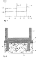
- FIG. 1 shows a typical course when loading a buffer layer according to the invention.
- Curves a and b each show different set materials from different buffer layers.
- the tension of the buffer layer with a course according to curve a increases steeply up to a value of just under 0.10 N / mm 2 . Up to this load, the compression of the buffer layer is only a few mm. This means that the buffer layer remains almost undeformed up to a load of 0.10 N / mm 2 . As soon as the load is in a range of approximately 0.10 N / mm 2 , it suddenly collapses and deforms by approximately 45 mm. The tension only increases again after this deformation path has been reached. Such a stress-deformation curve is typical for use in a tunnel structure according to FIG. 3, which is described in more detail below.
- the thickness of the buffer layer 1 is reduced by about 60% for a cheap material of the buffer layer 1, that is to say that the starting material was about 75 mm thick in this case.
- the material of the buffer layer is adjusted differently, it can be predetermined that the material collapses at a tension of approximately 0.06 N / mm 2 .
- the deformation path is designed for a material with the characteristic curve b so that it is deformable about 90 mm.
- the force increases up to the predetermined compressive force of 0.06 N / mm 2 without being able to significantly deform the material of the buffer layer.
- this predetermined compressive force is reached, the material suddenly collapses again until it has undergone a deformation of approximately 90 mm. After it is deformed by 90 mm, ie compressed, the material is maximally compressed. As a result, the voltage increases again with a further load.
- the tension on the first material layer can increase again, the two material layers moving towards each other have the possibility of covering a distance of up to 90 mm without the tension increasing further. The tension only increases again after this deformation path has been covered.
- the curve b of FIG. 1 is the typical course of a buffer layer 1, as used, for example, in a trough structure according to FIG. 2 can.
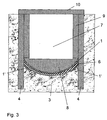
- a trough 2 is to be arranged on a base 3.
- the trough 2, which represents a first material layer, is anchored with piles 4 in the subsoil 3, which represents a second material layer.
- the substrate 3 consists of a swellable material, there is a fear that an impermissible compressive force will act on the trough 2.
- the buffer layer 1 is arranged between the trough 2 and the substrate 3.
- the buffer layer 1 serves both during the construction phase of the trough 2 to protect against swelling of the substrate 3, by compressing the buffer layer 1 between the substrate 3 and the cleanliness layer 5. Even after the trough 2 has been built, an inadmissible compressive stress on the part of the substrate 3 is absorbed by the buffer layer 1. The trough 2 is thus securely fastened in the base 3, without fear that the trough 2 will be damaged by the compressive stresses which may arise from the swelling of the base.
- FIG. 3 shows a further exemplary embodiment of an use of the buffer layer 1 according to the invention.
- piles 4 are first introduced into the subsoil 3.
- the subsurface 3 between the piles 4 is excavated to a predetermined depth by applying an overpressure.
- the base 3 is sealed by means of a shotcrete layer 6.
- the buffer layer 1 is applied to the shotcrete layer 6.
- Both the shotcrete layer 6 and the buffer layer 1 are arch-shaped in order to be able to absorb pressure forces which act on the shotcrete layer 6 from the substrate 3 more favorably.
- the vault is concave in order to obtain a good anchoring of the shotcrete 6 on the piles 4 and a corresponding force absorption of the shotcrete layer 6.
- the base plate 8 of the tunnel 7 is then concreted on the buffer layer 1.
- the buffer layer 1 must be so stable that it can absorb the load on the base plate 8 without collapsing. It may be necessary to use a load distribution plate, not shown, to make the buffer layer 1 more stable.
- the base plate 8 is made of in-situ concrete, so that the load-bearing capacity of the buffer layer 1 must be set up for the weight of the fresh concrete. Even after the in-situ concrete has hardened, construction vehicles which run on the base plate 8 must be carried by the buffer layer 1 without bringing them together.
- the remaining tunnel structure 7 is made by hanging it on the piles 4, the base plate 8 being connected to side walls 9 and a ceiling 10.
- a further buffer layer 1 ' is provided to secure the attachment of the shotcrete layer 6 to the piles 4.
- the buffer layer 1 ' absorbs movements of the substrate 3 in the area of the abutment of the shotcrete layer 6 on the piles 4 and thus relieves these bearing points.
- This buffer layer 1 ' is optional, that is, in most cases it is not necessary because the abutment of the shotcrete layer 6 on the piles is sufficiently strong.
- the shotcrete layer 6 When the substrate 3 moves, in particular when the substrate 3 swells, the shotcrete layer 6 is destroyed. After the shotcrete layer 6 is destroyed, the buffer layer 1 is also destroyed and, due to the inventive design of the buffer layer 1, suddenly free movement space. The void volume created by the collapse of the buffer layer 1 is filled by the swelling material of the substrate 3. No undue force is thus exerted on the base plate 8 and the entire tunnel structure 7. If the material of the buffer layer 1 has a characteristic as shown by curve a in FIG. 1, a movement path of approximately 45 mm is created for the swelling of the substrate 3. This is usually sufficient for such structures and a clay base.
- the buffer layer 1 is designed such that it can lose at least 60% of its original volume. If a deformation path of 60 mm is required, the original material of the buffer layer 1 must be made with a thickness of approximately 100 mm.
- the buffer layer can also be used between layers of material that run vertically to one another and move toward one another.
- the second layer of material does not have to be the underground in the form of a natural material such as clay or stone, but can also be an artificially created underground, such as another building.
- the compressive force at which the buffer layer 1 collapses can be adjusted, in particular by the choice of additives and residence time in the autoclave, so that values between 0.05 and 0.5 N / mm 2 are preferably achieved. Since the buffer layer 1 can no longer be walked on by people in a production for compressive forces less than 0.05 N / mm 2 without already suffering from deformation, the application of a load distribution plate, for example a water-resistant glued chipboard, is advantageous.
- the buffer layer 1 must be able to absorb the loads from the reinforcement, which are removed, for example, by spacers made of fiber concrete. A load distribution plate on the buffer layer may also be required for this.
Landscapes
- Engineering & Computer Science (AREA)
- Mining & Mineral Resources (AREA)
- Life Sciences & Earth Sciences (AREA)
- General Life Sciences & Earth Sciences (AREA)
- Paleontology (AREA)
- Civil Engineering (AREA)
- General Engineering & Computer Science (AREA)
- Structural Engineering (AREA)
- Environmental & Geological Engineering (AREA)
- Hydrology & Water Resources (AREA)
- Lining And Supports For Tunnels (AREA)
- Building Environments (AREA)
Applications Claiming Priority (2)
| Application Number | Priority Date | Filing Date | Title |
|---|---|---|---|
| DE2002149546 DE10249546A1 (de) | 2002-10-23 | 2002-10-23 | Bauwerk mit einer Pufferschicht und Verfahren zum Herstellen eines Bauwerks |
| DE10249546 | 2002-10-23 |
Publications (2)
| Publication Number | Publication Date |
|---|---|
| EP1413681A2 true EP1413681A2 (fr) | 2004-04-28 |
| EP1413681A3 EP1413681A3 (fr) | 2005-12-14 |
Family
ID=32049581
Family Applications (1)
| Application Number | Title | Priority Date | Filing Date |
|---|---|---|---|
| EP03024200A Withdrawn EP1413681A3 (fr) | 2002-10-23 | 2003-10-21 | Bâtiment avec une tamponage et procedée de installation |
Country Status (2)
| Country | Link |
|---|---|
| EP (1) | EP1413681A3 (fr) |
| DE (1) | DE10249546A1 (fr) |
Cited By (3)
| Publication number | Priority date | Publication date | Assignee | Title |
|---|---|---|---|---|
| EP2778291A1 (fr) * | 2013-03-13 | 2014-09-17 | HOCHTIEF Solutions AG | Procédé de fabrication d'une plaque de fondation éliminant les effets des séismes pour au moins un bâtiment |
| EP2857588A1 (fr) * | 2013-10-02 | 2015-04-08 | HOCHTIEF Solutions AG | Procédé et dispositif de réalisation d'une construction, notamment d'une construction offshore |
| CN114737608A (zh) * | 2022-05-08 | 2022-07-12 | 北京建筑大学 | 基于自复位截断柱的叠合式地下结构抗震体系及施工方法 |
Family Cites Families (5)
| Publication number | Priority date | Publication date | Assignee | Title |
|---|---|---|---|---|
| CH441681A (de) * | 1965-02-18 | 1967-08-15 | Anders Granstrom Sune | Fundamentvorrichtung für Bauwerke, z.B. Gebäude oder Gebäudeteile, zum Schützen derselben gegen Zerstörung infolge heftiger Bewegungen ihrer Unterlage |
| US4508472A (en) * | 1982-11-03 | 1985-04-02 | Iowa State University Research Foundation, Inc. | Method for controlling moisture-expansive clay supporting building foundations |
| SE459189B (sv) * | 1987-09-09 | 1989-06-12 | Pieux Armes Int | Foerfarande och anordning foer att paaverka samverkan mellan ett jordlager och en i anslutning till jordlagret befintlig konstruktion |
| CA2041324C (fr) * | 1991-04-26 | 1995-05-30 | Bruce M. Carruthers | Entretoise deformable |
| DE19701858A1 (de) * | 1997-01-21 | 1998-07-23 | Gerhard Fabritz | Neues Baustoff- und Dämmsystem auf Basis von Blähglasgranulat |
-
2002
- 2002-10-23 DE DE2002149546 patent/DE10249546A1/de not_active Withdrawn
-
2003
- 2003-10-21 EP EP03024200A patent/EP1413681A3/fr not_active Withdrawn
Cited By (3)
| Publication number | Priority date | Publication date | Assignee | Title |
|---|---|---|---|---|
| EP2778291A1 (fr) * | 2013-03-13 | 2014-09-17 | HOCHTIEF Solutions AG | Procédé de fabrication d'une plaque de fondation éliminant les effets des séismes pour au moins un bâtiment |
| EP2857588A1 (fr) * | 2013-10-02 | 2015-04-08 | HOCHTIEF Solutions AG | Procédé et dispositif de réalisation d'une construction, notamment d'une construction offshore |
| CN114737608A (zh) * | 2022-05-08 | 2022-07-12 | 北京建筑大学 | 基于自复位截断柱的叠合式地下结构抗震体系及施工方法 |
Also Published As
| Publication number | Publication date |
|---|---|
| EP1413681A3 (fr) | 2005-12-14 |
| DE10249546A1 (de) | 2004-05-06 |
Similar Documents
| Publication | Publication Date | Title |
|---|---|---|
| DE69700280T2 (de) | Verfahren zum Erhöhen der Belastbarkeit eines Fundamentsbodens für Bauwerke | |
| EP3112542B1 (fr) | Dispositif et procede de couplage thermique de parties betonnees de batiment | |
| DE69907752T2 (de) | Verfahren und vorrichtung zum abdichten von fugen oder rissen in hydraulischen werken, beton und mauerwerk | |
| DE3128419C2 (fr) | ||
| EP3085843B1 (fr) | Dispositif et procédé de couplage thermique de parties betonnées de bâtiment | |
| DE2534341B2 (de) | Verpreßanker | |
| EP1564369B1 (fr) | Procédé et appareil pour stabiliser une cavité souterraine éclaté | |
| AT520386A1 (de) | Verfahren zur Herstellung einer integralen Brücke und integrale Brücke | |
| EP3607147B1 (fr) | Fondation offshore | |
| DE2823950C2 (de) | Schachtausbau, insbesondere für den Ausbau tiefer Schächte in nicht standfestem, wasserführendem Gebirge | |
| DE102017121037A1 (de) | Verfahren zur Tragfähigkeitsverbesserung von im Baugrund gesetzten Profilen sowie Profil dafür | |
| EP1413681A2 (fr) | Bâtiment avec une tamponage et procedée de installation | |
| DE2700594A1 (de) | Verbau fuer eine baugrubenwand und verfahren zur herstellung | |
| DE102008009057A1 (de) | Holzmastegründung | |
| EP0109397B1 (fr) | Element de fondation creux et procede pour sa fabrication | |
| EP1108855B1 (fr) | Voûte étanche et autoportante pour l'étanchement des tunnels souterrains | |
| EP3106581B1 (fr) | Systeme d'isolation thermique destine a la liaison verticale a repartition de charge de parties de batiments a fabriquer en beton | |
| EP2287414A1 (fr) | Dispositif destiné à la réception d'énergie de déformation | |
| DE102016106036A1 (de) | Anschlussbauteil zur Wärmeentkopplung zwischen einem vertikalen und einem horizontalen Gebäudeteil | |
| EP0457969B1 (fr) | Méthode et dispositif pour soulever des ouvrages | |
| DE2831662A1 (de) | Ringausbau fuer schaechte, vorzugsweise gefrierschaechte des berg- und tunnelbaus | |
| EP2706148B1 (fr) | Procédé d'amélioration de la portance de profilés ouverts disposés dans le sol de fondation et système réalisé grâce à ce procédé | |
| DE3033715A1 (de) | Verfahren zur untergrundverbesserung und dazu dienender gruendungspfahl, -anker o.dgl. | |
| DE102021116487B3 (de) | Geotextilummantelte Flüssigbodensäulen | |
| DE4312267C2 (de) | Segment-Schacht für Deponien und andere hohe Aufschüttungen |
Legal Events
| Date | Code | Title | Description |
|---|---|---|---|
| PUAI | Public reference made under article 153(3) epc to a published international application that has entered the european phase |
Free format text: ORIGINAL CODE: 0009012 |
|
| AK | Designated contracting states |
Kind code of ref document: A2 Designated state(s): AT BE BG CH CY CZ DE DK EE ES FI FR GB GR HU IE IT LI LU MC NL PT RO SE SI SK TR |
|
| AX | Request for extension of the european patent |
Extension state: AL LT LV MK |
|
| PUAL | Search report despatched |
Free format text: ORIGINAL CODE: 0009013 |
|
| AK | Designated contracting states |
Kind code of ref document: A3 Designated state(s): AT BE BG CH CY CZ DE DK EE ES FI FR GB GR HU IE IT LI LU MC NL PT RO SE SI SK TR |
|
| AX | Request for extension of the european patent |
Extension state: AL LT LV MK |
|
| 17P | Request for examination filed |
Effective date: 20060512 |
|
| 17Q | First examination report despatched |
Effective date: 20060703 |
|
| AKX | Designation fees paid |
Designated state(s): AT BE BG CH CY CZ DE DK EE ES FI FR GB GR HU IE IT LI LU MC NL PT RO SE SI SK TR |
|
| GRAP | Despatch of communication of intention to grant a patent |
Free format text: ORIGINAL CODE: EPIDOSNIGR1 |
|
| STAA | Information on the status of an ep patent application or granted ep patent |
Free format text: STATUS: THE APPLICATION IS DEEMED TO BE WITHDRAWN |
|
| 18D | Application deemed to be withdrawn |
Effective date: 20100504 |