EP3085843B1 - Dispositif et procédé de couplage thermique de parties betonnées de bâtiment - Google Patents
Dispositif et procédé de couplage thermique de parties betonnées de bâtiment Download PDFInfo
- Publication number
- EP3085843B1 EP3085843B1 EP16164252.5A EP16164252A EP3085843B1 EP 3085843 B1 EP3085843 B1 EP 3085843B1 EP 16164252 A EP16164252 A EP 16164252A EP 3085843 B1 EP3085843 B1 EP 3085843B1
- Authority
- EP
- European Patent Office
- Prior art keywords
- thermal insulation
- insulation element
- concrete
- opening
- building
- Prior art date
- Legal status (The legal status is an assumption and is not a legal conclusion. Google has not performed a legal analysis and makes no representation as to the accuracy of the status listed.)
- Active
Links
Images




Classifications
-
- E—FIXED CONSTRUCTIONS
- E04—BUILDING
- E04B—GENERAL BUILDING CONSTRUCTIONS; WALLS, e.g. PARTITIONS; ROOFS; FLOORS; CEILINGS; INSULATION OR OTHER PROTECTION OF BUILDINGS
- E04B1/00—Constructions in general; Structures which are not restricted either to walls, e.g. partitions, or floors or ceilings or roofs
- E04B1/38—Connections for building structures in general
- E04B1/41—Connecting devices specially adapted for embedding in concrete or masonry
-
- E—FIXED CONSTRUCTIONS
- E04—BUILDING
- E04B—GENERAL BUILDING CONSTRUCTIONS; WALLS, e.g. PARTITIONS; ROOFS; FLOORS; CEILINGS; INSULATION OR OTHER PROTECTION OF BUILDINGS
- E04B1/00—Constructions in general; Structures which are not restricted either to walls, e.g. partitions, or floors or ceilings or roofs
- E04B1/16—Structures made from masses, e.g. of concrete, cast or similarly formed in situ with or without making use of additional elements, such as permanent forms, substructures to be coated with load-bearing material
- E04B1/165—Structures made from masses, e.g. of concrete, cast or similarly formed in situ with or without making use of additional elements, such as permanent forms, substructures to be coated with load-bearing material with elongated load-supporting parts, cast in situ
-
- E—FIXED CONSTRUCTIONS
- E04—BUILDING
- E04B—GENERAL BUILDING CONSTRUCTIONS; WALLS, e.g. PARTITIONS; ROOFS; FLOORS; CEILINGS; INSULATION OR OTHER PROTECTION OF BUILDINGS
- E04B1/00—Constructions in general; Structures which are not restricted either to walls, e.g. partitions, or floors or ceilings or roofs
- E04B1/62—Insulation or other protection; Elements or use of specified material therefor
- E04B1/74—Heat, sound or noise insulation, absorption, or reflection; Other building methods affording favourable thermal or acoustical conditions, e.g. accumulating of heat within walls
- E04B1/76—Heat, sound or noise insulation, absorption, or reflection; Other building methods affording favourable thermal or acoustical conditions, e.g. accumulating of heat within walls specifically with respect to heat only
-
- E—FIXED CONSTRUCTIONS
- E04—BUILDING
- E04B—GENERAL BUILDING CONSTRUCTIONS; WALLS, e.g. PARTITIONS; ROOFS; FLOORS; CEILINGS; INSULATION OR OTHER PROTECTION OF BUILDINGS
- E04B1/00—Constructions in general; Structures which are not restricted either to walls, e.g. partitions, or floors or ceilings or roofs
- E04B1/62—Insulation or other protection; Elements or use of specified material therefor
- E04B1/74—Heat, sound or noise insulation, absorption, or reflection; Other building methods affording favourable thermal or acoustical conditions, e.g. accumulating of heat within walls
- E04B1/76—Heat, sound or noise insulation, absorption, or reflection; Other building methods affording favourable thermal or acoustical conditions, e.g. accumulating of heat within walls specifically with respect to heat only
- E04B1/78—Heat insulating elements
-
- E—FIXED CONSTRUCTIONS
- E04—BUILDING
- E04C—STRUCTURAL ELEMENTS; BUILDING MATERIALS
- E04C5/00—Reinforcing elements, e.g. for concrete; Auxiliary elements therefor
- E04C5/01—Reinforcing elements of metal, e.g. with non-structural coatings
- E04C5/06—Reinforcing elements of metal, e.g. with non-structural coatings of high bending resistance, i.e. of essentially three-dimensional [3D] extent, e.g. lattice girders
-
- E—FIXED CONSTRUCTIONS
- E04—BUILDING
- E04B—GENERAL BUILDING CONSTRUCTIONS; WALLS, e.g. PARTITIONS; ROOFS; FLOORS; CEILINGS; INSULATION OR OTHER PROTECTION OF BUILDINGS
- E04B1/00—Constructions in general; Structures which are not restricted either to walls, e.g. partitions, or floors or ceilings or roofs
- E04B1/62—Insulation or other protection; Elements or use of specified material therefor
- E04B1/74—Heat, sound or noise insulation, absorption, or reflection; Other building methods affording favourable thermal or acoustical conditions, e.g. accumulating of heat within walls
- E04B1/76—Heat, sound or noise insulation, absorption, or reflection; Other building methods affording favourable thermal or acoustical conditions, e.g. accumulating of heat within walls specifically with respect to heat only
- E04B2001/7679—Means preventing cold bridging at the junction of an exterior wall with an interior wall or a floor
-
- E—FIXED CONSTRUCTIONS
- E04—BUILDING
- E04C—STRUCTURAL ELEMENTS; BUILDING MATERIALS
- E04C3/00—Structural elongated elements designed for load-supporting
- E04C3/30—Columns; Pillars; Struts
- E04C3/34—Columns; Pillars; Struts of concrete other stone-like material, with or without permanent form elements, with or without internal or external reinforcement, e.g. metal coverings
-
- E—FIXED CONSTRUCTIONS
- E04—BUILDING
- E04C—STRUCTURAL ELEMENTS; BUILDING MATERIALS
- E04C5/00—Reinforcing elements, e.g. for concrete; Auxiliary elements therefor
- E04C5/01—Reinforcing elements of metal, e.g. with non-structural coatings
- E04C5/06—Reinforcing elements of metal, e.g. with non-structural coatings of high bending resistance, i.e. of essentially three-dimensional [3D] extent, e.g. lattice girders
- E04C5/0604—Prismatic or cylindrical reinforcement cages composed of longitudinal bars and open or closed stirrup rods
Definitions
- the present invention relates to a thermal insulation element for heat decoupling between load-bearing parts of the building to be made of concrete, preferably between a vertical part of the building, in particular a contactor, and a horizontal part of the building above or below it, in particular a floor or a floor slab.
- load-bearing parts of buildings are often created from reinforced concrete structures.
- such parts of the building are usually provided with external thermal insulation.
- the floor ceiling between the basement, such as a basement or underground garage, and the ground floor is often equipped with thermal insulation on the basement side.
- This is usually achieved by monolithically connecting the floor slab to the load-bearing columns and external walls with continuous reinforcement.
- this creates thermal bridges that are difficult to remove by means of external thermal insulation.
- the upper section of the load-bearing concrete columns facing the floor ceiling is also clad with thermal insulation. This is not only complex and visually unappealing, but also leads to unsatisfactory building physics results and also reduces the parking space available in the underground car park.
- the thermal insulation element has a pressure-resistant support structure with insulating elements arranged in the spaces.
- the supporting structure can consist of a lightweight concrete, for example.
- Such a thermal insulation element is used for the thermal insulation of brick outer walls, for example by using it like a conventional brick as the first stone layer of the load-bearing outer wall above the basement ceiling.
- a pressure-transmitting and insulating connecting element which is used for the vertical, load-bearing connection of building parts to be made of concrete. It consists of an insulation body with one or more pressure elements embedded in it. Shear force reinforcement elements run through the pressure elements and, for connection to the parts of the building to be made of concrete, extend essentially vertically beyond the top and the bottom of the insulation body.
- the insulation body can be made of foam glass or expanded polystyrene hard foam, for example, and the pressure elements can be made of concrete, fiber concrete or fiber plastic.
- EP 0 745 733 A1 discloses a cantilever plate or joint element for the horizontal connection of building parts.
- the publication DE 10 2005 001 270 A1 discloses a component for reinforced concrete construction, comprising a square base plate and a plurality of L-shaped angle iron, the angle iron are fixed by welding to a large side of the base plate in each case at one of the four corners or on the side faces of the base plate around one of the four corners, wherein the base plate has at least one through hole provided for receiving cables and wires and at least one recess provided for filling in the concrete.
- connection element When installing such a prefabricated connecting element, the reinforcement elements must also be cast when concreting the adjacent parts of the building.
- the connection element must be installed in a closed formwork for the underlying part of the building and it must be concreted from below against the existing, inaccessible and invisible underside of the connection element.
- supports and external walls in particular, which are load-bearing structural parts
- a poor design when building the building parts, particularly at the connection point to the connecting element can later lead to serious structural problems on the building.
- the object of the invention is therefore to
- the invention is therefore based on the object of specifying a thermal insulation element which enables reliable installation at a vertically load-bearing connection point between two parts of the building to be made of concrete.
- the invention relates to a method for installing a corresponding thermal insulation element.
- a thermal insulation element which consists at least partially of a pressure-transmitting material and has an upper and a lower contact surface for vertical connection to the parts of the building to be made of concrete
- the object is achieved in that the thermal insulation element is at least one from the upper to the lower Has support surface extending through opening, which is designed for performing a compression device.
- the through opening thus serves as an immersion point for an internal vibrator.
- the through opening in the thermal insulation element is preferably arranged approximately in the center.
- one or more rod-shaped reinforcement elements are provided which penetrate the thermal insulation element and which extend substantially vertically beyond the upper and lower contact surfaces.
- the present invention is based on the knowledge that during installation and subsequent concreting against the underside of the thermal insulation element, inadequate and undefined compression of the in-situ concrete below the thermal insulation element can occur, which also depends strongly on the composition of the in-situ concrete used.
- two processes on the underside of the thermal insulation element when the in-situ concrete sets can result in the load-bearing connection of the thermal insulation element to the underlying building part being inadequate.
- rising air bubbles, so-called compression pores can lead to the formation of voids on the underside of the thermal insulation element and thus ensure a structurally inadequate connection.
- the reinforcement elements serve to connect the thermal insulation element to the adjacent parts of the building and, if necessary, will be connected to their reinforcement.
- a monolithic connection of the building parts is thus achieved, even if, due to static requirements, the connection is only regarded as a concrete joint and the reinforcement elements thus perform a more constructive function without any major significance for the building statics.
- a passage opening is provided in the thermal insulation element according to the invention, through which a compacting device such as the vibrating bottle of a concrete vibrator can be passed, in order to compact or re-compact the in-situ concrete underneath after installing the thermal insulation element.
- the thermal insulation element is at least partially made of a pressure-transmitting and heat-insulating material.
- This material can preferably be a lightweight concrete.
- High-pressure resistant molded elements with low specific thermal conductivity can be produced from lightweight concrete under factory conditions.
- such a lightweight concrete molded part can comprise, in addition to the through opening according to the invention, further hollow chambers or enclosed insulating elements.
- a concrete with a dry bulk density of maximum 2000 kg / m 3 is defined under lightweight concrete according to the applicable regulations.
- the low density compared to normal concrete is achieved through appropriate manufacturing processes and different lightweight concrete grains such as grains with grain porosity such as expanded clay.
- lightweight concrete has a thermal conductivity between 0.2 and 1.6 W / (m ⁇ K).
- a thermal insulation element made of lightweight concrete also acts as a stress-damping element and is able to compensate for smaller settlements and elastic deformations of the part of the building above and a more even distribution and force transmission from eccentric bearing forces on or into the part of the building below, in particular a support. ensure.
- the much lower modulus of elasticity of the lightweight concrete used has a particularly favorable effect on load centers and bearing twists, which result in increased edge pressures. Due to its elastic properties, the thermal insulation element acts as a "centering element", so to speak. In contrast to this, the compression with a central load is of minor importance.
- the typical modulus of elasticity of normal concrete, as used for a column, is approximately E cm ⁇ 30,000 to 40,000 N / mm 2 .
- the modulus of elasticity of the lightweight concrete preferred in the context of the invention is between approximately 9,000 and 22,000 N / mm 2 , preferably 12,000 and 16,000 N / mm 2 , most preferably approximately 14,000 N / mm 2 .
- the thermal insulation element can also consist of a heat-insulating but not pressure-transmitting insulating body, for example of extruded polystyrene with one or more pressure bodies embedded therein.
- Such pressure hulls can be made from high-strength concrete, in which case the thermal conductivity of the thermal insulation element is reduced by a correspondingly small base area of the pressure elements.
- the latter variant Compared to a solid or hollow block thermal insulation element made of lightweight concrete, the latter variant has the disadvantage due to the significantly smaller contact area that even smaller weak points in the connection to the underlying part of the building due to the formation of voids or sedimentation have a significantly stronger impact on the structural stability of the construction. In the worst case, local overloading and thus failure of individual pressure elements of the thermal insulation element can occur. This risk is significantly lower due to the much larger contact surface with a thermal insulation element made of a material that transmits pressure, such as lightweight concrete.
- a further advantage of the present invention results if the lower contact surface of the thermal insulation element has a surface with a three-dimensional profile. Suitable profiling of the surface further reduces defects in the connection between the thermal insulation element and the freshly concreted part of the building underneath.
- the surface may have elevations and depressions as well as inclined surfaces, furrows, or the like, so that in the event of sedimentation, the surface water that settles out can run or settle in non-critical areas, while in areas of the thermal insulation element that are critical for the static connection intimate connection to the fresh concrete of the part of the building underneath is created.
- an embodiment is considered to be particularly preferred in which the lower bearing surface has a funnel-shaped or curved surface that is inclined or curved in the direction of the passage opening. This ensures that in the event of sedimentation, the surface water that is deposited is displaced in the direction of the passage opening or only forms in this area, which does not contribute to the statics of the construction anyway.
- the reinforcement elements can preferably be designed as reinforcement bars, which are used primarily for the transmission of tensile forces. Reinforcement elements that have to pass through thermal insulation are often made of stainless steel or stainless steel for structural reasons. In the context of the present invention, for reasons of better thermal insulation, the reinforcement elements can preferably be made of a fiber composite material such as glass fiber reinforced plastic.
- a reinforcement bracket is arranged in the thermal insulation element in the interior of the material transmitting the compressive force.
- a reinforcement bracket in the form of a self-contained reinforcement ring with, for example, a circular or rounded polygonal base surface, which is arranged in a plane that is essentially parallel to the support surfaces, can further increase the resistance to pressure force of the thermal insulation element by minimizing the transverse expansion of the thermal insulation element under pressure.
- a further advantageous aspect of the present invention results if at least one seal is provided on the thermal insulation element around its vertical boundary surfaces, which seal ensures tight installation of the thermal insulation element in a formwork for the underlying part of the building.
- a seal prevents fresh concrete from penetrating and rising between the formwork and the thermal insulation element when the thermal insulation element is inserted or the underlying part of the building is concreted.
- such a seal prevents air from penetrating between the formwork and the thermal insulation element if, after compacting, the vibrating tool is pulled out of the passage opening of the thermal insulation element and the thermal insulation element drops by the volume previously displaced by the vibrating tool within the formwork of the building part below.
- potting openings can be provided in the thermal insulation element, via which additional casting compound, such as potting mortar, can be filled in, if necessary, after the concrete has hardened, in order to fill any cavities that still exist between the part of the building underneath and the thermal insulation element.
- additional casting compound such as potting mortar
- the potting openings in question are preferably closed by means of removable blind plugs, so that they cannot be blocked by in-situ concrete when the thermal insulation element is installed.
- a sealing plug is provided, with which the through opening can be subsequently closed.
- the sealing plug consists of a heat-insulating but non-load-bearing material, such as, for example, extruded polystyrene.
- such a sealing plug can be conically shaped so that it can be inserted sealingly into the through opening, which preferably also tapers downwards. This ensures that after the thermal insulation element has been installed, no thermal bridge remains through the through opening, for example due to in-situ concrete entering the through opening when concreting the floor slab above it.
- one or more indicators can be provided in the thermal insulation element, which indicate sufficient contact of the lower contact surface with the fresh concrete of the part of the building to be created below.
- such indicators can be designed in the manner of a float, for example. If the indicators on the upper contact surface of the thermal insulation element become visible when there is sufficient contact, it is ensured that there is sufficient contact with the underlying concrete surface.
- the through opening has an opening dimension which is large enough to allow the passing of vibrating bottles customary on the construction site, in particular of at least 50 mm, preferably between 60 and 80 mm.
- the invention also relates to a method for installing such a thermal insulation element between two load-bearing parts of the building to be made of concrete, preferably between a vertical part of the building, in particular a support, and a horizontal part of the building above or below it, in particular a floor or a floor slab.
- formwork is created for the lower part of the building and the lower part of the building is concreted by pouring in-situ concrete into the formwork and compacting it.
- the thermal insulation element is inserted into the formwork for the lower part of the building.
- the reinforcement elements which possibly protrude downward beyond the thermal insulation element pressed into the fresh in-situ concrete of the lower part of the building.
- the concrete is subsequently compacted in a subsequent step by means of a compacting device which is passed through the through-opening in the thermal insulation element.
- the passage opening can then preferably be closed by means of a sealing plug.
- the upper part of the building for example a floor ceiling, can be created above the thermal insulation element in a conventional manner.
- the thermal insulation element can also be installed before the formwork is filled with in-situ concrete.
- the passage opening can initially be used as a filling opening for the in-situ concrete.
- the filled concrete is then compacted by inserting the vibrating tool into the fresh in-situ concrete through the through opening.
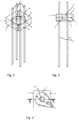
- the thermal insulation element 1 shown is used for the monolithic connection and for the load-bearing connection of a concrete column in the basement of a building to the basement ceiling above. It has a cuboid base element 1 with an upper side 2 and an underside 3, each of which serves as a support surface for the basement ceiling or the end of the support that supports it. In the middle of the cuboid thermal insulation element 1 there is a central through opening 4, which extends from the top 2 to the bottom 3 of the thermal insulation element 1.
- Four reinforcing bars 5 project through the thermal insulation element.
- the underside 3 of the thermal insulation element 1 has a three-dimensional profile in the form of a funnel-shaped recess 6 which extends in the direction of the through opening 4.
- a reinforcement bracket 7 embedded which is around the reinforcing bars 5 and gives the thermal insulation element additional stability.
- the thermal insulation element 1 consists of a lightweight concrete, which on the one hand has high pressure stability and on the other hand has good thermal insulation properties. Compared to concrete with a thermal conductivity of about 1.6 W / (m ⁇ K), the thermal conductivity when using a suitable lightweight concrete material is in the range of about 0.5 W / (m ⁇ K), which corresponds to an improvement of about 70%.
- the light concrete used essentially consists of expanded clay, fine sand, preferably light sand, flow agents and stabilizers, which prevent segregation by floating the grain and improve workability.
- the compressive strength of the thermal insulation element is high enough to allow the statically planned use of the underlying column made of in-situ concrete, for example in accordance with the compressive strength class C25 / 30.
- the compressive strength of the thermal insulation element preferably corresponds to at least 1.5 times the statically required value. This ensures that there are also safety reserves in the event of any missing surfaces on the connecting surface between the thermal insulation element and the support, so that the thermal insulation element remains statically stable even at points with higher loads.
- the reinforcing bars 5 can be concreted into the lightweight concrete material of the cuboid base body 1 during the manufacture of the thermal insulation element.
- sleeves during manufacture it is possible to use sleeves during manufacture as a type of lost circuit through which the reinforcing bars 5 are inserted after the lightweight concrete element 1 has hardened.
- the reinforcement bars 5 themselves are in the exemplary embodiment made of a fiber composite material such as the proven ComBAR® reinforcement bar from Schock, which consists of glass fibers aligned in the direction of the force and a synthetic resin matrix.
- a glass fiber rebar has an extreme low thermal conductivity, which is up to 100 times lower than that of reinforcing steel, and is therefore ideal for use in the thermal insulation element.
- conventional reinforcement bars made of stainless steel or structural steel can also be used.
- the described use of sleeves as lost formwork for the subsequent insertion of the reinforcement bars is advantageous.
- Reinforcing bars made of fiber composite materials can transmit very high tensile forces, in contrast, however, significantly lower compressive forces can destroy the reinforcing bars.
- the use of sleeves avoids a form-fitting embedding of the reinforcing bars in the surrounding concrete, which is normally intended for concrete reinforcement and is almost essential. If there is a compressive load, for example due to subsidence in the building, the reinforcement bars in their sleeves can deform elastically until the compressive forces are completely removed by the compressive-stable insulating body 1, so that a harmful compressive load on the reinforcement bars is avoided.
- the reinforcement in the thermal insulation element is only designed as a tensile reinforcement, since the connection between the support and the floor slab above it can be considered statically anyway as an articulated connection.
- a stable and permanent connection or monolithic connection between the column and the floor slab according to the static requirements is achieved with continuous reinforcement.
- the dimensions of the reinforcing bars 5 are, without the invention being restricted to this, in the exemplary embodiment 16 mm in diameter and 930 mm in length.
- the arrangement of the reinforcing bars 5 based on the base area of the base body 1 is chosen slightly outside the main diagonals. The reason for this is that the reinforcement of the support is already in the corners of a support in which the reinforcing bars 5 of the thermal insulation element 1 are installed.
- the reinforcement bracket 7 consists of a ring bent stainless steel, which is welded at the connection point.
- the reinforcement bracket 7 has a diameter of approximately 200 mm with a material thickness of 8 mm or 10 mm.
- the basic body of the thermal insulation element 1 has an edge length of 250 x 250 mm in the exemplary embodiment.
- the height is 100 mm and thus corresponds to the usual thickness of a subsequently installed thermal insulation layer.
- the through opening runs, especially in Fig. 3 can be seen, slightly conical in that the through opening 4 tapers from an upper dimension of 70 mm to a lower dimension of 65 mm.
- the through opening can be closed by means of a corresponding likewise slightly conical plug (not shown).
- Fig. 4 shows the thermal insulation element in a side view, wherein additional peripheral seals 8 are attached to the base body 1.
- the seals 8 can be designed, for example, as rubber lips or conventional sealing tapes. They are used to seal the base body of the thermal insulation element 1 so that it is edge-tight against a formwork for the support to be created underneath, in order to prevent concrete from rising or air from entering.
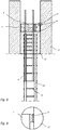
- Fig. 5 shows the installation situation of the thermal insulation element in relation to a support 23.
- the cross section shown here runs below the base body of the thermal insulation element 1.
- the support 23 made of in-situ concrete has one Reinforcement with four vertical reinforcement bars 25 arranged in the corners of the support 23 and a large number of approximately square reinforcement bars 26 running horizontally around the reinforcement bars 25.
- the reinforcement bars 5 of the thermal insulation element are each slightly offset next to one of the reinforcement bars 25 of the support 23 Fig. 5 drawn section line BB corresponds to the cut of the in Fig. 7 shown longitudinal section through the column reinforcement.
- FIG 6 a longitudinal section through the support 23 and the connected parts of the building is shown first.
- the support 23 is placed on a base plate 21 and carries a floor ceiling 22 arranged above it. This can be, for example, the basement or basement ceiling of a building.
- Base plate 21, support 23 and floor ceiling 22 are statically connected to one another.
- the compressive force-transmitting thermal insulation element 1 is arranged, the reinforcing bars 5 of which are monolithically cast both in the support 23 and in the floor ceiling 22 above.
- a thermal insulation layer 24 is applied to the underside of the floor ceiling 22, the thickness of which essentially corresponds to the height of the base body of the thermal insulation element 1.
- the thermal barrier coating 24 consists of a highly insulating material applied, for example of mineral insulation panels or wood wool multi-layer panels.
- Fig. 7 the reinforcement of the support 23 together with the thermal insulation element 1 is shown in a longitudinal section.
- the cut corresponds to the cut line BB Fig. 5 .
- the reinforcement of the support 23 consists of four vertical reinforcement bars 25 arranged in the corners of the support, which can be made, for example, of structural steel with a bar diameter of 28 mm and a length of 2000 mm, as well as a plurality of reinforcement brackets running horizontally around the reinforcement bars 25 with in roughly square plan.
- the thermal insulation element 1 is located above the column reinforcement, the reinforcing bars 5 of which protrude downward into the column reinforcement.
- the reinforcement content of the column 23 is about 3-4%. With a typical heat conductivity of the structural steel of approx. 50 W / (m ⁇ K), it contributes to concrete 1.6 W / (m ⁇ K) in about half of the total thermal conductivity of the column. By using the combination of lightweight concrete and glass fiber reinforcement in the area of the thermal insulation element 1, the heat transfer between the support 23 and the floor ceiling 22 can thus be reduced by approximately 90% compared to a direct, monolithic connection.
- a formwork 27 installed around the column reinforcement 25, 26 and filled with in-situ concrete. This is compacted in a conventional manner with an internal vibrator. Then the thermal insulation element 1 is inserted into the formwork 27 from above and the reinforcing bars 5 are pressed into the still liquid in-situ concrete. The base body 1 is pressed against the fresh in-situ concrete until the liquid concrete rises slightly upwards in the passage opening 4, so that it is ensured that there is no longer an air gap between the concrete of the support 23 and the thermal insulation element 1. The vibrating bottle of a concrete vibrator is then passed through the passage opening 4 into the fresh in-situ concrete located below, in order to compact it again.
- the thermal insulation element When inserting the vibrating bottle, the thermal insulation element can be slightly raised by the volume of the concrete displaced by the vibrating bottle. When pulling out the vibrating bottle, care is therefore taken to ensure that the thermal insulation element 1 drops again by this volume by pressing the thermal insulation element 1 down accordingly when the vibrator is pulled out.
- the circumferential seal 8 prevents air from penetrating between the formwork 27 and the thermal insulation element 1 or the thermal insulation element 1 from tilting in the formwork 27.
- detail designated as detail D is drawn out again enlarged by one of the seals 8.
- the post-compression of the still liquid fresh concrete through the through opening of the thermal insulation element 1 leads to an intimate connection of the thermal insulation element 1 with the in-situ concrete located underneath.
- hollow spots due to the formation of voids or sedimentation in the fresh concrete between the thermal insulation element 1 and the support are prevented.
- the conical profile on the underside of the base body 1 also contributes to this, due to the rising air bubbles or on the Collect surface of separated cement water mainly in the central area of the passage opening 4.
- the passage opening 4 is then closed by means of a conical stopper (not shown).
- the sealing plug can be made of an insulating material such as polystyrene or the like. exist and serves to prevent the penetration of in-situ concrete into the through opening 4 when the floor ceiling 22 is subsequently created. In this way, any thermal bridges due to a concrete filling in the through opening 4 are avoided. Subsequently, the storey ceiling 22 above is created above the thermal insulation element 1 in a conventional manner.
- the through opening 4 can also be used as a filling opening for filling the formwork for the support 23 with in-situ concrete.
- the thermal insulation element is inserted into the still empty formwork of the support 23 and, if necessary, the reinforcement bars 5 are connected to the support reinforcement.
- Fresh concrete is then poured into the formwork through the opening 4 of the thermal insulation element and then compacted by inserting a vibrating bottle of an internal vibrator through the opening 4.
- the fresh concrete is compacted against the underside of the thermal insulation element from above through the through opening 4.
- the support 23 can also be made from self-compacting concrete, or the support can be compacted by an external vibrator. In the latter two cases, the through opening 4 thus serves only as a filling opening.
- FIG Figure 10 In addition to installation in the upper area of a support, installation in the foot area of a support is also conceivable. Such an arrangement is shown in FIG Figure 10 shown.
- the support 23 is arranged here between the base plate 21 and the upper floor 22.
- a thermal insulation element 1 according to the invention is installed in the foot region of the support 23, the reinforcement bars 5 of which protrude from the base plate 21 into the upper region of the support 1 and are connected there to the reinforcement 25 of the support 1 are.
- a heat insulation layer 24 'made of insulation boards of a known type is attached to the top of the floor board 21.
- the production can be carried out in such a way that the thermal insulation element 1 is connected to the reinforcement 21 'before the base plate 21 is concreted.
- the base plate 21 is then cast from in-situ concrete, so that the concrete rises against the thermal insulation element 1 from below.
- the in-situ concrete can in turn be compacted through the central through opening 4 with a vibrating tool.
- the reinforcement 25 of the support is created and connected to the reinforcing bars 5 of the thermal insulation element.
- the formwork 27 for the support 23 is then built up around the thermal insulation element 1 and then the support 23 is poured and compacted from in-situ concrete in a conventional manner.
- Fig. 11 Another embodiment of a thermal insulation element is shown.
- the base body 10 of the thermal insulation element shown here is not made from lightweight concrete, but rather from a thermal insulation material which does not transmit compressive force, such as foam glass or rigid polystyrene foam.
- a total of four individual pressure bodies 11a to 11d, which are inserted into the insulation body 10, are used for the transmission of pressure force.
- the individual pressure elements 11a to 11d are made of a high-strength concrete in order to be able to remove the load through the building part 22 lying above. Reinforcing bars 15 are cast into the individual pressure elements 11a to 11d and project in the vertical direction beyond the top 12 and the bottom 13 of the thermal insulation element 10.
- a through opening 14 is provided approximately in the middle, as in the previous exemplary embodiment, which serves as a filling and / or compression opening.
- the thermal insulation element 10 is installed as in the previous exemplary embodiment.
- the thermal insulation property is achieved in this exemplary embodiment mainly by reducing the area of thermal bridges to the few individual pressure elements 11a to 11d.
- the present invention is not limited to the shape and number shown in the exemplary embodiment limited by single print elements. Rather, the portion of the pressure force-transmitting material provided within the insulation body 10 can be embodied in a variety of other geometries, such as, for example, in the form of a pressure-force-transmitting cylindrical ring.
- the reinforcing bars 15 also do not necessarily have to be guided through the pressure-force-transmitting regions 11a to 11d arranged in the insulation body 10, but can also be inserted separately therefrom through the non-pressure-force-transmitting regions of the thermal insulation element 10.
- thermal insulation element itself can be adapted to the component located below and / or above it.
- thermal insulation elements can be adapted to the typical cross sections of supports with a round, square or rectangular outline. Typical dimensions of round supports are diameters of 24 and 30 cm, or of supports with a rectangular layout of 25 x 25 cm and 30 x 30 cm. Thermal insulation elements with such a geometry can also be combined as desired to form larger supports or retaining walls.
- thermal insulation elements described here are particularly suitable for use with pendulum supports as well as wall supports with low clamping moments.
- use with load-bearing outer walls is also possible by installing the heat insulation elements at a suitable distance from one another and, if necessary, filling any remaining gaps between the individual heat insulation elements with non-load-bearing insulation material.
- the geometrical design of the profiled underside of the thermal insulation element can also be realized in a variety of other ways, for example in a step shape, a radial toothing, an annular bead and much more.
- openings can additionally or alternatively be provided for subsequent grouting of any remaining cavities between the thermal insulation element and the concrete surface located underneath.
- Such openings can be closed by means of blind plugs and, if necessary, opened to cover any remaining cavity by means of a potting compound such as one Subsequent filling of grout or a synthetic resin mass and thus establishing a secure static connection, even if in individual cases a faulty execution when creating the support or installing the thermal insulation element had resulted in a defective connection.
- indicators can be provided on the thermal insulation element, which can be pushed up in the manner of a float and thereby indicate that the thermal insulation element has contact with the in-situ concrete located underneath on its underside.
- thermal insulation element When installing the thermal insulation element in the already compacted, fresh concrete of the support underneath, during subsequent compacting and when pulling out the compacting tool from the through opening of the thermal insulation element, it may be advantageous if a defined pressure force is exerted on the thermal insulation element.
- rod-shaped reinforcing means for connecting the thermal insulation element to the parts of the building above and below can also be used in the context of the present invention, for example threaded rods, dowels or the like, since, as explained above, the connection between a support and a floor slab above it statically as a joint connection can be considered and the reinforcement at this point must therefore preferably have a constructive function.
Landscapes
- Engineering & Computer Science (AREA)
- Architecture (AREA)
- Physics & Mathematics (AREA)
- Civil Engineering (AREA)
- Structural Engineering (AREA)
- Electromagnetism (AREA)
- Acoustics & Sound (AREA)
- Building Environments (AREA)
Claims (14)
- Elément d'isolation thermique dévolu au découplage thermique et à la liaison, avec dissipation de charges verticales, de parties porteuses (23, 22) de bâtiments devant être confectionnées en béton, de préférence entre une partie verticale d'un bâtiment, notamment un pilier (23), et une partie horizontale dudit bâtiment occupant une position sus-jacente ou sous-jacente, notamment un plafond d'étage (22) ou une dalle de planchéiage (21), ledit élément (1) d'isolation thermique étant au moins partiellement constitué d'un matériau transmetteur de forces de pression, et étant pourvu de surfaces d'appui (2, 3) supérieure et inférieure, affectées au rattachement vertical auxdites parties (23, 22) du bâtiment,
caractérisé par le fait que
ledit élément (1) d'isolation thermique est muni d'au moins un orifice traversant (4) qui s'étend de la surface d'appui (2) supérieure à la surface d'appui (3) inférieure et est destiné au passage d'un appareil de compactage de béton frais, ainsi que d'un ou plusieurs élément(s) d'armature (5) en forme de tige, qui traverse(nt) ledit élément (1) d'isolation thermique de part en part et s'étend(ent), pour l'essentiel, verticalement au-delà desdites surfaces d'appui (2, 3) supérieure et inférieure. - Elément d'isolation thermique selon la revendication 1, au moins partiellement constitué d'un matériau transmetteur de forces de pression et thermiquement isolant.
- Elément d'isolation thermique selon la revendication 2, au moins partiellement constitué d'un béton léger.
- Elément d'isolation thermique selon l'une des revendications précédentes, dans lequel la surface d'appui (3) inférieure est dotée d'une surface à profilage tridimensionnel.
- Elément d'isolation thermique selon la revendication 4, dans lequel la surface d'appui (3) inférieure est dotée d'une surface à inclinaison ou bombement infundibuliforme en direction de l'orifice traversant (4).
- Elément d'isolation thermique selon la revendication 1, dans lequel les éléments d'armature (5) en forme de tige se présentent comme des baguettes d'armature constituées, de préférence, d'un matériau composite fibreux.
- Elément d'isolation thermique selon la revendication 1 ou 6, dans lequel les éléments d'armature (5), en forme de tige, sont insérés dans des manchons noyés dans le matériau transmetteur de forces de pression.
- Elément d'isolation thermique selon l'une des revendications précédentes, muni d'un étrier d'armature (7) logé à l'intérieur du matériau transmetteur de forces de pression.
- Elément d'isolation thermique selon l'une des revendications précédentes, doté d'au moins une garniture d'étanchement (8) s'étendant périphériquement autour de ses surfaces de délimitation verticale en vue de l'intégration dudit élément (1) d'isolation thermique, avec effet d'étanchement, dans un coffrage (27) dédié à la partie (23) du bâtiment qui occupe une position sous-jacente.
- Elément d'isolation thermique selon l'une des revendications précédentes, additionnellement pourvu d'un ou plusieurs orifice(s) de coulage, plus petit(s) que l'orifice traversant (4) et obturé(s), de préférence, au moyen de bouchons borgnes amovibles.
- Elément d'isolation thermique selon l'une des revendications précédentes, muni d'un bouchon obturateur préférentiellement tronconique, affecté à l'obturation de l'orifice traversant (4) à un stade ultérieur, lequel bouchon obturateur consiste, de préférence, en un matériau thermiquement isolant.
- Elément d'isolation thermique selon l'une des revendications précédentes, doté d'un ou plusieurs indicateur(s) conçu(s) pour signaler un contact suffisant de la surface d'appui (3) inférieure avec du béton non durci de la partie (23) du bâtiment devant être confectionnée en sous-jacence.
- Elément d'isolation thermique selon l'une des revendications précédentes, dans lequel l'orifice traversant (4) présente une cote d'au moins 50 mm, de préférence comprise entre 60 et 80 mm.
- Procédé d'intégration d'un élément (1) d'isolation thermique dévolu au découplage thermique entre des parties porteuses (23, 22, 21) de bâtiments devant être confectionnées en béton, de préférence entre une partie verticale d'un bâtiment, notamment un pilier (23), et une partie horizontale dudit bâtiment occupant une position sus-jacente ou sous-jacente, notamment un plafond d'étage (22) ou une dalle de planchéiage (21), sachant que l'élément (1) d'isolation thermique est au moins partiellement constitué d'un matériau transmetteur de forces de pression, et est pourvu de surfaces d'appui (2, 3) supérieure et inférieure, affectées au rattachement vertical auxdites parties (23, 22, 21) du bâtiment, et sachant que ledit élément (1) d'isolation thermique est muni d'au moins un orifice traversant (4) qui s'étend de la surface d'appui supérieure à la surface d'appui inférieure,
incluant les étapes suivantes :- déversement de béton dans un coffrage dédié à la partie inférieure (23) du bâtiment, et compactage dudit béton,- insertion de l'élément (1) d'isolation thermique dans ledit coffrage dédié à la partie inférieure (23) du bâtiment,- post-compactage du béton au moyen d'un appareil de compactage destiné à du béton frais, et guidé de part en part dans l'orifice traversant (4) et, de préférence,- obturation subséquente dudit orifice traversant (4) au moyen d'un bouchon obturateur.
Priority Applications (1)
| Application Number | Priority Date | Filing Date | Title |
|---|---|---|---|
| PL16164252T PL3085843T3 (pl) | 2015-04-23 | 2016-04-07 | Przyrząd i sposób odsprzęgania termicznego betonowanych części budynku |
Applications Claiming Priority (1)
| Application Number | Priority Date | Filing Date | Title |
|---|---|---|---|
| DE102015106296.8A DE102015106296A1 (de) | 2015-04-23 | 2015-04-23 | Wärmedämmelement |
Publications (2)
| Publication Number | Publication Date |
|---|---|
| EP3085843A1 EP3085843A1 (fr) | 2016-10-26 |
| EP3085843B1 true EP3085843B1 (fr) | 2020-07-29 |
Family
ID=55745585
Family Applications (1)
| Application Number | Title | Priority Date | Filing Date |
|---|---|---|---|
| EP16164252.5A Active EP3085843B1 (fr) | 2015-04-23 | 2016-04-07 | Dispositif et procédé de couplage thermique de parties betonnées de bâtiment |
Country Status (6)
| Country | Link |
|---|---|
| US (1) | US10125487B2 (fr) |
| EP (1) | EP3085843B1 (fr) |
| CA (1) | CA2927834A1 (fr) |
| DE (1) | DE102015106296A1 (fr) |
| HU (1) | HUE051110T2 (fr) |
| PL (1) | PL3085843T3 (fr) |
Families Citing this family (11)
| Publication number | Priority date | Publication date | Assignee | Title |
|---|---|---|---|---|
| EP2966232B8 (fr) * | 2014-07-07 | 2017-08-02 | Fundacíon Tecnalia Research & Innovation | Dispositif d'assemblage à sec entre des colonnes et des poutres de béton armé préfabriqué |
| US9598891B2 (en) | 2015-03-23 | 2017-03-21 | Jk Worldwide Enterprises Inc. | Thermal break for use in construction |
| US9863137B2 (en) * | 2015-03-23 | 2018-01-09 | Jk Worldwide Enterprises Inc. | Thermal break for use in construction |
| US10787809B2 (en) * | 2015-03-23 | 2020-09-29 | Jk Worldwide Enterprises Inc. | Thermal break for use in construction |
| DE102015109887A1 (de) * | 2015-06-19 | 2016-12-22 | Schöck Bauteile GmbH | Wärmedämmsystem zur vertikalen, lastabtragenden Verbindung von aus Beton zu erstellenden Gebäudeteilen |
| CN106836644B (zh) * | 2016-12-26 | 2019-01-01 | 中国化学工程第三建设有限公司 | 一种钢筋混凝土柱的建造方法 |
| GB2574406B (en) * | 2018-06-04 | 2020-07-08 | Pbp Berlani Holding Ltd | Improvements in or relating to building structures |
| DE102018130844A1 (de) | 2018-12-04 | 2020-06-04 | Schöck Bauteile GmbH | Vorrichtung zur Wärmeentkopplung zwischen einer betonierten Gebäudewand und einer Geschossdecke sowie Herstellverfahren |
| DE102020113637A1 (de) | 2020-05-20 | 2021-11-25 | Schöck Bauteile GmbH | Verfahren zur liegenden Herstellung eines tragenden, vertikalen Betonfertigteils und tragendes, vertikales Betonfertigteil |
| AT17361U1 (de) * | 2020-12-11 | 2022-02-15 | Porr Bau Gmbh | Gebäudekonstruktion, Verfahren zur Bildung derselben und Funktionsteil |
| CN114004085A (zh) * | 2021-10-29 | 2022-02-01 | 郑州大学 | 一种frp复合螺旋箍筋约束混凝土柱及其受压设计方法 |
Family Cites Families (32)
| Publication number | Priority date | Publication date | Assignee | Title |
|---|---|---|---|---|
| US3724145A (en) * | 1971-04-05 | 1973-04-03 | D Daniel | Apparatus for anchoring a structure to earth matter |
| US4209560A (en) * | 1978-04-28 | 1980-06-24 | Avco Corporation | Composite structure reinforced in the X, Y, and Z directions and method of making same |
| US4378032A (en) * | 1979-10-31 | 1983-03-29 | Saggese Vincent A | Slotted concrete pipe |
| US4338759A (en) * | 1980-07-28 | 1982-07-13 | Universal Component Systems, Inc. | Method of building construction using concrete reinforced wall modules |
| US4394201A (en) * | 1980-10-31 | 1983-07-19 | Ernst Haeussler | Concrete slab assembly, especially for building facades |
| DE3105489A1 (de) * | 1981-02-14 | 1982-11-11 | Jürgen 7440 Nürtingen Baumgärtner | Hochwaermedaemmender blockstein |
| US4953332A (en) * | 1989-05-15 | 1990-09-04 | Galloway Craig D | Masonry structure system |
| US5218809A (en) * | 1990-04-14 | 1993-06-15 | Baumann Hanns U | Earthquake resistant structure utilizing a confinement reinforcing framework |
| US6519909B1 (en) * | 1994-03-04 | 2003-02-18 | Norman C. Fawley | Composite reinforcement for support columns |
| DE19519630A1 (de) * | 1995-05-29 | 1996-12-05 | Sfs Handels Holding Ag | Kragplatten- und/oder Fugenelement für bewehrte Baukonstruktionen |
| US5867964A (en) * | 1995-12-20 | 1999-02-09 | Perrin; Arthur | Prefabricated construction panels and modules for multistory buildings and method for their use |
| DE19823100C1 (de) * | 1998-05-22 | 2000-01-13 | Sfs Handels Holding Ag Heerbru | Kragplatten- und/oder Fugenelement für bewehrte Baukonstruktionen |
| DE10106222A1 (de) | 2001-02-10 | 2002-08-14 | Schoeck Entwicklungsgmbh | Mauersteinförmiges Wärmedämmelement |
| NL1020949C2 (nl) * | 2002-06-27 | 2004-01-16 | Connector Vinkeveen B V | Werkwijze voor het vervaardigen van een holte in een betonnen deel alsmede betonnen deel voorzien van een wapening. |
| US20050097854A1 (en) | 2003-11-07 | 2005-05-12 | Neng-I Tu | L-shaped steel element joint |
| TWM256410U (en) * | 2004-03-11 | 2005-02-01 | Neng-Yi Tu | Steel frame connection device |
| US7814719B2 (en) * | 2004-06-14 | 2010-10-19 | Plastedil S.A. | Self-supporting construction element made of expanded plastic material, in particular for manufacturing building floors and floor structure incorporating such element |
| US20080134606A1 (en) * | 2006-12-07 | 2008-06-12 | Shaw And Sons, Inc. | Monolithic concrete wall expansion joint system |
| US20100024346A1 (en) * | 2008-07-31 | 2010-02-04 | Strahin Kiel E | Reinforcement bar support |
| CA2750884A1 (fr) * | 2008-12-30 | 2010-07-22 | Harbin Wushuhuan Construction Engineering Technology Research Co., Ltd. | Element de construction composite de preservation de chaleur |
| IES20100101A2 (en) * | 2009-04-24 | 2010-10-27 | Maurice O'brien | A construction system |
| US8381479B1 (en) * | 2009-09-28 | 2013-02-26 | Felix E. Ferrer | Pre-fabricated modular reinforcement cages for concrete structures |
| US8381485B2 (en) * | 2010-05-04 | 2013-02-26 | Plattforms, Inc. | Precast composite structural floor system |
| DE102010027661B4 (de) * | 2010-07-19 | 2012-08-02 | Schöck Bauteile GmbH | Schalungsvorrichtung und Verfahren zum Schaffen einer Aussparung beim Gießen eines Gebäudebauteils |
| US9758967B2 (en) * | 2010-10-12 | 2017-09-12 | Svensk Cellarmering Fabrik Ab | Reinforcement element for casting comprising ring shaped portions and reinforcement with such reinforcement elements |
| ES2478045T3 (es) * | 2010-11-19 | 2014-07-18 | Georg Koch | Elemento de conexión que transmite una fuerza de compresión y aislante |
| US9561606B2 (en) * | 2011-04-15 | 2017-02-07 | Owens Corning Intellectual Capital, Llc | Contained foam envelope for insulating and sealing large volumes |
| US8555584B2 (en) * | 2011-09-28 | 2013-10-15 | Romeo Ilarian Ciuperca | Precast concrete structures, precast tilt-up concrete structures and methods of making same |
| CA2794784C (fr) * | 2011-11-08 | 2017-07-25 | Peter Smith | Connecteur de goujon amovible et ses systeme et methode d'installation et de retrait |
| WO2014022884A1 (fr) * | 2012-08-07 | 2014-02-13 | Nandor Koszo | Ensemble mur et structure de bâtiment comprenant ledit ensemble mur |
| US20150013255A1 (en) * | 2013-03-14 | 2015-01-15 | Christopher M. Hunt | Hybrid cementitious buildings for a multi-level habitat |
| US20140271034A1 (en) * | 2013-03-14 | 2014-09-18 | John D. Pryor | Post installed concealable concrete anchor |
-
2015
- 2015-04-23 DE DE102015106296.8A patent/DE102015106296A1/de active Pending
-
2016
- 2016-04-07 HU HUE16164252A patent/HUE051110T2/hu unknown
- 2016-04-07 EP EP16164252.5A patent/EP3085843B1/fr active Active
- 2016-04-07 PL PL16164252T patent/PL3085843T3/pl unknown
- 2016-04-20 CA CA2927834A patent/CA2927834A1/fr not_active Abandoned
- 2016-04-25 US US15/137,488 patent/US10125487B2/en active Active
Non-Patent Citations (1)
| Title |
|---|
| None * |
Also Published As
| Publication number | Publication date |
|---|---|
| US20160312459A1 (en) | 2016-10-27 |
| PL3085843T3 (pl) | 2020-11-30 |
| CA2927834A1 (fr) | 2016-10-23 |
| US10125487B2 (en) | 2018-11-13 |
| HUE051110T2 (hu) | 2021-01-28 |
| DE102015106296A1 (de) | 2016-10-27 |
| EP3085843A1 (fr) | 2016-10-26 |
Similar Documents
| Publication | Publication Date | Title |
|---|---|---|
| EP3112542B1 (fr) | Dispositif et procede de couplage thermique de parties betonnees de batiment | |
| EP3085843A1 (fr) | Dispositif et procédé de couplage thermique de parties betonnées de bâtiment | |
| EP2281964A1 (fr) | Élement moulé de paroi, de plancher ou de plafond et son procédé de fabrication | |
| WO2016037864A1 (fr) | Double mur en béton armé à haute résistance ou à très haute résistance | |
| EP2715013B1 (fr) | Ensemble d'assemblage et procédé de production d'une consolidation contre la perforation, d'un renfort de force transversale supplémentaire ou d'un raccordement d'armature | |
| DE19711813A1 (de) | Thermisch isolierendes Bauelement | |
| DE102017118375A1 (de) | Offshore Bauwerk | |
| EP3225758B1 (fr) | Élément de raccordement d'isolement thermique entre un élément de bâtiment vertical et un élément de bâtiment horizontal | |
| EP3106581B1 (fr) | Systeme d'isolation thermique destine a la liaison verticale a repartition de charge de parties de batiments a fabriquer en beton | |
| EP3492665A1 (fr) | Pièce préfabriquée de béton dotée d'au moins un composant recevant la charge ainsi que plaque de raccordement destinée à être agencée dans le joint de raccordement entre une telle pièce préfabriquée de béton et le composant recevant la charge | |
| EP3225759B1 (fr) | Élément de raccordement d'isolation thermique d'éléments de bâtiments verticaux reliés | |
| EP4400668A2 (fr) | Élément moulé destiné à être placé entre un mur de construction et une plaque de sol ou de plafond, et section de construction pourvus d'un tel élément | |
| EP0457969B1 (fr) | Méthode et dispositif pour soulever des ouvrages | |
| DE20219324U1 (de) | Gebäudegeschoss | |
| DE20120365U1 (de) | Schalungssteinwand mit Lehm- und Strohfüllung | |
| EP3912778B1 (fr) | Procédé de fabrication à plat d'une pièce porteuse verticale préfabriquée en béton et pièce porteuse verticale préfabriquée en béton | |
| EP3467220B1 (fr) | Partie de bâtiment et procédé de fabrication d'une telle partie de bâtiment | |
| DE102005048147B3 (de) | Wandelement | |
| EP1457609B1 (fr) | Plancher pour un bâtiment | |
| DE202011002466U1 (de) | Profilelement zur Anordnung an einer Gebäudewandöffnung | |
| AT520529B1 (de) | Stützen-Deckenknoten für eine Stahlbetondecke und zwei Betonstützen im Geschossbau | |
| DE10121864B4 (de) | Drempelwandvorrichtung | |
| DE102022004371A1 (de) | Wandelement und Verfahren für das Setzen derartiger Wandelemente | |
| DE102013005747A1 (de) | Betonbauteile und Verfahren zur Errichtung desselben | |
| DE102018130844A1 (de) | Vorrichtung zur Wärmeentkopplung zwischen einer betonierten Gebäudewand und einer Geschossdecke sowie Herstellverfahren |
Legal Events
| Date | Code | Title | Description |
|---|---|---|---|
| PUAI | Public reference made under article 153(3) epc to a published international application that has entered the european phase |
Free format text: ORIGINAL CODE: 0009012 |
|
| AK | Designated contracting states |
Kind code of ref document: A1 Designated state(s): AL AT BE BG CH CY CZ DE DK EE ES FI FR GB GR HR HU IE IS IT LI LT LU LV MC MK MT NL NO PL PT RO RS SE SI SK SM TR |
|
| AX | Request for extension of the european patent |
Extension state: BA ME |
|
| STAA | Information on the status of an ep patent application or granted ep patent |
Free format text: STATUS: REQUEST FOR EXAMINATION WAS MADE |
|
| 17P | Request for examination filed |
Effective date: 20161214 |
|
| RBV | Designated contracting states (corrected) |
Designated state(s): AL AT BE BG CH CY CZ DE DK EE ES FI FR GB GR HR HU IE IS IT LI LT LU LV MC MK MT NL NO PL PT RO RS SE SI SK SM TR |
|
| STAA | Information on the status of an ep patent application or granted ep patent |
Free format text: STATUS: EXAMINATION IS IN PROGRESS |
|
| 17Q | First examination report despatched |
Effective date: 20170721 |
|
| GRAP | Despatch of communication of intention to grant a patent |
Free format text: ORIGINAL CODE: EPIDOSNIGR1 |
|
| STAA | Information on the status of an ep patent application or granted ep patent |
Free format text: STATUS: GRANT OF PATENT IS INTENDED |
|
| RIC1 | Information provided on ipc code assigned before grant |
Ipc: E04C 5/06 20060101ALN20200311BHEP Ipc: E04B 1/76 20060101ALN20200311BHEP Ipc: E04B 1/16 20060101AFI20200311BHEP Ipc: E04B 1/78 20060101ALI20200311BHEP Ipc: E04C 3/34 20060101ALN20200311BHEP |
|
| RIC1 | Information provided on ipc code assigned before grant |
Ipc: E04B 1/16 20060101AFI20200319BHEP Ipc: E04C 5/06 20060101ALN20200319BHEP Ipc: E04B 1/76 20060101ALN20200319BHEP Ipc: E04B 1/78 20060101ALI20200319BHEP Ipc: E04C 3/34 20060101ALN20200319BHEP |
|
| INTG | Intention to grant announced |
Effective date: 20200403 |
|
| GRAS | Grant fee paid |
Free format text: ORIGINAL CODE: EPIDOSNIGR3 |
|
| GRAA | (expected) grant |
Free format text: ORIGINAL CODE: 0009210 |
|
| STAA | Information on the status of an ep patent application or granted ep patent |
Free format text: STATUS: THE PATENT HAS BEEN GRANTED |
|
| AK | Designated contracting states |
Kind code of ref document: B1 Designated state(s): AL AT BE BG CH CY CZ DE DK EE ES FI FR GB GR HR HU IE IS IT LI LT LU LV MC MK MT NL NO PL PT RO RS SE SI SK SM TR |
|
| REG | Reference to a national code |
Ref country code: CH Ref legal event code: EP |
|
| REG | Reference to a national code |
Ref country code: CH Ref legal event code: NV Representative=s name: VALIPAT S.A. C/O BOVARD SA NEUCHATEL, CH |
|
| REG | Reference to a national code |
Ref country code: AT Ref legal event code: REF Ref document number: 1295953 Country of ref document: AT Kind code of ref document: T Effective date: 20200815 |
|
| REG | Reference to a national code |
Ref country code: IE Ref legal event code: FG4D Free format text: LANGUAGE OF EP DOCUMENT: GERMAN |
|
| REG | Reference to a national code |
Ref country code: DE Ref legal event code: R096 Ref document number: 502016010622 Country of ref document: DE |
|
| REG | Reference to a national code |
Ref country code: NL Ref legal event code: FP |
|
| REG | Reference to a national code |
Ref country code: FI Ref legal event code: FGE |
|
| REG | Reference to a national code |
Ref country code: NO Ref legal event code: T2 Effective date: 20200729 |
|
| REG | Reference to a national code |
Ref country code: LT Ref legal event code: MG4D |
|
| REG | Reference to a national code |
Ref country code: HU Ref legal event code: AG4A Ref document number: E051110 Country of ref document: HU |
|
| PG25 | Lapsed in a contracting state [announced via postgrant information from national office to epo] |
Ref country code: HR Free format text: LAPSE BECAUSE OF FAILURE TO SUBMIT A TRANSLATION OF THE DESCRIPTION OR TO PAY THE FEE WITHIN THE PRESCRIBED TIME-LIMIT Effective date: 20200729 Ref country code: BG Free format text: LAPSE BECAUSE OF FAILURE TO SUBMIT A TRANSLATION OF THE DESCRIPTION OR TO PAY THE FEE WITHIN THE PRESCRIBED TIME-LIMIT Effective date: 20201029 Ref country code: ES Free format text: LAPSE BECAUSE OF FAILURE TO SUBMIT A TRANSLATION OF THE DESCRIPTION OR TO PAY THE FEE WITHIN THE PRESCRIBED TIME-LIMIT Effective date: 20200729 Ref country code: LT Free format text: LAPSE BECAUSE OF FAILURE TO SUBMIT A TRANSLATION OF THE DESCRIPTION OR TO PAY THE FEE WITHIN THE PRESCRIBED TIME-LIMIT Effective date: 20200729 Ref country code: PT Free format text: LAPSE BECAUSE OF FAILURE TO SUBMIT A TRANSLATION OF THE DESCRIPTION OR TO PAY THE FEE WITHIN THE PRESCRIBED TIME-LIMIT Effective date: 20201130 Ref country code: SE Free format text: LAPSE BECAUSE OF FAILURE TO SUBMIT A TRANSLATION OF THE DESCRIPTION OR TO PAY THE FEE WITHIN THE PRESCRIBED TIME-LIMIT Effective date: 20200729 |
|
| PG25 | Lapsed in a contracting state [announced via postgrant information from national office to epo] |
Ref country code: RS Free format text: LAPSE BECAUSE OF FAILURE TO SUBMIT A TRANSLATION OF THE DESCRIPTION OR TO PAY THE FEE WITHIN THE PRESCRIBED TIME-LIMIT Effective date: 20200729 Ref country code: LV Free format text: LAPSE BECAUSE OF FAILURE TO SUBMIT A TRANSLATION OF THE DESCRIPTION OR TO PAY THE FEE WITHIN THE PRESCRIBED TIME-LIMIT Effective date: 20200729 Ref country code: IS Free format text: LAPSE BECAUSE OF FAILURE TO SUBMIT A TRANSLATION OF THE DESCRIPTION OR TO PAY THE FEE WITHIN THE PRESCRIBED TIME-LIMIT Effective date: 20201129 |
|
| PG25 | Lapsed in a contracting state [announced via postgrant information from national office to epo] |
Ref country code: DK Free format text: LAPSE BECAUSE OF FAILURE TO SUBMIT A TRANSLATION OF THE DESCRIPTION OR TO PAY THE FEE WITHIN THE PRESCRIBED TIME-LIMIT Effective date: 20200729 Ref country code: IT Free format text: LAPSE BECAUSE OF FAILURE TO SUBMIT A TRANSLATION OF THE DESCRIPTION OR TO PAY THE FEE WITHIN THE PRESCRIBED TIME-LIMIT Effective date: 20200729 Ref country code: EE Free format text: LAPSE BECAUSE OF FAILURE TO SUBMIT A TRANSLATION OF THE DESCRIPTION OR TO PAY THE FEE WITHIN THE PRESCRIBED TIME-LIMIT Effective date: 20200729 Ref country code: SM Free format text: LAPSE BECAUSE OF FAILURE TO SUBMIT A TRANSLATION OF THE DESCRIPTION OR TO PAY THE FEE WITHIN THE PRESCRIBED TIME-LIMIT Effective date: 20200729 Ref country code: RO Free format text: LAPSE BECAUSE OF FAILURE TO SUBMIT A TRANSLATION OF THE DESCRIPTION OR TO PAY THE FEE WITHIN THE PRESCRIBED TIME-LIMIT Effective date: 20200729 |
|
| REG | Reference to a national code |
Ref country code: DE Ref legal event code: R097 Ref document number: 502016010622 Country of ref document: DE |
|
| PG25 | Lapsed in a contracting state [announced via postgrant information from national office to epo] |
Ref country code: AL Free format text: LAPSE BECAUSE OF FAILURE TO SUBMIT A TRANSLATION OF THE DESCRIPTION OR TO PAY THE FEE WITHIN THE PRESCRIBED TIME-LIMIT Effective date: 20200729 |
|
| PLBE | No opposition filed within time limit |
Free format text: ORIGINAL CODE: 0009261 |
|
| STAA | Information on the status of an ep patent application or granted ep patent |
Free format text: STATUS: NO OPPOSITION FILED WITHIN TIME LIMIT |
|
| PG25 | Lapsed in a contracting state [announced via postgrant information from national office to epo] |
Ref country code: SK Free format text: LAPSE BECAUSE OF FAILURE TO SUBMIT A TRANSLATION OF THE DESCRIPTION OR TO PAY THE FEE WITHIN THE PRESCRIBED TIME-LIMIT Effective date: 20200729 |
|
| 26N | No opposition filed |
Effective date: 20210430 |
|
| PG25 | Lapsed in a contracting state [announced via postgrant information from national office to epo] |
Ref country code: SI Free format text: LAPSE BECAUSE OF FAILURE TO SUBMIT A TRANSLATION OF THE DESCRIPTION OR TO PAY THE FEE WITHIN THE PRESCRIBED TIME-LIMIT Effective date: 20200729 |
|
| PG25 | Lapsed in a contracting state [announced via postgrant information from national office to epo] |
Ref country code: MC Free format text: LAPSE BECAUSE OF FAILURE TO SUBMIT A TRANSLATION OF THE DESCRIPTION OR TO PAY THE FEE WITHIN THE PRESCRIBED TIME-LIMIT Effective date: 20200729 |
|
| PG25 | Lapsed in a contracting state [announced via postgrant information from national office to epo] |
Ref country code: LU Free format text: LAPSE BECAUSE OF NON-PAYMENT OF DUE FEES Effective date: 20210407 |
|
| PG25 | Lapsed in a contracting state [announced via postgrant information from national office to epo] |
Ref country code: IE Free format text: LAPSE BECAUSE OF NON-PAYMENT OF DUE FEES Effective date: 20210407 |
|
| PG25 | Lapsed in a contracting state [announced via postgrant information from national office to epo] |
Ref country code: IS Free format text: LAPSE BECAUSE OF FAILURE TO SUBMIT A TRANSLATION OF THE DESCRIPTION OR TO PAY THE FEE WITHIN THE PRESCRIBED TIME-LIMIT Effective date: 20201129 |
|
| PGFP | Annual fee paid to national office [announced via postgrant information from national office to epo] |
Ref country code: PL Payment date: 20230324 Year of fee payment: 8 |
|
| P01 | Opt-out of the competence of the unified patent court (upc) registered |
Effective date: 20230513 |
|
| PG25 | Lapsed in a contracting state [announced via postgrant information from national office to epo] |
Ref country code: CY Free format text: LAPSE BECAUSE OF FAILURE TO SUBMIT A TRANSLATION OF THE DESCRIPTION OR TO PAY THE FEE WITHIN THE PRESCRIBED TIME-LIMIT Effective date: 20200729 |
|
| PG25 | Lapsed in a contracting state [announced via postgrant information from national office to epo] |
Ref country code: GR Free format text: LAPSE BECAUSE OF FAILURE TO SUBMIT A TRANSLATION OF THE DESCRIPTION OR TO PAY THE FEE WITHIN THE PRESCRIBED TIME-LIMIT Effective date: 20200729 |
|
| PGFP | Annual fee paid to national office [announced via postgrant information from national office to epo] |
Ref country code: NO Payment date: 20230418 Year of fee payment: 8 |
|
| PGFP | Annual fee paid to national office [announced via postgrant information from national office to epo] |
Ref country code: HU Payment date: 20230330 Year of fee payment: 8 |
|
| PG25 | Lapsed in a contracting state [announced via postgrant information from national office to epo] |
Ref country code: MK Free format text: LAPSE BECAUSE OF FAILURE TO SUBMIT A TRANSLATION OF THE DESCRIPTION OR TO PAY THE FEE WITHIN THE PRESCRIBED TIME-LIMIT Effective date: 20200729 |
|
| PG25 | Lapsed in a contracting state [announced via postgrant information from national office to epo] |
Ref country code: TR Free format text: LAPSE BECAUSE OF FAILURE TO SUBMIT A TRANSLATION OF THE DESCRIPTION OR TO PAY THE FEE WITHIN THE PRESCRIBED TIME-LIMIT Effective date: 20200729 |
|
| PG25 | Lapsed in a contracting state [announced via postgrant information from national office to epo] |
Ref country code: MT Free format text: LAPSE BECAUSE OF FAILURE TO SUBMIT A TRANSLATION OF THE DESCRIPTION OR TO PAY THE FEE WITHIN THE PRESCRIBED TIME-LIMIT Effective date: 20200729 |
|
| PG25 | Lapsed in a contracting state [announced via postgrant information from national office to epo] |
Ref country code: HU Free format text: LAPSE BECAUSE OF NON-PAYMENT OF DUE FEES Effective date: 20240408 |
|
| PG25 | Lapsed in a contracting state [announced via postgrant information from national office to epo] |
Ref country code: NO Free format text: LAPSE BECAUSE OF NON-PAYMENT OF DUE FEES Effective date: 20240430 |
|
| PG25 | Lapsed in a contracting state [announced via postgrant information from national office to epo] |
Ref country code: NO Free format text: LAPSE BECAUSE OF NON-PAYMENT OF DUE FEES Effective date: 20240430 Ref country code: HU Free format text: LAPSE BECAUSE OF NON-PAYMENT OF DUE FEES Effective date: 20240408 |
|
| PG25 | Lapsed in a contracting state [announced via postgrant information from national office to epo] |
Ref country code: PL Free format text: LAPSE BECAUSE OF NON-PAYMENT OF DUE FEES Effective date: 20240407 |
|
| PGFP | Annual fee paid to national office [announced via postgrant information from national office to epo] |
Ref country code: NL Payment date: 20250422 Year of fee payment: 10 |
|
| PGFP | Annual fee paid to national office [announced via postgrant information from national office to epo] |
Ref country code: FI Payment date: 20250417 Year of fee payment: 10 |
|
| PGFP | Annual fee paid to national office [announced via postgrant information from national office to epo] |
Ref country code: DE Payment date: 20250312 Year of fee payment: 10 |
|
| PGFP | Annual fee paid to national office [announced via postgrant information from national office to epo] |
Ref country code: BE Payment date: 20250422 Year of fee payment: 10 |
|
| PGFP | Annual fee paid to national office [announced via postgrant information from national office to epo] |
Ref country code: FR Payment date: 20250425 Year of fee payment: 10 |
|
| PGFP | Annual fee paid to national office [announced via postgrant information from national office to epo] |
Ref country code: CH Payment date: 20250501 Year of fee payment: 10 |
|
| PGFP | Annual fee paid to national office [announced via postgrant information from national office to epo] |
Ref country code: AT Payment date: 20250416 Year of fee payment: 10 |
|
| PGFP | Annual fee paid to national office [announced via postgrant information from national office to epo] |
Ref country code: GB Payment date: 20260324 Year of fee payment: 11 |
|
| PGFP | Annual fee paid to national office [announced via postgrant information from national office to epo] |
Ref country code: CZ Payment date: 20260326 Year of fee payment: 11 |
|
| REG | Reference to a national code |
Ref country code: CH Ref legal event code: U11 Free format text: ST27 STATUS EVENT CODE: U-0-0-U10-U11 (AS PROVIDED BY THE NATIONAL OFFICE) Effective date: 20260501 |