EP1414582B1 - Anneau de deviation pour centrifugeuse autodeverseuse - Google Patents
Anneau de deviation pour centrifugeuse autodeverseuse Download PDFInfo
- Publication number
- EP1414582B1 EP1414582B1 EP02747462A EP02747462A EP1414582B1 EP 1414582 B1 EP1414582 B1 EP 1414582B1 EP 02747462 A EP02747462 A EP 02747462A EP 02747462 A EP02747462 A EP 02747462A EP 1414582 B1 EP1414582 B1 EP 1414582B1
- Authority
- EP
- European Patent Office
- Prior art keywords
- self
- centrifuge according
- discharging centrifuge
- collection vessel
- deflector ring
- Prior art date
- Legal status (The legal status is an assumption and is not a legal conclusion. Google has not performed a legal analysis and makes no representation as to the accuracy of the status listed.)
- Expired - Lifetime
Links
- 238000007599 discharging Methods 0.000 claims description 20
- 239000007788 liquid Substances 0.000 claims description 12
- 238000001816 cooling Methods 0.000 claims description 9
- IJGRMHOSHXDMSA-UHFFFAOYSA-N Atomic nitrogen Chemical compound N#N IJGRMHOSHXDMSA-UHFFFAOYSA-N 0.000 claims description 8
- 239000011248 coating agent Substances 0.000 claims description 4
- 238000000576 coating method Methods 0.000 claims description 4
- 239000000463 material Substances 0.000 claims description 4
- 229910001092 metal group alloy Inorganic materials 0.000 claims description 4
- 229910052757 nitrogen Inorganic materials 0.000 claims description 4
- 239000004810 polytetrafluoroethylene Substances 0.000 claims description 4
- 229920001343 polytetrafluoroethylene Polymers 0.000 claims description 4
- 239000000725 suspension Substances 0.000 claims description 4
- 238000010327 methods by industry Methods 0.000 claims description 3
- 238000005507 spraying Methods 0.000 claims 1
- 239000007787 solid Substances 0.000 description 18
- 210000002381 plasma Anatomy 0.000 description 4
- 238000000926 separation method Methods 0.000 description 4
- 238000004140 cleaning Methods 0.000 description 3
- 238000005194 fractionation Methods 0.000 description 2
- -1 polypropylene Polymers 0.000 description 2
- 239000004698 Polyethylene Substances 0.000 description 1
- 239000004743 Polypropylene Substances 0.000 description 1
- 230000001133 acceleration Effects 0.000 description 1
- 238000005352 clarification Methods 0.000 description 1
- 239000000110 cooling liquid Substances 0.000 description 1
- 230000000694 effects Effects 0.000 description 1
- 238000002474 experimental method Methods 0.000 description 1
- 238000000605 extraction Methods 0.000 description 1
- 230000002349 favourable effect Effects 0.000 description 1
- 239000010419 fine particle Substances 0.000 description 1
- 230000009969 flowable effect Effects 0.000 description 1
- 239000012530 fluid Substances 0.000 description 1
- 239000007789 gas Substances 0.000 description 1
- 238000010438 heat treatment Methods 0.000 description 1
- 238000002347 injection Methods 0.000 description 1
- 239000007924 injection Substances 0.000 description 1
- 238000005360 mashing Methods 0.000 description 1
- 238000002844 melting Methods 0.000 description 1
- 230000008018 melting Effects 0.000 description 1
- 239000007769 metal material Substances 0.000 description 1
- 238000003032 molecular docking Methods 0.000 description 1
- 239000002245 particle Substances 0.000 description 1
- 239000004033 plastic Substances 0.000 description 1
- 229920003023 plastic Polymers 0.000 description 1
- 229920000573 polyethylene Polymers 0.000 description 1
- 229920001155 polypropylene Polymers 0.000 description 1
- 229920000915 polyvinyl chloride Polymers 0.000 description 1
- 239000004800 polyvinyl chloride Substances 0.000 description 1
- 238000004062 sedimentation Methods 0.000 description 1
- 239000010802 sludge Substances 0.000 description 1
- 238000005496 tempering Methods 0.000 description 1
Images
Classifications
-
- B—PERFORMING OPERATIONS; TRANSPORTING
- B04—CENTRIFUGAL APPARATUS OR MACHINES FOR CARRYING-OUT PHYSICAL OR CHEMICAL PROCESSES
- B04B—CENTRIFUGES
- B04B1/00—Centrifuges with rotary bowls provided with solid jackets for separating predominantly liquid mixtures with or without solid particles
- B04B1/10—Centrifuges with rotary bowls provided with solid jackets for separating predominantly liquid mixtures with or without solid particles with discharging outlets in the plane of the maximum diameter of the bowl
-
- B—PERFORMING OPERATIONS; TRANSPORTING
- B04—CENTRIFUGAL APPARATUS OR MACHINES FOR CARRYING-OUT PHYSICAL OR CHEMICAL PROCESSES
- B04B—CENTRIFUGES
- B04B11/00—Feeding, charging, or discharging bowls
- B04B11/04—Periodical feeding or discharging; Control arrangements therefor
-
- B—PERFORMING OPERATIONS; TRANSPORTING
- B04—CENTRIFUGAL APPARATUS OR MACHINES FOR CARRYING-OUT PHYSICAL OR CHEMICAL PROCESSES
- B04B—CENTRIFUGES
- B04B11/00—Feeding, charging, or discharging bowls
- B04B11/04—Periodical feeding or discharging; Control arrangements therefor
- B04B11/05—Base discharge
-
- B—PERFORMING OPERATIONS; TRANSPORTING
- B04—CENTRIFUGAL APPARATUS OR MACHINES FOR CARRYING-OUT PHYSICAL OR CHEMICAL PROCESSES
- B04B—CENTRIFUGES
- B04B7/00—Elements of centrifuges
- B04B7/02—Casings; Lids
- B04B7/04—Casings facilitating discharge
-
- B—PERFORMING OPERATIONS; TRANSPORTING
- B04—CENTRIFUGAL APPARATUS OR MACHINES FOR CARRYING-OUT PHYSICAL OR CHEMICAL PROCESSES
- B04B—CENTRIFUGES
- B04B9/00—Drives specially designed for centrifuges; Arrangement or disposition of transmission gearing; Suspending or balancing rotary bowls
- B04B9/12—Suspending rotary bowls ; Bearings; Packings for bearings
Definitions
- the invention relates to equipment for the separation of liquids and solids in centrifuges, in particular Tellerseparatoren with automatic discharge.
- the invention particularly relates to a paste deflecting ring with an annular baffle for a self-discharging centrifuge and the self-discharging centrifuge.
- Tellerseparatoren are centrifuges, equipped with a central inlet for the suspension, located in the drum conical plates, which are used by the existing centrifugal force and the short sedimentation as a separator for fine particles.
- the deposited particles slide along the plates into the solids collection space toward the largest diameter of the drum.
- the clarified liquid is depressurized via an overflow weir or by means of a trained as a pump impeller so-called.
- Gripper dissipated under pressure.
- drums For low solids content, disc separators with a closed drum are in use, which must be cleared by hand. For higher solids contents, the drums are equipped with an emptying system which allows the entire contents of the drum to be discharged as solids and liquid as sludge.
- the DE 198 46 535 A discloses a centrifuge with which a largely lossless solids extraction is made possible from a centrifuged material.
- the separated from the centrifuge drums solid is collected in a bag, which is inserted into a container, the centrifuge drum protrudes into the interior of the container and into an upper opening of the bag.
- solids can be collected lossless from the centrifuged.
- the WO 95/21697 discloses a device for centrifugal separation, for example for the separation of sugar, which has, inter alia, a deflector.
- the invention now uses in the Aufrahabe to create a self-discharging centrifuge for the process engineering treatment of highly concentrated pastes with a hanging drum with two or more discharge slots, which allows a gentle deflection of the ejected from the discharge slot solid into a receptacle of the centrifuge.
- the paste discharge takes place under centrifugal acceleration in the horizontal direction on a circular circumference and could be collected in an annular container.
- the invention relates to a device consisting of a Pasteumlenkring and a connected or detachable paste container, which is able to receive the paste from several drum emptying.
- This ring is designed so that a deflection is associated with the lowest possible product losses.
- the invention furthermore relates to a self-discharging centrifuge for the process-engineering treatment of highly concentrated pastes at least consisting of an optionally coolable housing, a feed line for the suspension, a discharge for the clarified liquid, a suspended drum connected to an overhead drive part with two or more discharge slots, one optionally detachable from the housing collecting container and a discharge device for the paste, characterized in that the centrifuge comprises a deflection ring according to the invention.
- the deflection ring is formed with a jacket cooling.
- the cooling jacket is e.g. a double wall on the outer circumference of the Umlenkringes, which can be traversed by a heat exchange medium.
- a special deflecting ring is characterized in that the inner contour of the baffle wall is formed immediately below the impact surface, in particular over any longitudinal section of the deflecting ring, circular or parabolic.
- the deflection is made even more gentle on the product and further reduces the shear.
- the deflection ring is formed so that the baffle wall in the region below the Austragsschlitzes a curved inner contour, seen in geometric longitudinal section, having a radius of curvature of> 20 mm, preferably from 30 to 50 mm.
- the latter curved wall surface can also be designed according to a curve with a variable radius over the course of travel.
- the baffle wall of the deflection ring has an angle of attack y to the horizontal of 3 to 30 °, preferably 5 to 15 °, in the region above the opening width of the discharge slot.
- a preferred variant of the deflection ring is characterized in that the tangent of the inner contour of the baffle surface in the region below the deflection contour of the deflection ring relative to the vertical in the geometric longitudinal section seen an angle of attack 3 to 30 °, preferably from 5 to 15 °.
- the vertical is parallel to the axis of rotation of the drum.
- the deflection ring has in a preferred variant at its lower end a tear-off edge, which is optionally undercut.
- the deflecting ring is in particular connected in one piece with a collecting container or particularly preferably separably connected to the collecting container of the centrifuge.
- the product-contacting surface of the deflecting ring is provided with a lubricious coating, in particular made of PTFE or metal alloys.
- the deflection ring has one or more nozzles for the injection of liquid nitrogen.
- nozzles are in particular distributed on the circumference of the deflection ring below the impact surface, which corresponds to the opening width of the Austragsschlitzes.
- the collecting container is preferably configured cylindrically conically narrowing downwards or downwards.
- the conical constriction of the collecting container facilitates the discharge of e.g. frozen product from the container.
- the upper edge of the container is in particular designed so that below the preferably attached spoiler lip of the deflection ring results in a low-flow turbulence.
- the product-contacting inner surfaces of the collecting container are also provided in a preferred embodiment with a lubricious coating, in particular of PTFE or metal alloys.
- a bag of flexible material is particularly preferably inserted, which can be fixed in particular by means of negative pressure to the container walls.
- Suitable materials for the bag are all film plastics, in particular polypropylene, polyethylene, polyvinyl chloride.
- the collecting container is formed in a preferred further form of the centrifuge with a tempering device, in particular with a jacket cooling.
- the collecting container preferably additionally has means for transport, in particular by means of conveyor devices.
- the upper opening of the collecting container is particularly preferably designed as a partial flange.
- the collecting container is closable, for example, with a lid and designed so that docking with other procedural devices, in particular a dissolving vessel is possible.
- the collecting container is designed jacket cooling.
- one or more nozzles may be mounted, through which liquid nitrogen can be introduced into the gas space in the vicinity of the rotating drum in order to suppress the heating of the discharge space by air friction.
- the container may be made of metallic or non-metallic materials.
- the container can be arranged detachably or non-detachably in a frame which is transported or stackable by means of industrial trucks.
- the container can be provided with a lid or equipped with an automatic opening slide and be suitable for loading dissolving boilers.
- the container can be equipped with a mashing or melting device, which allows the content to be conveyed as a flowable suspension in the dissolving vessel.
- the container can also be equipped with jacket cooling, eg for use in biotechnology.
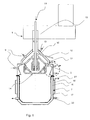
- the discharge of a biological paste obtained in the fractionation of human blood plasma is carried out from a centrifuge drum 14 with an outer diameter of 468 mm at a drum speed of 7000 l / min and deflection of the blood plasma paste by a Pasteumlenkring 4.
- the centrifuge 1 has a drive part 13 for driving the drum 14 with a supply line 11 for the plasma.
- the drum 14 is suspended in a separable lower part of the centrifuge 1, which comprises the jacket housing 10, with feed lines 19 and discharges 22 for a cooling liquid and feed lines 9 for liquid nitrogen, the deflection ring 4 and the collecting container 7.
- the receptacle has a cooling jacket 16 with leads 20 and leads 21 and welded transport tabs 18.
- the drum 14 also has an outlet 12 for the clarified liquid.
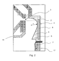
- Fig. 2 is the deflection ring 4 in detail again.
- the angle ⁇ above the opening width of the discharge slot 3 is also inclined by 15 ° to the horizontal, so that the impact surface 8 itself and the overlying area in the projection form a straight line.
- the discharged paste is deflected by a, viewed in longitudinal section, circular contour with a radius of curvature r of 45 ° in the direction of the container bottom of the collecting container 7.
- the Pasteumlenkring 5 has at its lower end a spoiler edge. 6
Landscapes
- Centrifugal Separators (AREA)
Claims (15)
- Centrifugeuse avec évacuation automatique pour le traitement technique de pâtes fortement concentrées, formée par un carter (10), apte à être refroidi le cas échéant, une conduite d'admission (11) pour la suspension, une conduite d'évacuation (12) pour le liquide filtré, un tambour (14) suspendu, relié à un élément d'entraînement (13) supérieur et muni de deux ou plusieurs fentes d'évacuation (3), et un collecteur (7), ladite centrifugeuse comportant, en outre, un anneau de déviation des pâtes, muni du déflecteur (2) annulaire, caractérisée en ce qu'un angle d'incidence α formé entre la tangente d'un déflecteur (2), situé en face des fentes d'évacuation, de l'anneau de déviation (4) et l'horizontale est de l'ordre de 3 à 60° par référence à la totalité de la largeur d'ouverture de la fente d'évacuation (3), et en ce que l'anneau de déviation est muni d'un système de refroidissement (8) de la paroi latérale.
- Centrifugeuse avec évacuation automatique selon la revendication 1, caractérisée en ce que le contour intérieur du déflecteur (2), directement en dessous de la surface de rebondissement, en particulier par référence à une coupe longitudinale quelconque de l'anneau de déviation des pâtes (4), est réalisé avec une forme circulaire ou en forme de parabole.
- Centrifugeuse avec évacuation automatique selon la revendication 2, caractérisée en ce que le déflecteur (2), dans la zone en dessous de la fente d'évacuation (3), possède un contour intérieur courbe par référence à une coupe longitudinale géométrique, avec un rayon de courbure supérieur à 20 mm, de préférence de 30 à 50 mm.
- Centrifugeuse avec évacuation automatique selon l'une quelconque des revendications 1 à 3, caractérisée en ce que la paroi de rebondissement (2), dans la zone au-dessus de la largeur d'ouverture de la fente d'évacuation (3), forme avec l'horizontale un angle d'incidence de 3 à 30°, de préférence de 5 à 15°.
- Centrifugeuse avec évacuation automatique selon l'une quelconque des revendications 1 à 4, caractérisée en ce que la tangente du contour intérieur de la surface de déflection (5), dans la zone en dessous du contour de déviation de l'anneau de déviation des pâtes (4), forme avec la verticale, par référence à une coupe longitudinale géométrique, un angle d'incidence β jusqu'à 30°, de préférence de 5 à 15°.
- Centrifugeuse avec évacuation automatique selon l'une quelconque des revendications 1 à 5, caractérisée en ce que l'anneau de déviation des pâtes (4) comporte, au niveau de son extrémité inférieure, un bord de rupture (6) qui, le cas échéant, est détalonné.
- Centrifugeuse avec évacuation automatique selon l'une quelconque des revendications 1 à 6, caractérisée en ce que l'anneau de déviation des pâtes (4) est relié d'un seul tenant à un collecteur ou de manière amovible au collecteur (7) de la centrifugeuse (1).
- Centrifugeuse avec évacuation automatique selon l'une quelconque des revendications 1 à 7, caractérisée en ce que la surface de l'anneau de déviation des pâtes (4), laquelle est en contact avec le produit, est munie d'un revêtement apte au glissement, réalisé en particulier en PTFE ou dans des alliages métalliques.
- Centrifugeuse avec évacuation automatique selon l'une quelconque des revendications 1 à 8, caractérisée en ce que l'anneau de déviation des pâtes (4) comporte une ou plusieurs buses (9) pour l'injection d'azote liquide.
- Centrifugeuse avec évacuation automatique selon l'une quelconque des revendications 1 à 9, caractérisée en ce que le collecteur (7) est réalisé sous forme cylindrique ou en se rétrécissant de manière conique vers le bas.
- Centrifugeuse avec évacuation automatique selon l'une quelconque des revendications 1 à 10, caractérisée en ce que les surfaces intérieures du collecteur (7), lesquelles sont en contact avec le produit, sont munies d'un revêtement apte au glissement, réalisé en particulier en PTFE ou dans des alliages métalliques.
- Centrifugeuse avec évacuation automatique selon l'une quelconque des revendications 1 à 11, caractérisée en ce qu'une poche (17) en matériau flexible est introduite dans le collecteur (7) et peut être immobilisée contre les parois du récipient en particulier au moyen d'une dépression.
- Centrifugeuse avec évacuation automatique selon l'une quelconque des revendications 1 à 12, caractérisée en ce que le collecteur (7) est équipé d'un système de réglage de la température (16), en particulier avec un système de refroidissement de paroi latérale.
- Centrifugeuse avec évacuation automatique selon l'une quelconque des revendications 1 à 13, caractérisée en ce que le collecteur (7) comporte des moyens (18) supplémentaires pour un transport, en particulier au moyen de systèmes à chariots de manutention.
- Centrifugeuse avec évacuation automatique selon l'une quelconque des revendications 1 à 14, caractérisée en ce que l'ouverture supérieure du collecteur (7) est réalisée sous la forme d'un collet partiel.
Applications Claiming Priority (3)
| Application Number | Priority Date | Filing Date | Title |
|---|---|---|---|
| DE10135317A DE10135317A1 (de) | 2001-07-19 | 2001-07-19 | Umlenkring für eine selbstaustragende Zentrifuge |
| DE10135317 | 2001-07-19 | ||
| PCT/EP2002/007563 WO2003008105A1 (fr) | 2001-07-19 | 2002-07-08 | Anneau de deviation pour centrifugeuse autodeverseuse |
Publications (3)
| Publication Number | Publication Date |
|---|---|
| EP1414582A1 EP1414582A1 (fr) | 2004-05-06 |
| EP1414582B1 true EP1414582B1 (fr) | 2010-03-10 |
| EP1414582B2 EP1414582B2 (fr) | 2016-07-20 |
Family
ID=7692447
Family Applications (1)
| Application Number | Title | Priority Date | Filing Date |
|---|---|---|---|
| EP02747462.6A Expired - Lifetime EP1414582B2 (fr) | 2001-07-19 | 2002-07-08 | Anneau de deviation pour centrifugeuse autodeverseuse |
Country Status (9)
| Country | Link |
|---|---|
| US (1) | US7204795B2 (fr) |
| EP (1) | EP1414582B2 (fr) |
| JP (1) | JP4301939B2 (fr) |
| CN (1) | CN1290622C (fr) |
| AT (1) | ATE460229T1 (fr) |
| CA (1) | CA2453975C (fr) |
| DE (2) | DE10135317A1 (fr) |
| DK (1) | DK1414582T4 (fr) |
| WO (1) | WO2003008105A1 (fr) |
Families Citing this family (19)
| Publication number | Priority date | Publication date | Assignee | Title |
|---|---|---|---|---|
| DE10103769C2 (de) * | 2001-01-27 | 2003-07-31 | Westfalia Separator Food Tec G | Zentrifuge |
| DE10135317A1 (de) * | 2001-07-19 | 2003-01-30 | Bayer Ag | Umlenkring für eine selbstaustragende Zentrifuge |
| DE10139466A1 (de) * | 2001-08-10 | 2003-02-20 | Bayer Ag | Verfahren zur Abtrennung von Blutplasmapartikeln aus einer Blutplasmasuspension |
| CN101310180B (zh) | 2005-11-18 | 2013-05-08 | 乌斯特技术股份公司 | 一种测量花纱特征的方法 |
| SE533562C2 (sv) | 2009-03-06 | 2010-10-26 | Alfa Laval Corp Ab | Centrifugalseparator |
| CN101544458B (zh) * | 2009-05-05 | 2010-12-29 | 宫能和 | 高效泥浆处理机 |
| US8870733B2 (en) | 2010-11-19 | 2014-10-28 | Kensey Nash Corporation | Centrifuge |
| US8394006B2 (en) | 2010-11-19 | 2013-03-12 | Kensey Nash Corporation | Centrifuge |
| US8556794B2 (en) | 2010-11-19 | 2013-10-15 | Kensey Nash Corporation | Centrifuge |
| US8317672B2 (en) | 2010-11-19 | 2012-11-27 | Kensey Nash Corporation | Centrifuge method and apparatus |
| US8469871B2 (en) | 2010-11-19 | 2013-06-25 | Kensey Nash Corporation | Centrifuge |
| US20220031925A1 (en) | 2010-11-19 | 2022-02-03 | Dsm Ip Assets B.V. | Centrifuge |
| CN102319640A (zh) * | 2011-06-16 | 2012-01-18 | 安徽赛而特离心机有限公司 | 一种碟式分离机的机身 |
| CN102911076B (zh) * | 2012-11-07 | 2015-09-02 | 河北冀衡(集团)药业有限公司 | 对乙酰氨基酚精制后的处理装置及其处理方法 |
| CN106413904A (zh) | 2014-01-31 | 2017-02-15 | 帝斯曼知识产权资产管理有限公司 | 脂肪组织离心装置和使用方法 |
| DE102017106801B3 (de) | 2017-03-29 | 2018-08-02 | Gea Mechanical Equipment Gmbh | Selbstentleerender Separator zum schonenden Austrag von scherempfindlichen Produkten sowie Verfahren zu seinem Betrieb |
| DE102017113583A1 (de) * | 2017-06-20 | 2018-12-20 | Bluecatbio Gmbh | Zentrifuge |
| CN108097478B (zh) * | 2018-01-31 | 2024-01-26 | 浙江轻机离心机制造有限公司 | 防止乳胶浓缩分离过程粘结的转鼓芯部冷却装置 |
| CN112403690B (zh) * | 2019-08-22 | 2022-06-10 | 晨光生物科技集团股份有限公司 | 一种防爆卧式离心机 |
Family Cites Families (32)
| Publication number | Priority date | Publication date | Assignee | Title |
|---|---|---|---|---|
| US1762899A (en) * | 1927-07-04 | 1930-06-10 | John Winsloe | Machine for separating solids from liquids |
| US2628021A (en) * | 1949-05-03 | 1953-02-10 | Separator Ab | Centrifuge with auxiliary feed arrangement |
| US2668658A (en) † | 1950-03-08 | 1954-02-09 | Merco Centrifugal Co | Centrifuge machine |
| US2723799A (en) * | 1951-02-03 | 1955-11-15 | Sharples Corp | Centrifugal separation |
| US2724549A (en) * | 1951-04-09 | 1955-11-22 | Clarence J Brown | Centrifugal separator and method of operating the same |
| GB853783A (en) † | 1958-01-21 | 1960-11-09 | Henri Morren | New piperazine derivatives and process for the preparation thereof |
| CH380030A (de) † | 1959-09-10 | 1964-07-15 | Westfalia Separator Ag | Düsenzentrifuge zum Trennen von Quark und Molke |
| US3204868A (en) * | 1960-06-06 | 1965-09-07 | Dorr Oliver Inc | Three-product nozzle-type centrifuge |
| DE2260461C3 (de) * | 1972-12-11 | 1980-06-04 | Krauss-Maffei Ag, 8000 Muenchen | Filterzentrifuge |
| US3799431A (en) * | 1973-01-17 | 1974-03-26 | Pennwalt Corp | Centrifuge apparatus |
| DE2423319C3 (de) * | 1974-05-14 | 1976-10-14 | Westfalia Separator Ag | Zentrifuge mit einer zylindrischen vollwandigen schleudertrommel, deren mantel durch ein im kreislauf gefuehrtes erstes kuehlmedium kontinuierlich kuehlbar ist |
| DE2631110C3 (de) † | 1976-07-10 | 1980-09-04 | Westfalia Separator Ag, 4740 Oelde | Selbstreinigende Schleudertrommel |
| DE2916856A1 (de) * | 1979-04-26 | 1980-11-06 | Hoechst Ag | Separator |
| EP0031549A1 (fr) * | 1979-12-20 | 1981-07-08 | Verenigde Machinefabrieken Stork N.V. | Centrifugeur à marche continue |
| US4289270A (en) † | 1980-02-19 | 1981-09-15 | Jack G. Riley | Portable concentrator |
| US4286748A (en) * | 1980-05-19 | 1981-09-01 | Bailey Albert C | Centrifugal concentrator |
| DE3802305C1 (en) | 1988-01-27 | 1989-10-05 | Westfalia Separator Ag, 4740 Oelde, De | Process and apparatus for the centrifugal removal of bacteria from milk |
| WO1992011947A1 (fr) * | 1991-01-14 | 1992-07-23 | W.D.T. (Engineers) Pty. Ltd. | Deflecteur centrifuge de solides |
| US5269849A (en) * | 1992-06-25 | 1993-12-14 | Silver-Weibull | Apparatus and method for reducing lump formation and crystal impact damage in a sugar centrifugal |
| US5713827A (en) * | 1992-07-08 | 1998-02-03 | Trylock Pty Ltd | Centrifugal filter device |
| US5368541A (en) * | 1993-06-03 | 1994-11-29 | Knelson; Benjamin V. | Method of extraction of mercury and gold from mine tailings |
| AUPM376094A0 (en) | 1994-02-08 | 1994-03-03 | Stg Holdings Pty Ltd | Centrifugal separations apparatus |
| US5788621A (en) * | 1994-06-23 | 1998-08-04 | Eady; Robert Ernest Charles | Method and apparatus for centrifugal separation of solids from mud and compaction |
| SE513831C2 (sv) * | 1998-02-27 | 2000-11-13 | Alfa Laval Ab | Centrifugalseparator |
| SE9802116D0 (sv) † | 1998-06-15 | 1998-06-15 | Alfa Laval Ab | Dekantercentrifug |
| DE19846535C2 (de) | 1998-10-09 | 2000-12-07 | Westfalia Separator Ag | Zentrifuge |
| US6036630A (en) * | 1999-03-26 | 2000-03-14 | Praxair Technology, Inc. | Centrifugal extraction process |
| DE19948118C2 (de) † | 1999-10-06 | 2002-06-27 | Flottweg Gmbh | Separator mit abgeschirmter Trommel |
| CN1104957C (zh) * | 2001-02-13 | 2003-04-09 | 黄敏彦 | 离心泥水分离机 |
| DE10135317A1 (de) * | 2001-07-19 | 2003-01-30 | Bayer Ag | Umlenkring für eine selbstaustragende Zentrifuge |
| DE10139466A1 (de) * | 2001-08-10 | 2003-02-20 | Bayer Ag | Verfahren zur Abtrennung von Blutplasmapartikeln aus einer Blutplasmasuspension |
| DE10220757B4 (de) * | 2002-05-08 | 2004-06-24 | Westfalia Separator Ag | Zentrifuge, insbesondere Separator |
-
2001
- 2001-07-19 DE DE10135317A patent/DE10135317A1/de not_active Withdrawn
-
2002
- 2002-07-08 DK DK02747462.6T patent/DK1414582T4/da active
- 2002-07-08 AT AT02747462T patent/ATE460229T1/de active
- 2002-07-08 JP JP2003513702A patent/JP4301939B2/ja not_active Expired - Fee Related
- 2002-07-08 US US10/482,547 patent/US7204795B2/en not_active Expired - Lifetime
- 2002-07-08 CN CN02814480.5A patent/CN1290622C/zh not_active Expired - Fee Related
- 2002-07-08 WO PCT/EP2002/007563 patent/WO2003008105A1/fr not_active Ceased
- 2002-07-08 DE DE50214269T patent/DE50214269D1/de not_active Expired - Lifetime
- 2002-07-08 CA CA2453975A patent/CA2453975C/fr not_active Expired - Fee Related
- 2002-07-08 EP EP02747462.6A patent/EP1414582B2/fr not_active Expired - Lifetime
Also Published As
| Publication number | Publication date |
|---|---|
| EP1414582A1 (fr) | 2004-05-06 |
| JP2004534652A (ja) | 2004-11-18 |
| JP4301939B2 (ja) | 2009-07-22 |
| DK1414582T4 (da) | 2016-11-14 |
| HK1069141A1 (en) | 2005-05-13 |
| US7204795B2 (en) | 2007-04-17 |
| CA2453975A1 (fr) | 2003-01-30 |
| US20040176233A1 (en) | 2004-09-09 |
| ATE460229T1 (de) | 2010-03-15 |
| CN1533307A (zh) | 2004-09-29 |
| DE10135317A1 (de) | 2003-01-30 |
| EP1414582B2 (fr) | 2016-07-20 |
| CN1290622C (zh) | 2006-12-20 |
| DK1414582T3 (da) | 2010-06-21 |
| CA2453975C (fr) | 2010-01-26 |
| DE50214269D1 (de) | 2010-04-22 |
| WO2003008105A1 (fr) | 2003-01-30 |
Similar Documents
| Publication | Publication Date | Title |
|---|---|---|
| EP1414582B2 (fr) | Anneau de deviation pour centrifugeuse autodeverseuse | |
| EP0454045A2 (fr) | Appareil de séchage centrifuge | |
| DE102016112112B4 (de) | Zentrifugalfiltervorrichtung | |
| EP0195826A1 (fr) | Mélangeur, dispositif de sédimentation etc. pour liquides contenant des particules | |
| EP0322516A2 (fr) | Centrifuge à bol plein | |
| EP1345700A1 (fr) | Centrifugeuse a vis, a bol plein, a assiettes | |
| DE4414750C2 (de) | Verfahren und Vorrichtung zum Reinigen viskoser Kunststoffschmelzen | |
| EP0536650B1 (fr) | Procédé et dispositif pour sècher des substances humides | |
| DE2707111B2 (de) | Vollmantel-Schneckenzentrifuge zur Trennung eines Feststoff-Flüssigkeitsgemisches | |
| EP0524455B1 (fr) | Centrifugeuse | |
| US7122118B2 (en) | Apparatus for treatment of contaminated liquids | |
| DE4425906A1 (de) | Naßmahlsystem | |
| US20030224920A1 (en) | Rotating-machine bowl assembly with flow guide | |
| DE2851533A1 (de) | Kohlevergasungsanlage | |
| JP2775141B2 (ja) | スクリュープレス式固液分離装置 | |
| EP1228808B1 (fr) | Dispositif et méthode pour racler et évacuer le gateau solide d'une centifugeuse | |
| EP1228807A1 (fr) | Dispositif pour racler le gateau solide d'une centrifugeuse | |
| WO2026021936A1 (fr) | Ensemble d'inserts de séparateur pour séparateur | |
| DE4234636C2 (de) | Vorrichtung und Verfahren zur nassmechanischen Trennung/Sortierung von Kunststoffgemischen | |
| WO2003089111A1 (fr) | Dispositif de filtration a systeme de separation par centrifugation integre | |
| DE19810323A1 (de) | Schubzentrifuge für Suspensionen mit niedrigem Feststoffgehalt | |
| DE2621349A1 (de) | Verfahren und vorrichtung zur kontinuierlichen trennung der festen phase von der fluessigen phase eines feststoff-fluessigkeits-gemisches | |
| HK1069141B (en) | Self-distributing centrifuge and its deviation ring | |
| EP1787723B1 (fr) | Cartouche centrifuge | |
| DE2262870C3 (de) | Reinigungszentrifuge zur Trennung von Feststoffen aus Flüssigkeiten |
Legal Events
| Date | Code | Title | Description |
|---|---|---|---|
| PUAI | Public reference made under article 153(3) epc to a published international application that has entered the european phase |
Free format text: ORIGINAL CODE: 0009012 |
|
| 17P | Request for examination filed |
Effective date: 20040219 |
|
| AK | Designated contracting states |
Kind code of ref document: A1 Designated state(s): AT BE CH CY DE DK ES FI FR GB GR IE IT LI LU MC NL PT SE TR |
|
| AX | Request for extension of the european patent |
Extension state: AL LT LV MK RO SI |
|
| RAP1 | Party data changed (applicant data changed or rights of an application transferred) |
Owner name: WESTFALIA SEPARATOR AG |
|
| 17Q | First examination report despatched |
Effective date: 20080411 |
|
| RAP1 | Party data changed (applicant data changed or rights of an application transferred) |
Owner name: WESTFALIA SEPARATOR GMBH |
|
| RAP1 | Party data changed (applicant data changed or rights of an application transferred) |
Owner name: GEA WESTFALIA SEPARATOR GMBH |
|
| GRAP | Despatch of communication of intention to grant a patent |
Free format text: ORIGINAL CODE: EPIDOSNIGR1 |
|
| GRAS | Grant fee paid |
Free format text: ORIGINAL CODE: EPIDOSNIGR3 |
|
| GRAA | (expected) grant |
Free format text: ORIGINAL CODE: 0009210 |
|
| AK | Designated contracting states |
Kind code of ref document: B1 Designated state(s): AT BE CH CY DE DK ES FI FR GB GR IE IT LI LU MC NL PT SE TR |
|
| REG | Reference to a national code |
Ref country code: GB Ref legal event code: FG4D Free format text: NOT ENGLISH |
|
| REG | Reference to a national code |
Ref country code: CH Ref legal event code: EP |
|
| REG | Reference to a national code |
Ref country code: IE Ref legal event code: FG4D |
|
| REF | Corresponds to: |
Ref document number: 50214269 Country of ref document: DE Date of ref document: 20100422 Kind code of ref document: P |
|
| REG | Reference to a national code |
Ref country code: DK Ref legal event code: T3 |
|
| REG | Reference to a national code |
Ref country code: NL Ref legal event code: VDEP Effective date: 20100310 |
|
| PG25 | Lapsed in a contracting state [announced via postgrant information from national office to epo] |
Ref country code: FI Free format text: LAPSE BECAUSE OF FAILURE TO SUBMIT A TRANSLATION OF THE DESCRIPTION OR TO PAY THE FEE WITHIN THE PRESCRIBED TIME-LIMIT Effective date: 20100310 |
|
| REG | Reference to a national code |
Ref country code: IE Ref legal event code: FD4D |
|
| PG25 | Lapsed in a contracting state [announced via postgrant information from national office to epo] |
Ref country code: ES Free format text: LAPSE BECAUSE OF FAILURE TO SUBMIT A TRANSLATION OF THE DESCRIPTION OR TO PAY THE FEE WITHIN THE PRESCRIBED TIME-LIMIT Effective date: 20100621 Ref country code: CY Free format text: LAPSE BECAUSE OF FAILURE TO SUBMIT A TRANSLATION OF THE DESCRIPTION OR TO PAY THE FEE WITHIN THE PRESCRIBED TIME-LIMIT Effective date: 20100310 Ref country code: NL Free format text: LAPSE BECAUSE OF FAILURE TO SUBMIT A TRANSLATION OF THE DESCRIPTION OR TO PAY THE FEE WITHIN THE PRESCRIBED TIME-LIMIT Effective date: 20100310 Ref country code: SE Free format text: LAPSE BECAUSE OF FAILURE TO SUBMIT A TRANSLATION OF THE DESCRIPTION OR TO PAY THE FEE WITHIN THE PRESCRIBED TIME-LIMIT Effective date: 20100310 Ref country code: GR Free format text: LAPSE BECAUSE OF FAILURE TO SUBMIT A TRANSLATION OF THE DESCRIPTION OR TO PAY THE FEE WITHIN THE PRESCRIBED TIME-LIMIT Effective date: 20100611 |
|
| PLBI | Opposition filed |
Free format text: ORIGINAL CODE: 0009260 |
|
| PLAX | Notice of opposition and request to file observation + time limit sent |
Free format text: ORIGINAL CODE: EPIDOSNOBS2 |
|
| 26 | Opposition filed |
Opponent name: ALFA LAVAL CORPORATE AB Effective date: 20101209 |
|
| BERE | Be: lapsed |
Owner name: GEA WESTFALIA SEPARATOR G.M.B.H. Effective date: 20100731 |
|
| PG25 | Lapsed in a contracting state [announced via postgrant information from national office to epo] |
Ref country code: IE Free format text: LAPSE BECAUSE OF FAILURE TO SUBMIT A TRANSLATION OF THE DESCRIPTION OR TO PAY THE FEE WITHIN THE PRESCRIBED TIME-LIMIT Effective date: 20100310 Ref country code: PT Free format text: LAPSE BECAUSE OF FAILURE TO SUBMIT A TRANSLATION OF THE DESCRIPTION OR TO PAY THE FEE WITHIN THE PRESCRIBED TIME-LIMIT Effective date: 20100712 |
|
| PG25 | Lapsed in a contracting state [announced via postgrant information from national office to epo] |
Ref country code: MC Free format text: LAPSE BECAUSE OF NON-PAYMENT OF DUE FEES Effective date: 20100731 |
|
| REG | Reference to a national code |
Ref country code: CH Ref legal event code: PL |
|
| GBPC | Gb: european patent ceased through non-payment of renewal fee |
Effective date: 20100708 |
|
| PG25 | Lapsed in a contracting state [announced via postgrant information from national office to epo] |
Ref country code: IT Free format text: LAPSE BECAUSE OF FAILURE TO SUBMIT A TRANSLATION OF THE DESCRIPTION OR TO PAY THE FEE WITHIN THE PRESCRIBED TIME-LIMIT Effective date: 20100310 |
|
| REG | Reference to a national code |
Ref country code: FR Ref legal event code: ST Effective date: 20110331 |
|
| PG25 | Lapsed in a contracting state [announced via postgrant information from national office to epo] |
Ref country code: CH Free format text: LAPSE BECAUSE OF NON-PAYMENT OF DUE FEES Effective date: 20100731 Ref country code: LI Free format text: LAPSE BECAUSE OF NON-PAYMENT OF DUE FEES Effective date: 20100731 |
|
| PLAF | Information modified related to communication of a notice of opposition and request to file observations + time limit |
Free format text: ORIGINAL CODE: EPIDOSCOBS2 |
|
| PG25 | Lapsed in a contracting state [announced via postgrant information from national office to epo] |
Ref country code: FR Free format text: LAPSE BECAUSE OF NON-PAYMENT OF DUE FEES Effective date: 20100802 |
|
| PG25 | Lapsed in a contracting state [announced via postgrant information from national office to epo] |
Ref country code: BE Free format text: LAPSE BECAUSE OF NON-PAYMENT OF DUE FEES Effective date: 20100731 |
|
| PLBB | Reply of patent proprietor to notice(s) of opposition received |
Free format text: ORIGINAL CODE: EPIDOSNOBS3 |
|
| PG25 | Lapsed in a contracting state [announced via postgrant information from national office to epo] |
Ref country code: GB Free format text: LAPSE BECAUSE OF NON-PAYMENT OF DUE FEES Effective date: 20100708 |
|
| PG25 | Lapsed in a contracting state [announced via postgrant information from national office to epo] |
Ref country code: LU Free format text: LAPSE BECAUSE OF NON-PAYMENT OF DUE FEES Effective date: 20100708 |
|
| PG25 | Lapsed in a contracting state [announced via postgrant information from national office to epo] |
Ref country code: TR Free format text: LAPSE BECAUSE OF FAILURE TO SUBMIT A TRANSLATION OF THE DESCRIPTION OR TO PAY THE FEE WITHIN THE PRESCRIBED TIME-LIMIT Effective date: 20100310 |
|
| PLCK | Communication despatched that opposition was rejected |
Free format text: ORIGINAL CODE: EPIDOSNREJ1 |
|
| APAH | Appeal reference modified |
Free format text: ORIGINAL CODE: EPIDOSCREFNO |
|
| APBM | Appeal reference recorded |
Free format text: ORIGINAL CODE: EPIDOSNREFNO |
|
| APBP | Date of receipt of notice of appeal recorded |
Free format text: ORIGINAL CODE: EPIDOSNNOA2O |
|
| APBQ | Date of receipt of statement of grounds of appeal recorded |
Free format text: ORIGINAL CODE: EPIDOSNNOA3O |
|
| APBU | Appeal procedure closed |
Free format text: ORIGINAL CODE: EPIDOSNNOA9O |
|
| PUAH | Patent maintained in amended form |
Free format text: ORIGINAL CODE: 0009272 |
|
| STAA | Information on the status of an ep patent application or granted ep patent |
Free format text: STATUS: PATENT MAINTAINED AS AMENDED |
|
| 27A | Patent maintained in amended form |
Effective date: 20160720 |
|
| AK | Designated contracting states |
Kind code of ref document: B2 Designated state(s): AT BE CH CY DE DK ES FI FR GB GR IE IT LI LU MC NL PT SE TR |
|
| REG | Reference to a national code |
Ref country code: DE Ref legal event code: R102 Ref document number: 50214269 Country of ref document: DE |
|
| REG | Reference to a national code |
Ref country code: DK Ref legal event code: T4 Effective date: 20161108 |
|
| PGFP | Annual fee paid to national office [announced via postgrant information from national office to epo] |
Ref country code: DK Payment date: 20190725 Year of fee payment: 18 Ref country code: DE Payment date: 20190805 Year of fee payment: 18 |
|
| PGFP | Annual fee paid to national office [announced via postgrant information from national office to epo] |
Ref country code: AT Payment date: 20190723 Year of fee payment: 18 |
|
| REG | Reference to a national code |
Ref country code: DE Ref legal event code: R119 Ref document number: 50214269 Country of ref document: DE |
|
| REG | Reference to a national code |
Ref country code: DK Ref legal event code: EBP Effective date: 20200731 |
|
| REG | Reference to a national code |
Ref country code: AT Ref legal event code: MM01 Ref document number: 460229 Country of ref document: AT Kind code of ref document: T Effective date: 20200708 |
|
| PG25 | Lapsed in a contracting state [announced via postgrant information from national office to epo] |
Ref country code: AT Free format text: LAPSE BECAUSE OF NON-PAYMENT OF DUE FEES Effective date: 20200708 Ref country code: DE Free format text: LAPSE BECAUSE OF NON-PAYMENT OF DUE FEES Effective date: 20210202 |
|
| PG25 | Lapsed in a contracting state [announced via postgrant information from national office to epo] |
Ref country code: DK Free format text: LAPSE BECAUSE OF NON-PAYMENT OF DUE FEES Effective date: 20200731 |