EP1414654B1 - Luftreifen zum ausgleich von restausrichtungsdrehmoment und verfahren zu seiner herstellung - Google Patents
Luftreifen zum ausgleich von restausrichtungsdrehmoment und verfahren zu seiner herstellung Download PDFInfo
- Publication number
- EP1414654B1 EP1414654B1 EP02763287A EP02763287A EP1414654B1 EP 1414654 B1 EP1414654 B1 EP 1414654B1 EP 02763287 A EP02763287 A EP 02763287A EP 02763287 A EP02763287 A EP 02763287A EP 1414654 B1 EP1414654 B1 EP 1414654B1
- Authority
- EP
- European Patent Office
- Prior art keywords
- sipe
- tire
- tread
- sipes
- inclination
- Prior art date
- Legal status (The legal status is an assumption and is not a legal conclusion. Google has not performed a legal analysis and makes no representation as to the accuracy of the status listed.)
- Expired - Lifetime
Links
- 238000004519 manufacturing process Methods 0.000 title claims description 4
- 238000000034 method Methods 0.000 claims abstract description 10
- 238000005266 casting Methods 0.000 claims 1
- 238000005094 computer simulation Methods 0.000 claims 1
- 238000004088 simulation Methods 0.000 claims 1
- 238000012360 testing method Methods 0.000 description 11
- 230000000694 effects Effects 0.000 description 7
- 238000010276 construction Methods 0.000 description 2
- 238000000465 moulding Methods 0.000 description 2
- 238000005096 rolling process Methods 0.000 description 2
- 101100334009 Caenorhabditis elegans rib-2 gene Proteins 0.000 description 1
- 238000004458 analytical method Methods 0.000 description 1
- 230000003466 anti-cipated effect Effects 0.000 description 1
- 230000015572 biosynthetic process Effects 0.000 description 1
- 150000001875 compounds Chemical class 0.000 description 1
- 238000012937 correction Methods 0.000 description 1
- 230000001419 dependent effect Effects 0.000 description 1
- 239000000463 material Substances 0.000 description 1
- 239000002184 metal Substances 0.000 description 1
- 230000035945 sensitivity Effects 0.000 description 1
Images


Classifications
-
- B—PERFORMING OPERATIONS; TRANSPORTING
- B60—VEHICLES IN GENERAL
- B60C—VEHICLE TYRES; TYRE INFLATION; TYRE CHANGING; CONNECTING VALVES TO INFLATABLE ELASTIC BODIES IN GENERAL; DEVICES OR ARRANGEMENTS RELATED TO TYRES
- B60C11/00—Tyre tread bands; Tread patterns; Anti-skid inserts
- B60C11/03—Tread patterns
- B60C11/12—Tread patterns characterised by the use of narrow slits or incisions, e.g. sipes
-
- B—PERFORMING OPERATIONS; TRANSPORTING
- B60—VEHICLES IN GENERAL
- B60C—VEHICLE TYRES; TYRE INFLATION; TYRE CHANGING; CONNECTING VALVES TO INFLATABLE ELASTIC BODIES IN GENERAL; DEVICES OR ARRANGEMENTS RELATED TO TYRES
- B60C11/00—Tyre tread bands; Tread patterns; Anti-skid inserts
- B60C11/03—Tread patterns
- B60C11/11—Tread patterns in which the raised area of the pattern consists only of isolated elements, e.g. blocks
-
- B—PERFORMING OPERATIONS; TRANSPORTING
- B60—VEHICLES IN GENERAL
- B60C—VEHICLE TYRES; TYRE INFLATION; TYRE CHANGING; CONNECTING VALVES TO INFLATABLE ELASTIC BODIES IN GENERAL; DEVICES OR ARRANGEMENTS RELATED TO TYRES
- B60C11/00—Tyre tread bands; Tread patterns; Anti-skid inserts
- B60C11/03—Tread patterns
- B60C11/12—Tread patterns characterised by the use of narrow slits or incisions, e.g. sipes
- B60C11/1236—Tread patterns characterised by the use of narrow slits or incisions, e.g. sipes with special arrangements in the tread pattern
- B60C11/124—Tread patterns characterised by the use of narrow slits or incisions, e.g. sipes with special arrangements in the tread pattern inclined with regard to a plane normal to the tread surface
-
- B—PERFORMING OPERATIONS; TRANSPORTING
- B29—WORKING OF PLASTICS; WORKING OF SUBSTANCES IN A PLASTIC STATE IN GENERAL
- B29D—PRODUCING PARTICULAR ARTICLES FROM PLASTICS OR FROM SUBSTANCES IN A PLASTIC STATE
- B29D30/00—Producing pneumatic or solid tyres or parts thereof
- B29D30/06—Pneumatic tyres or parts thereof (e.g. produced by casting, moulding, compression moulding, injection moulding, centrifugal casting)
- B29D30/0601—Vulcanising tyres; Vulcanising presses for tyres
- B29D30/0606—Vulcanising moulds not integral with vulcanising presses
- B29D2030/0607—Constructional features of the moulds
- B29D2030/0613—Means, e.g. sipes or blade-like elements, for forming narrow recesses in the tyres, e.g. cuts or incisions for winter tyres
-
- B—PERFORMING OPERATIONS; TRANSPORTING
- B60—VEHICLES IN GENERAL
- B60C—VEHICLE TYRES; TYRE INFLATION; TYRE CHANGING; CONNECTING VALVES TO INFLATABLE ELASTIC BODIES IN GENERAL; DEVICES OR ARRANGEMENTS RELATED TO TYRES
- B60C11/00—Tyre tread bands; Tread patterns; Anti-skid inserts
- B60C11/03—Tread patterns
- B60C11/12—Tread patterns characterised by the use of narrow slits or incisions, e.g. sipes
- B60C11/1204—Tread patterns characterised by the use of narrow slits or incisions, e.g. sipes with special shape of the sipe
- B60C2011/1213—Tread patterns characterised by the use of narrow slits or incisions, e.g. sipes with special shape of the sipe sinusoidal or zigzag at the tread surface
-
- Y—GENERAL TAGGING OF NEW TECHNOLOGICAL DEVELOPMENTS; GENERAL TAGGING OF CROSS-SECTIONAL TECHNOLOGIES SPANNING OVER SEVERAL SECTIONS OF THE IPC; TECHNICAL SUBJECTS COVERED BY FORMER USPC CROSS-REFERENCE ART COLLECTIONS [XRACs] AND DIGESTS
- Y10—TECHNICAL SUBJECTS COVERED BY FORMER USPC
- Y10S—TECHNICAL SUBJECTS COVERED BY FORMER USPC CROSS-REFERENCE ART COLLECTIONS [XRACs] AND DIGESTS
- Y10S152/00—Resilient tires and wheels
- Y10S152/03—Slits in threads
-
- Y—GENERAL TAGGING OF NEW TECHNOLOGICAL DEVELOPMENTS; GENERAL TAGGING OF CROSS-SECTIONAL TECHNOLOGIES SPANNING OVER SEVERAL SECTIONS OF THE IPC; TECHNICAL SUBJECTS COVERED BY FORMER USPC CROSS-REFERENCE ART COLLECTIONS [XRACs] AND DIGESTS
- Y10—TECHNICAL SUBJECTS COVERED BY FORMER USPC
- Y10S—TECHNICAL SUBJECTS COVERED BY FORMER USPC CROSS-REFERENCE ART COLLECTIONS [XRACs] AND DIGESTS
- Y10S152/00—Resilient tires and wheels
- Y10S152/902—Non-directional tread pattern having no circumferential rib and having blocks defined by circumferential grooves and transverse grooves
Definitions
- Another preferred feature of the invention is the ability to make changes in the residual aligning torque (RAT) without changing the carcass or road contacting tread pattern by forming the tire tread blocks with angled sipes extending in the fore and aft directions in opposing ribs of the tire tread pattern.
- RAT residual aligning torque
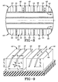
- Fig. 1 is a plan view of a portion of a pneumatic tread pattern indicated generally at 1, which includes a pair of shoulder ribs 2, a pair of intermediate ribs 3 and 4 and a center rib 5.
- Each rib 2 is formed by a plurality of tread blocks 6 separated by generally V-shaped grooves 7. If desired grooves 7 could be continuously curved or have multiple angles in addition to the double angle of the V-shape groove as shown.
- Each intermediate rib 3 and 4 is formed by a plurality of tread blocks 9 separated by laterally extending grooves 10.
- Center rib 5 is formed by a plurality of circumferentially spaced tread blocks 12 separated by lateral grooves 13.
- the FEA calculations showed that the projected sensitivity to the sipe inclination angle is about 0.37 N-m/o inclination angle.
- the actual measured change in RAT obtained from the test results in Chart Two showed a change in RAT of 0.28 N-m /o inclination angle. It is believed that the main reason for the difference between the model affect and the actual affect on the test tires is in the material properties of the tread compound and the loading corrections on the tire.
- the test results show there is a definite change in RAT by providing angled sipes in the tread blocks and that various changes in RAT can be achieved by varying the sipe angle and that the amount of desired change in RAT can be determined to some degree of certainty by FEA as set forth in Chart One.
Landscapes
- Engineering & Computer Science (AREA)
- Mechanical Engineering (AREA)
- Tires In General (AREA)
Claims (11)
- Ein Luftreifen, umfassend:ein sich dem Umfang nach erstreckendes Profilmuster (1; 24; 27) mit sich dem Umfang nach erstreckenden Rippen (2, 3, 4; 43), wobei die Rippen an gegenüberliegenden Seiten einer Mittenumfangsebene (15) des Reifens positioniert sind;eine Vielzahl von Profilblöcken (6, 9; 42) in mindestens einigen der sich dem Umfang nach erstreckenden Rippen (2, 3, 4; 43), wobei die Profilblöcke (6, 9; 42) durch sich lateral erstreckende Rillen (7, 10; 44) getrennt sind;eine gewinkelte Lamelle (17, 18; 25, 26; 28, 29; 33, 34; 40), die in mindestens einigen der Profilblöcke ausgebildet ist, wobei sich jede Lamelle über eine laterale Lamellenbreite (W) und eine radiale Lamellentiefe (D) mit einem Lamellenneigungswinkel (A) zwischen 2° und 15° in Bezug auf eine radiale Ebene (20) erstreckt, die durch eine äußerste Profilfläche des Profilblocks (6, 9; 42) und benachbart zu der Lamelle (17, 18; 25, 26; 28, 29; 33, 34; 40) und durch eine Drehachse des Reifens verläuft,dadurch gekennzeichnet, dasssich jede Lamelle (17; 25; 28; 33; 40) in sich dem Umfang nach erstreckenden Rippen (2, 3, 4; 43) an einer ersten Seite der Mittenumfangsebene (15) mit einem ersten Lamellenneigungswinkel (A) in Bezug auf die radiale Ebene (20) über die laterale Lamellenbreite (W) und die radiale Lamellentiefe (D) erstreckt, und dadurch, dasssich jede Lamelle (18; 26; 29; 34; 40) in sich dem Umfang nach erstreckenden Rippen (2, 3, 4; 43) an einer zweiten Seite der Mittenumfangsebene mit einem zweiten Lamellenneigungswinkel (A) in Bezug auf die radiale Ebene (20), die im Wesentlichen gleich mit und gegenüberliegend zu dem ersten Lamellenneigungswinkel (A) ist, über die laterale Lamellenbreite (W) und die radiale Lamellentiefe (D) erstreckt,wobei die Profilblöcke (6, 9; 42) an gegenüberliegenden Seiten der Mittenumfangsebene eine Kraft an dem Reifen während einer lasttragenden Drehung des Reifens gegen eine Fläche erzeugen, wobei die Kraft Kräfte einschließt, die sich in gegenüberliegende Richtungen an gegenüberliegenden Seiten der Mittenumfangsebene (15) unter Erzeugung eines Gesamtmoments an dem Reifen erstrecken, um ein Restausrichtungsdrehmoment des Reifens herzustellen.
- Der in Anspruch 1 definierte Reifen, wobei der Lamellenneigungswinkel (A) 7° beträgt.
- Der in Anspruch 1 oder Anspruch 2 definierte Reifen, wobei die Lamellen (17, 18; 25, 26; 28, 29; 33, 34; 40) eine Tiefe zwischen 20 % und 100 % der Höhe der Profilblöcke (6, 9; 42) aufweisen.
- Der in einem der Ansprüche 1-3 definierte Reifen, wobei die Lamellen (17, 18; 40) im Wesentlichen senkrecht zu der Mittenumfangsebene (15) des Reifens sind.
- Der in einem der Ansprüche 1-3 definierte Reifen, wobei die Lamellen (25, 26) in einem Winkel in Bezug auf die Mittenumfangsebene (15) des Reifens ausgebildet sind.
- Der in einem der Ansprüche 1-5 definierte Reifen, wobei die Lamellen (17, 18; 25, 26; 28, 29; 33, 34; 40) jeweils eine Breite zwischen 0,038 mm bis 1,52 mm (0,015 Zoll und 0,06 Zoll) aufweisen.
- Der in einem der Ansprüche 1-3 oder 6 definierte Reifen, wobei die Lamellen (33, 34; 40) in entgegengesetzten Schulterrippen (2; 43) des Reifens ausgebildet sind.
- Der in einem der Ansprüche 1-6 definierte Reifen, wobei die Lamellen (17, 18; 25, 26; 28, 29) in entgegengesetzten Zwischenrippen (3, 4) des Reifens ausgebildet sind.
- Der in einem der Ansprüche 1-3, 5, 6 oder 8 definierte Reifen, wobei sich die Lamellen (25, 26) teilweise über die laterale Breite der Profilblöcke (3, 4) erstrecken.
- Der in einem der Ansprüche 1-9 definierte Reifen, wobei eine Vielzahl der Lamellen (17, 18; 25, 26; 28, 29; 33, 34; 40) in jedem der Profilblöcke (6, 9; 42) ausgebildet ist.
- Ein Verfahren zur Herstellung eines Luftreifens, wobei das Verfahren folgendes umfasst:Auswählen einer vorhandenen Reifenprofilpressform mit einem Profilmuster, das folgendes einschließt:ein sich dem Umfang nach erstreckendes Profilmuster (1; 24; 27) mit sich dem Umfang nach erstreckenden Rippen (2, 3, 4; 43), wobei die Rippen an gegenüberliegenden Seiten einer Mittenumfangsebene (15) des Reifens positioniert sind; undeine Vielzahl von Profilblöcken (6, 9; 42) in mindestens einigen der sich dem Umfang nach erstreckenden Rippen (2, 3, 4; 43), wobei die Profilblöcke (6, 9; 42) durch sich lateral erstreckende Rillen (7, 10; 44) getrennt sind;Bilden eines Finite-Element-Modells des Luftreifens mit dem Profilmuster, das der ausgewählten Pressform entspricht, wobei der pressgeformte Luftreifen folgendes einschließt:eine gewinkelte Lamelle (17, 18; 25, 26; 28, 29; 33, 34; 40), die in mindestens einigen der Profilblöcke ausgebildet ist, wobei sich jede gewinkelte Lamelle (17, 18; 25, 26; 28, 29; 33, 34; 40) über eine laterale Lamellenbreite (W) und eine radiale Lamellentiefe (D) mit einem Lamellenneigungswinkel (A) zwischen 2° und 15° in Bezug auf eine radiale Ebene (20) erstreckt, die durch eine äußerste Profilfläche des Profilblocks (6, 9; 42) und benachbart zu der gewinkelten Lamelle (17, 18; 25, 26; 28, 29; 33, 34; 40) und durch eine Drehachse des pressgeformten Reifens verläuft,wobei sich jede gewinkelte Lamelle (17; 25; 28; 33; 40) in sich dem Umfang nach erstreckenden Rippen (2, 3, 4; 43) an einer ersten Seite der Mittenumfangsebene (15) mit einem ersten Lamellenneigungswinkel (A) in Bezug auf die radiale Ebene (20) über die laterale Lamellenbreite (W) und die radiale Lamellentiefe (D) erstreckt, undwobei sich jede gewinkelte Lamelle (18; 26; 29; 34; 40) in sich dem Umfang nach erstreckenden Rippen (2, 3, 4; 43) an einer zweiten Seite der Mittenumfangsebene (15) mit einem zweiten Lamellenneigungswinkel (A) in Bezug auf die radiale Ebene (20), die im Wesentlichen gleich mit und gegenüberliegend zu dem ersten Lamellenneigungswinkel (A) ist, über die laterale Lamellenbreite (W) und die radiale Lamellentiefe (D) erstreckt,Durchführen einer Vielzahl von Computersimulationen basierend auf dem Finite-Element-Modell, wobei der erste Lamellenneigungswinkel (A) und der zweite Lamellenneigungswinkel (A) variiert wird, bis ein simulierter Reifen mit einem gewünschten Restausrichtungsdrehmoment erzielt wird;Einsetzen gewinkelter Lamellenblätter in die ausgewählte Reifenprofilpressform, die einem ersten Lamellenneigungswinkel (A) und einem zweiten Lamellenneigungswinkel (A) entsprechen, die basierend auf der Simulation bestimmt wurden, um das gewünschte Restausrichtungsdrehmoment zu ergeben; undAbformen eines Profils auf dem Luftreifen unter Verwendung der ausgewählten Pressform und der eingesetzten gewinkelten Lamellenblätter, wodurch der Luftreifen mit einem gewünschten Restausrichtungsdrehmoment ohne permanente Veränderung der Pressform, aus der das Reifenprofil ausgebildet wird, hergestellt wird.
Applications Claiming Priority (3)
| Application Number | Priority Date | Filing Date | Title |
|---|---|---|---|
| US09/922,964 US7090735B2 (en) | 2001-08-06 | 2001-08-06 | Method of compensating for residual aligning torque (RAT) |
| US922964 | 2001-08-06 | ||
| PCT/US2002/022572 WO2003013882A1 (en) | 2001-08-06 | 2002-07-17 | Method of compensating for residual aligning torque (rat) |
Publications (2)
| Publication Number | Publication Date |
|---|---|
| EP1414654A1 EP1414654A1 (de) | 2004-05-06 |
| EP1414654B1 true EP1414654B1 (de) | 2012-08-15 |
Family
ID=25447882
Family Applications (1)
| Application Number | Title | Priority Date | Filing Date |
|---|---|---|---|
| EP02763287A Expired - Lifetime EP1414654B1 (de) | 2001-08-06 | 2002-07-17 | Luftreifen zum ausgleich von restausrichtungsdrehmoment und verfahren zu seiner herstellung |
Country Status (6)
| Country | Link |
|---|---|
| US (1) | US7090735B2 (de) |
| EP (1) | EP1414654B1 (de) |
| JP (1) | JP4573529B2 (de) |
| BR (1) | BR0211767B1 (de) |
| CA (1) | CA2456309C (de) |
| WO (1) | WO2003013882A1 (de) |
Families Citing this family (14)
| Publication number | Priority date | Publication date | Assignee | Title |
|---|---|---|---|---|
| EP1510368B1 (de) * | 1999-01-13 | 2014-06-18 | Bridgestone Corporation | Reifen mit hervorragender Lenkungsstabilität |
| KR100502555B1 (ko) * | 2003-07-09 | 2005-07-21 | 한국타이어 주식회사 | 타이어의 특성인 prat의 제어방법 |
| JP4628055B2 (ja) * | 2004-09-30 | 2011-02-09 | 株式会社ブリヂストン | 空気入りタイヤ |
| US8916001B2 (en) * | 2006-04-05 | 2014-12-23 | Gvd Corporation | Coated molds and related methods and components |
| US8056202B2 (en) | 2006-04-27 | 2011-11-15 | Bridgestone Americas Tire Operations, Llc | Tire replacement system for compact tractor |
| FR2928866B1 (fr) * | 2008-03-20 | 2010-03-19 | Michelin Soc Tech | Sculpture pour bande de roulement de pneu |
| WO2009137056A2 (en) * | 2008-05-07 | 2009-11-12 | Bridgestone Americas Tire Operations, Llc | Method of designing a tire having a target residual aligning torque |
| US9616716B2 (en) | 2011-12-14 | 2017-04-11 | Bridgestone Americas Tire Operations, Llc | Three dimensional sipe |
| DE102011056762A1 (de) * | 2011-12-21 | 2013-06-27 | Continental Reifen Deutschland Gmbh | Anordnung von Fahrzeugluftreifen an einem Fahrzeug |
| BR112015004749A2 (pt) * | 2012-12-28 | 2017-07-04 | Michelin & Cie | ajuste dentro do molde dos parâmetros de plysteer |
| EP3083283B1 (de) | 2013-12-19 | 2020-01-15 | Bridgestone Americas Tire Operations, LLC | Reifen mit in umfangsrichtung vorgespannten lamellentiefen |
| CN112996672B (zh) * | 2018-11-16 | 2022-12-23 | 米其林集团总公司 | 具有胎肩花纹条刀槽花纹布置的重型卡车轮胎 |
| EP4015203B1 (de) | 2020-12-18 | 2023-10-11 | The Goodyear Tire & Rubber Company | Reifenform |
| US11807045B2 (en) | 2021-06-14 | 2023-11-07 | The Goodyear Tire & Rubber Company | Tire with hybrid sipe pattern |
Family Cites Families (44)
| Publication number | Priority date | Publication date | Assignee | Title |
|---|---|---|---|---|
| US2339558A (en) | 1942-03-21 | 1944-01-18 | Firestone Tire & Rubber Co | Tire |
| FR2461602A1 (fr) * | 1979-07-24 | 1981-02-06 | Michelin & Cie | Pneumatique destine a rouler sur la neige |
| JPS57104404A (en) * | 1980-12-19 | 1982-06-29 | Yokohama Rubber Co Ltd:The | Radial tire |
| JPS57130802A (en) | 1981-02-03 | 1982-08-13 | Bridgestone Corp | Two main grooved rib type tread pattern with subsidiary grooves of superior resistance to gravel catching and gravel removing function |
| US4449560A (en) | 1981-05-13 | 1984-05-22 | Bridgestone Tire Company Limited | Heavy duty pneumatic tire |
| CA1198043A (en) | 1981-06-12 | 1985-12-17 | Barry W. Treves | Tyre treads |
| FR2544251B1 (fr) | 1983-04-12 | 1986-05-09 | Michelin & Cie | Elements en relief d'une bande de roulement pour pneumatique comportant des incisions a trace ondule ou brise |
| DE3324649A1 (de) | 1983-07-08 | 1985-01-31 | Continental Gummi-Werke Ag, 3000 Hannover | Fahrzeugluftreifen |
| JPS6397405A (ja) * | 1986-10-14 | 1988-04-28 | Yukio Murashima | タイヤトレツドパタ−ン |
| US5131444A (en) | 1987-10-20 | 1992-07-21 | Bridgestone Corporation | Heavy duty pneumatic tires including stepped tread zones for preventing uneven wearing |
| JPH0253608A (ja) * | 1988-08-12 | 1990-02-22 | Sumitomo Rubber Ind Ltd | 空気入りラジアルタイヤ |
| US4936363A (en) | 1988-08-15 | 1990-06-26 | The Goodyear Tire & Rubber Company | Tread for a pneumatic tire with circumferential slot to prevent the spread of river wear |
| JPH068081B2 (ja) | 1989-11-10 | 1994-02-02 | 株式会社ブリヂストン | 空気入りタイヤ |
| AT398732B (de) * | 1990-03-20 | 1995-01-25 | Semperit Ag | Fahrzeugluftreifen |
| JP2994008B2 (ja) * | 1990-08-16 | 1999-12-27 | 株式会社ブリヂストン | 空気入りラジアルタイヤ |
| JP2643058B2 (ja) | 1991-08-26 | 1997-08-20 | 住友ゴム工業株式会社 | 空気入りラジアルタイヤ |
| DE4139344A1 (de) | 1991-11-29 | 1993-06-03 | Bosch Gmbh Robert | Handfraese |
| JPH05319029A (ja) | 1992-05-27 | 1993-12-03 | Yokohama Rubber Co Ltd:The | 重荷重用空気入りラジアルタイヤ |
| JP2702873B2 (ja) * | 1992-09-16 | 1998-01-26 | 住友ゴム工業株式会社 | ラジアルタイヤ |
| DE69304021T2 (de) * | 1992-11-20 | 1996-12-19 | Sumitomo Rubber Ind | Verfahren zur Auswahl eines Laufflächenprofils, der ein Schräglaufen des Fahrzeuges verhindert |
| ES2089690T3 (es) | 1992-12-30 | 1996-10-01 | Michelin Rech Tech | Banda de rodadura de neumatico que compensa el par de alineacion residual. |
| US5960845A (en) * | 1993-07-23 | 1999-10-05 | Sumitomo Rubber Industries, Ltd. | Pneumatic tire |
| FI944892L (fi) | 1993-11-18 | 1995-08-18 | Bridgestone Corp | Pneumaattinen rengas |
| JP2763066B2 (ja) * | 1993-12-29 | 1998-06-11 | 住友ゴム工業株式会社 | 空気入りタイヤ |
| IT1276320B1 (it) | 1994-02-22 | 1997-10-28 | Pirelli | Pneumatico per veicoli da trasporto medio/pesante con battistrada di tipo universale |
| JP3366737B2 (ja) | 1994-06-29 | 2003-01-14 | 株式会社ブリヂストン | 空気入りタイヤ |
| US5538060A (en) * | 1994-12-27 | 1996-07-23 | The Goodyear Tire & Rubber Company | Pneumatic tire having tread portion including blocks |
| DE19506697A1 (de) * | 1995-02-25 | 1996-08-29 | Continental Ag | Verfahren zur Herstellung eines Reifens mit einer Lauffläche mit Feineinschnitten |
| US5669993A (en) * | 1995-06-29 | 1997-09-23 | The Goodyear Tire & Rubber Company | Tire tread elements with built-in twist |
| EP0761479A3 (de) | 1995-07-24 | 1997-06-04 | Goodyear Tire & Rubber | Erzeugung eines ausrichtenden Drehmoments, mittels schrägstehender lateraler Laufrillen |
| JP3079026B2 (ja) * | 1995-11-15 | 2000-08-21 | 住友ゴム工業株式会社 | スタッドレスタイヤ |
| US5733393A (en) | 1996-01-17 | 1998-03-31 | The Goodyear Tire & Rubber Company | Tire having good diverse properties |
| EP0810104A1 (de) * | 1996-05-28 | 1997-12-03 | The Goodyear Tire & Rubber Company | Reifenlauffläche mit Feineinschnitten in den elastomerischen Profilblöcken |
| EP0816130B1 (de) | 1996-06-28 | 2005-02-09 | Sumitomo Rubber Industries Limited | Luftreifen |
| JP3636253B2 (ja) | 1996-09-11 | 2005-04-06 | 株式会社ブリヂストン | 空気入りタイヤの加硫用金型 |
| JP3626300B2 (ja) * | 1996-11-08 | 2005-03-02 | 住友ゴム工業株式会社 | 空気入りタイヤ |
| WO1998029270A1 (en) * | 1996-12-27 | 1998-07-09 | Bridgestone Corporation | Pneumatic tire designing method |
| ES2234037T3 (es) * | 1996-12-27 | 2005-06-16 | Bridgestone Corporation | Procedimiento para el deseño de un neumatico. |
| JP4390879B2 (ja) * | 1997-12-24 | 2009-12-24 | 株式会社ブリヂストン | 空気入りタイヤ |
| US6786257B1 (en) * | 1998-11-20 | 2004-09-07 | Bridgestone Corporation | Pneumatic tire including twisted sipe |
| JP2000255226A (ja) * | 1998-12-22 | 2000-09-19 | Pirelli Pneumatici Spa | タイヤのトレッドの予め選択した性能特性を決定する方法及び該性能特性に関して最適な特性を有するトレッドが設けられたタイヤ |
| ES2199515T3 (es) | 1998-12-23 | 2004-02-16 | Pirelli Pneumatici S.P.A. | Neumaticos para ruedas de vehiculos. |
| JP2001219715A (ja) * | 1999-01-13 | 2001-08-14 | Bridgestone Corp | 操縦安定性にすぐれる空気入りタイヤ |
| EP1510368B1 (de) * | 1999-01-13 | 2014-06-18 | Bridgestone Corporation | Reifen mit hervorragender Lenkungsstabilität |
-
2001
- 2001-08-06 US US09/922,964 patent/US7090735B2/en not_active Expired - Lifetime
-
2002
- 2002-07-17 EP EP02763287A patent/EP1414654B1/de not_active Expired - Lifetime
- 2002-07-17 JP JP2003518850A patent/JP4573529B2/ja not_active Expired - Fee Related
- 2002-07-17 WO PCT/US2002/022572 patent/WO2003013882A1/en not_active Ceased
- 2002-07-17 BR BRPI0211767-3A patent/BR0211767B1/pt not_active IP Right Cessation
- 2002-07-17 CA CA2456309A patent/CA2456309C/en not_active Expired - Fee Related
Also Published As
| Publication number | Publication date |
|---|---|
| US7090735B2 (en) | 2006-08-15 |
| JP4573529B2 (ja) | 2010-11-04 |
| EP1414654A1 (de) | 2004-05-06 |
| CA2456309A1 (en) | 2003-02-20 |
| BR0211767B1 (pt) | 2011-06-28 |
| BR0211767A (pt) | 2004-07-27 |
| JP2004537454A (ja) | 2004-12-16 |
| WO2003013882A1 (en) | 2003-02-20 |
| CA2456309C (en) | 2010-11-30 |
| US20030029535A1 (en) | 2003-02-13 |
Similar Documents
| Publication | Publication Date | Title |
|---|---|---|
| US6488064B1 (en) | Sacrificial ribs for improved tire wear | |
| EP0422902B1 (de) | Radialer Luftreifen | |
| US7017634B2 (en) | Tire tread including hollowed zones | |
| EP0313361B1 (de) | Luftreifen für LKW ohne unregelmässige Abnutzung | |
| US4798236A (en) | High performance tire tread | |
| EP0342908B1 (de) | Luftreifen | |
| US7090735B2 (en) | Method of compensating for residual aligning torque (RAT) | |
| EP0605849B1 (de) | Lauffläche, die das Restausrichtsmoment ausgleicht | |
| JPH10151915A (ja) | 空気入りタイヤ | |
| JP2890310B2 (ja) | 空気入りラジアルタイヤ | |
| NZ245109A (en) | Radial pneumatic tyre: tread of blocks divided by symmetric branched incisions | |
| JPS61261109A (ja) | 牽引,制動性能にすぐれる空気入りタイヤ | |
| EP1029714B1 (de) | Fahrzeugreifen | |
| JP2000255226A (ja) | タイヤのトレッドの予め選択した性能特性を決定する方法及び該性能特性に関して最適な特性を有するトレッドが設けられたタイヤ | |
| JPH0443005B2 (de) | ||
| JPS6343223B2 (de) | ||
| JPS6218305A (ja) | タイヤの製造方法 | |
| AU2007254657B2 (en) | Method of compensating for residual aligning torque (RAT) | |
| JPS6060010A (ja) | 空気入りタイヤ | |
| JP2807649B2 (ja) | 空気入りタイヤ | |
| JP3581203B2 (ja) | 重荷重用空気入りタイヤ | |
| AU2002327252B2 (en) | Method of compensating for residual aligning torque (RAT) | |
| JPH0443006B2 (de) | ||
| AU2002327252A1 (en) | Method of compensating for residual aligning torque (RAT) | |
| JP3938618B2 (ja) | 空気入りタイヤ |
Legal Events
| Date | Code | Title | Description |
|---|---|---|---|
| PUAI | Public reference made under article 153(3) epc to a published international application that has entered the european phase |
Free format text: ORIGINAL CODE: 0009012 |
|
| 17P | Request for examination filed |
Effective date: 20040203 |
|
| AK | Designated contracting states |
Kind code of ref document: A1 Designated state(s): AT BE BG CH CY CZ DE DK EE ES FI FR GB GR IE IT LI LU MC NL PT SE SK TR |
|
| AX | Request for extension of the european patent |
Extension state: AL LT LV MK RO SI |
|
| RIN1 | Information on inventor provided before grant (corrected) |
Inventor name: TURNER, JOHN, L. Inventor name: VOSSBERG, STEVEN Inventor name: NEUGEBAUER, PAUL, M. |
|
| 17Q | First examination report despatched |
Effective date: 20050510 |
|
| 17Q | First examination report despatched |
Effective date: 20050510 |
|
| RAP1 | Party data changed (applicant data changed or rights of an application transferred) |
Owner name: BRIDGESTONE AMERICAS TIRE OPERATIONS, LLC |
|
| RTI1 | Title (correction) |
Free format text: PNEUMATIC TIRE COMPENSATING FOR RESIDUAL ALIGNING TORQUE (RAT) AND ITS MANUFACTURING METHOD |
|
| GRAP | Despatch of communication of intention to grant a patent |
Free format text: ORIGINAL CODE: EPIDOSNIGR1 |
|
| GRAC | Information related to communication of intention to grant a patent modified |
Free format text: ORIGINAL CODE: EPIDOSCIGR1 |
|
| RIC1 | Information provided on ipc code assigned before grant |
Ipc: B60C 11/11 20060101ALI20120216BHEP Ipc: B60C 11/12 20060101AFI20120216BHEP |
|
| GRAS | Grant fee paid |
Free format text: ORIGINAL CODE: EPIDOSNIGR3 |
|
| GRAA | (expected) grant |
Free format text: ORIGINAL CODE: 0009210 |
|
| AK | Designated contracting states |
Kind code of ref document: B1 Designated state(s): DE FR IT |
|
| REG | Reference to a national code |
Ref country code: DE Ref legal event code: R096 Ref document number: 60243530 Country of ref document: DE Effective date: 20121011 |
|
| PLBE | No opposition filed within time limit |
Free format text: ORIGINAL CODE: 0009261 |
|
| STAA | Information on the status of an ep patent application or granted ep patent |
Free format text: STATUS: NO OPPOSITION FILED WITHIN TIME LIMIT |
|
| 26N | No opposition filed |
Effective date: 20130516 |
|
| REG | Reference to a national code |
Ref country code: DE Ref legal event code: R097 Ref document number: 60243530 Country of ref document: DE Effective date: 20130516 |
|
| REG | Reference to a national code |
Ref country code: FR Ref legal event code: PLFP Year of fee payment: 15 |
|
| PGFP | Annual fee paid to national office [announced via postgrant information from national office to epo] |
Ref country code: FR Payment date: 20160621 Year of fee payment: 15 |
|
| PGFP | Annual fee paid to national office [announced via postgrant information from national office to epo] |
Ref country code: DE Payment date: 20160801 Year of fee payment: 15 Ref country code: IT Payment date: 20160722 Year of fee payment: 15 |
|
| REG | Reference to a national code |
Ref country code: DE Ref legal event code: R119 Ref document number: 60243530 Country of ref document: DE |
|
| REG | Reference to a national code |
Ref country code: FR Ref legal event code: ST Effective date: 20180330 |
|
| PG25 | Lapsed in a contracting state [announced via postgrant information from national office to epo] |
Ref country code: DE Free format text: LAPSE BECAUSE OF NON-PAYMENT OF DUE FEES Effective date: 20180201 |
|
| PG25 | Lapsed in a contracting state [announced via postgrant information from national office to epo] |
Ref country code: FR Free format text: LAPSE BECAUSE OF NON-PAYMENT OF DUE FEES Effective date: 20170731 |
|
| PG25 | Lapsed in a contracting state [announced via postgrant information from national office to epo] |
Ref country code: IT Free format text: LAPSE BECAUSE OF NON-PAYMENT OF DUE FEES Effective date: 20170717 |