EP1414655B1 - Lufreifen mit asymmetrischen und verstärkten seitenwänden - Google Patents
Lufreifen mit asymmetrischen und verstärkten seitenwänden Download PDFInfo
- Publication number
- EP1414655B1 EP1414655B1 EP02751144A EP02751144A EP1414655B1 EP 1414655 B1 EP1414655 B1 EP 1414655B1 EP 02751144 A EP02751144 A EP 02751144A EP 02751144 A EP02751144 A EP 02751144A EP 1414655 B1 EP1414655 B1 EP 1414655B1
- Authority
- EP
- European Patent Office
- Prior art keywords
- sidewall
- bead
- angle
- ring
- tyre
- Prior art date
- Legal status (The legal status is an assumption and is not a legal conclusion. Google has not performed a legal analysis and makes no representation as to the accuracy of the status listed.)
- Expired - Lifetime
Links
Images
Classifications
-
- B—PERFORMING OPERATIONS; TRANSPORTING
- B60—VEHICLES IN GENERAL
- B60C—VEHICLE TYRES; TYRE INFLATION; TYRE CHANGING; CONNECTING VALVES TO INFLATABLE ELASTIC BODIES IN GENERAL; DEVICES OR ARRANGEMENTS RELATED TO TYRES
- B60C11/00—Tyre tread bands; Tread patterns; Anti-skid inserts
- B60C11/03—Tread patterns
- B60C11/0327—Tread patterns characterised by special properties of the tread pattern
- B60C11/0332—Tread patterns characterised by special properties of the tread pattern by the footprint-ground contacting area of the tyre tread
-
- B—PERFORMING OPERATIONS; TRANSPORTING
- B60—VEHICLES IN GENERAL
- B60C—VEHICLE TYRES; TYRE INFLATION; TYRE CHANGING; CONNECTING VALVES TO INFLATABLE ELASTIC BODIES IN GENERAL; DEVICES OR ARRANGEMENTS RELATED TO TYRES
- B60C13/00—Tyre sidewalls; Protecting, decorating, marking, or the like, thereof
-
- B—PERFORMING OPERATIONS; TRANSPORTING
- B60—VEHICLES IN GENERAL
- B60C—VEHICLE TYRES; TYRE INFLATION; TYRE CHANGING; CONNECTING VALVES TO INFLATABLE ELASTIC BODIES IN GENERAL; DEVICES OR ARRANGEMENTS RELATED TO TYRES
- B60C13/00—Tyre sidewalls; Protecting, decorating, marking, or the like, thereof
- B60C13/009—Tyre sidewalls; Protecting, decorating, marking, or the like, thereof comprising additional bead cores in the sidewall
-
- B—PERFORMING OPERATIONS; TRANSPORTING
- B60—VEHICLES IN GENERAL
- B60C—VEHICLE TYRES; TYRE INFLATION; TYRE CHANGING; CONNECTING VALVES TO INFLATABLE ELASTIC BODIES IN GENERAL; DEVICES OR ARRANGEMENTS RELATED TO TYRES
- B60C15/00—Tyre beads, e.g. ply turn-up or overlap
- B60C15/0009—Tyre beads, e.g. ply turn-up or overlap features of the carcass terminal portion
- B60C15/0018—Tyre beads, e.g. ply turn-up or overlap features of the carcass terminal portion not folded around the bead core, e.g. floating or down ply
-
- B—PERFORMING OPERATIONS; TRANSPORTING
- B60—VEHICLES IN GENERAL
- B60C—VEHICLE TYRES; TYRE INFLATION; TYRE CHANGING; CONNECTING VALVES TO INFLATABLE ELASTIC BODIES IN GENERAL; DEVICES OR ARRANGEMENTS RELATED TO TYRES
- B60C15/00—Tyre beads, e.g. ply turn-up or overlap
- B60C15/0009—Tyre beads, e.g. ply turn-up or overlap features of the carcass terminal portion
- B60C15/0081—Tyre beads, e.g. ply turn-up or overlap features of the carcass terminal portion the carcass plies folded around or between more than one bead core
-
- B—PERFORMING OPERATIONS; TRANSPORTING
- B60—VEHICLES IN GENERAL
- B60C—VEHICLE TYRES; TYRE INFLATION; TYRE CHANGING; CONNECTING VALVES TO INFLATABLE ELASTIC BODIES IN GENERAL; DEVICES OR ARRANGEMENTS RELATED TO TYRES
- B60C15/00—Tyre beads, e.g. ply turn-up or overlap
- B60C15/02—Seating or securing beads on rims
- B60C15/0236—Asymmetric bead seats, e.g. different bead diameter or inclination angle
-
- B—PERFORMING OPERATIONS; TRANSPORTING
- B60—VEHICLES IN GENERAL
- B60C—VEHICLE TYRES; TYRE INFLATION; TYRE CHANGING; CONNECTING VALVES TO INFLATABLE ELASTIC BODIES IN GENERAL; DEVICES OR ARRANGEMENTS RELATED TO TYRES
- B60C19/00—Tyre parts or constructions not otherwise provided for
- B60C19/001—Tyres requiring an asymmetric or a special mounting
-
- B—PERFORMING OPERATIONS; TRANSPORTING
- B60—VEHICLES IN GENERAL
- B60C—VEHICLE TYRES; TYRE INFLATION; TYRE CHANGING; CONNECTING VALVES TO INFLATABLE ELASTIC BODIES IN GENERAL; DEVICES OR ARRANGEMENTS RELATED TO TYRES
- B60C3/00—Tyres characterised by the transverse section
- B60C3/04—Tyres characterised by the transverse section characterised by the relative dimensions of the section, e.g. low profile
-
- B—PERFORMING OPERATIONS; TRANSPORTING
- B60—VEHICLES IN GENERAL
- B60C—VEHICLE TYRES; TYRE INFLATION; TYRE CHANGING; CONNECTING VALVES TO INFLATABLE ELASTIC BODIES IN GENERAL; DEVICES OR ARRANGEMENTS RELATED TO TYRES
- B60C3/00—Tyres characterised by the transverse section
- B60C3/06—Tyres characterised by the transverse section asymmetric
-
- Y—GENERAL TAGGING OF NEW TECHNOLOGICAL DEVELOPMENTS; GENERAL TAGGING OF CROSS-SECTIONAL TECHNOLOGIES SPANNING OVER SEVERAL SECTIONS OF THE IPC; TECHNICAL SUBJECTS COVERED BY FORMER USPC CROSS-REFERENCE ART COLLECTIONS [XRACs] AND DIGESTS
- Y10—TECHNICAL SUBJECTS COVERED BY FORMER USPC
- Y10T—TECHNICAL SUBJECTS COVERED BY FORMER US CLASSIFICATION
- Y10T152/00—Resilient tires and wheels
- Y10T152/10—Tires, resilient
- Y10T152/10135—Armored
- Y10T152/10171—Casing construction
- Y10T152/1018—Embedded
-
- Y—GENERAL TAGGING OF NEW TECHNOLOGICAL DEVELOPMENTS; GENERAL TAGGING OF CROSS-SECTIONAL TECHNOLOGIES SPANNING OVER SEVERAL SECTIONS OF THE IPC; TECHNICAL SUBJECTS COVERED BY FORMER USPC CROSS-REFERENCE ART COLLECTIONS [XRACs] AND DIGESTS
- Y10—TECHNICAL SUBJECTS COVERED BY FORMER USPC
- Y10T—TECHNICAL SUBJECTS COVERED BY FORMER US CLASSIFICATION
- Y10T152/00—Resilient tires and wheels
- Y10T152/10—Tires, resilient
- Y10T152/10495—Pneumatic tire or inner tube
- Y10T152/10819—Characterized by the structure of the bead portion of the tire
- Y10T152/10837—Bead characterized by the radial extent of apex, flipper or chafer into tire sidewall
-
- Y—GENERAL TAGGING OF NEW TECHNOLOGICAL DEVELOPMENTS; GENERAL TAGGING OF CROSS-SECTIONAL TECHNOLOGIES SPANNING OVER SEVERAL SECTIONS OF THE IPC; TECHNICAL SUBJECTS COVERED BY FORMER USPC CROSS-REFERENCE ART COLLECTIONS [XRACs] AND DIGESTS
- Y10—TECHNICAL SUBJECTS COVERED BY FORMER USPC
- Y10T—TECHNICAL SUBJECTS COVERED BY FORMER US CLASSIFICATION
- Y10T152/00—Resilient tires and wheels
- Y10T152/10—Tires, resilient
- Y10T152/10495—Pneumatic tire or inner tube
- Y10T152/10855—Characterized by the carcass, carcass material, or physical arrangement of the carcass materials
- Y10T152/10864—Sidewall stiffening or reinforcing means other than main carcass plies or foldups thereof about beads
Definitions
- the invention relates to a tire with a semi-radial or radial carcass reinforcement which can notably but not exclusively equip vehicles that can travel at high speed.
- the tires of a vehicle located on the outside of the turn undergo transverse forces of higher or lower intensity; these efforts result from the contact between the ground and the tread and high vertical stresses including the initial load borne by the tires and overloads (some of the tires of the vehicle being relieved of part of their load to the detriment of others).
- the outside side of the turn is meant the side of the vehicle farthest from the instantaneous center of rotation of said vehicle in a turn.
- the pneumatic assemblies / mounting wheels located on the outside of the turn are deported transversely out of the turn relative to their footprint, the outer side of the tires being strongly stretched under the contact forces exerted by the roadway on the tread that is pulled inward of the turn (generally, the portion of the tread of the tire in contact with the ground does not slip and follows a curvilinear path corresponding to said turn).
- the geometry of the impression changes and becomes substantially trapezoidal, the smallest side being located towards the inside of the turn.
- US-A-2 186 178 discloses a symmetrical tire comprising a carcass reinforcement comprising a plurality of plies anchored on both bead rods and reinforcement rings positioned in each of the sidewalls.
- the tire according to the invention comprises the features set forth in claim 1.
- the tire comprises two beads, an apex provided with a tread and flanks connecting the top to said beads.
- Each of the beads of the tire comprises a portion - inclined located radially inwardly and intended to come into contact with a seat of a mounting rim, this seat being such that the points of said seat axially the outermost are located on a circle of larger diameter than the points of said seat axially the innermost.
- the mounting rim has flanges located axially on the outside of its seats to limit the axial spacing of the beads during mounting on rim.
- the tire according to the invention is reinforced by a carcass reinforcement comprising at least one carcass ply formed of reinforcements parallel to each other in the ply and forming with the circumferential direction an angle of between 60 ° and 90 °, said reinforcement being anchored in each bead has at least one annular anchoring element.
- the carcass reinforcement is surmounted radially on the outside of a crown reinforcement itself surmounted by a tread.
- This tire comprises a first and a second sidewall, each of said sidewalls each having an additional inextensible ring located axially inside the carcass ply. pneumatic.
- the angle of the line segment passing through the center of gravity of the section of the ring of the second sidewall and the bead anchor ring located in the extension of said second sidewall makes with the axis of rotation an angle ⁇ 2 open to the outside of the tire.
- each sidewall comprises a coupling profile radially located between the additional ring and the annular bead anchor element for effecting a mechanical coupling between said additional ring and the anchoring element.
- This tire is such that the angle ⁇ 1 is different from the angle ⁇ 2 .
- the first sidewall of the tire is intended to be placed on the outside of a vehicle equipped with the said tire and in that the angle ⁇ 1 measured on the first sidewall is smaller than the angle ⁇ 2 measured on the second sidewall.
- the angle ⁇ 1 for the outer side flank is at most equal to 70 ° and the angle ⁇ 2 of the inner side is greater than 70 °.
- the angle ⁇ 2 measured on the inner side is open towards the outside of the tire and is between 75 ° and 100 °.
- annular bead anchor element any element that makes it possible to take up the tension forces of the carcass reinforcement under the effect of the inflation pressure.
- Said annular bead element may be, as known per se, a bead wire, generally formed of circumferential wires or cables, or more generally a stack of several strips of wire or cable forming with the circumferential direction a zero angle or at most equal to 10 °.
- the anchoring is, as known, the adhesion on a sufficient surface of the carcass reinforcement on the annular element and the adhesion surface may have a half-toric shape (this is the case of the winding the carcass reinforcement around a rod coated with a rubber mixture), or to make a cylindrical surface, frustoconical or still have the shape of a circular crown (this is the case of a carcass reinforcement) contiguous to or inserted between one or more circumferential or quasi-circumferential threads).
- each annular bead element is subjected to clamping forces on said seats.
- the additional flank ring may take a number of forms: it may be a monofilament of cross-section of more or less significant dimensions; he can be in the form of a wired assembly, whether it is a rod or a cable itself; it may be in the form of a stack of strips of son or circumferential cables, the stack being able to be parallel to the equatorial plane or parallel to a radial plane.
- the additional ring may be made of a single material having a suitable extension stiffness and, in any case, greater than the average stiffness of the rubber mixes; this additional ring can be made in particular of plastic, polyurethane, aromatic polyamide, resin reinforced by different fibers (carbon, glass, ...), or even metal. This additional ring may also consist of two or more materials.
- the additional ring may be hollow to limit the increase in weight resulting from its presence in each flank.
- the additional flank ring and the coupling profile can be integrated in the same single element, for example being the subject of an embodiment independent of the manufacture of the tire itself and then be incorporated in the tire. at the time of manufacture.
- This single element can be made of single material or in a composite material (that is to say a material comprising a matrix reinforced by reinforcements in order to provide said element with appropriate rigidities).
- a composite material that is to say a material comprising a matrix reinforced by reinforcements in order to provide said element with appropriate rigidities.
- the single element replaces an additional ring and a rubber mix profile, its cross section is appropriate to obtain the desired rigidity and thereby the desired mechanical effect in the tire.
- An essential factor in the operation of each of the sidewalls of the tire according to the invention lies in the mechanical coupling made between the additional sidewall ring and the bead via the coupling profile extending radially inwardly said ring.
- the coupling section axially inside the carcass ply axially outside it may be for example of elastomeric material and have the property of withstanding the less at the molding and vulcanization temperature of the tire.
- the profile has in the molded tire a Shore A hardness of at least 65, so as to offer good resistance to compression forces so as to achieve the best mechanical coupling effect described above.
- the angular variation is substantially greater on the inside of the corner, that is to say on the side of the second side tire initially inclined d an angle ⁇ 2 .
- This difference in inclination has the consequence that the axial distance D between the centroids (or centers of gravity) of the transverse sections of the flange rings remains substantially constant or increases in turns and that from the beginning of the cornering.
- the additional ring of each flank is preferably located radially at a distance, respectively H 1 and H 2 , from the base of each bead, less than two thirds of the height H of the tire on the rim (measured between the base bead of smaller diameter and the point of the tread on the equatorial plane of the inflated tire), in order to allow the modification and the adaptation of the meridian profile of the carcass reinforcement, in particular in the shoulder area of the tire.
- the heights H 1 and H 2 are measured between the base of each bead and the centers of gravity of the additional rings.
- the height H 1 of the first sidewall outside the vehicle is greater than the height H 2 of the second.
- the height H 1 of the first sidewall is greater than one third of the height H.
- the carcass reinforcement preferably comprises at least two plies of reinforcing elements parallel to one another in each ply and forming with the circumferential direction an angle comprised between between 60 ° and 90 °, at least one of the plies being anchored in each bead by winding around the anchoring element and the second so-called axially inner ply lying axially inside the additional flank ring and the rubber profile between additional ring and bead anchor.
- the carcass reinforcement plies are formed of textile reinforcing elements, such as aliphatic or aromatic polyamide, polyester, rayon, parallel to each other in each ply.
- textile reinforcing elements such as aliphatic or aromatic polyamide, polyester, rayon, parallel to each other in each ply.
- At least one additional reinforcing reinforcement can complete the structure of each bead and extend more or less in a sidewall.
- This additional reinforcement composed of at least one ply of textile and / or metal elements forming with the circumferential direction an angle of between 0 ° and 45 °, may be arranged axially outside or inside the main plies. carcass reinforcement, inside or outside the axially outer ply.
- the thickness of the elastomeric material profile placed between the main carcass reinforcement and the additional ply, measured in each flank perpendicular to the line joining the centers of gravity of the anchoring element and the additional ring, may be at least substantially at the level of said element and ring, and approximately approximately to the upper two-thirds of the height of the profile, keeping a quasi-slender shape, said maximum thickness being at least equal to 3% of the height H of the tire on the rim.
- the rim seats have the same radius Rs, but one could of course develop the same type of tire solution with a rim having seats of different radii (the tire then having beads sized accordingly).
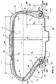
- This tire 1 is reinforced by a carcass reinforcement 5 composed of a first ply 51, axially inside, continuous from one bead to the other and anchored in each bead to a braid-like rod 30, 30 'for to form reversals 510 and 510 '.
- This first ply 51 is formed of a rubber matrix reinforced by cables of aliphatic polyamide, arranged in a direction making with the circumferential direction an angle close to 90 °, said angle being measured in the equatorial plane of the tire.
- a second axially outer carcass ply 52 completes the armature 5, and is formed of the same elements as those constituting the main ply 51; the ply 52 has two lower ends 520, 520 'pressed against the turns 510, 510' of the ply 51 and situated radially below a straight line parallel to the axis of rotation and tangential radially outwardly to the contour of the plies. rods 30 and 30 '.
- This crown reinforcement 6 Radially outside the carcass reinforcement 5, is disposed a crown reinforcement 6, itself surmounted by a tread 7.
- This crown reinforcement 6 comprises two plies 61 and 62, called working plies, each working ply comprising a plurality of metal ropes forming an angle of between 15 ° and 25 ° with the circumferential direction, the ropes of a ply 61 being crossed with the ropes of the other ply 62.
- the working plies 61 and 62 are radially surmounted by a ply 63 of greater width than the widths of the plies 61, 62 and obtained by winding an aromatic polyamide cable, which confers to this cable an approximately circumferential direction on the tire.
- the outer sidewall 4 intended to be located towards the outside of the vehicle on which the tire 1 is mounted, comprises an additional inextensible reinforcement ring 8 positioned in the sidewall so that the center of gravity G8 of its meridian section is radially located. at a distance H1 from the base of the bead equal to 59% of the height H of the tire (measured on the tire mounted on the rim and inflated to the recommended pressure relative to the bead base which is also a rim base).
- the inner side 4 'intended to be located towards the inside of the vehicle comprises an additional reinforcing ring 8' inextensible positioned in the side so that the center of gravity G8 'of its meridian section is radially located at a distance H2 from the base of the bead equal to 48% of the height H of the tire.
- inextensible ring is meant a ring which, under a circumferential tension force equal to 10% of its breaking force has a relative elongation of at most 1%.
- the base of a bead is conventionally the straight line parallel to the axis of rotation of the tire and passing through the point of intersection of the trace of the vertical wall axially outside each bead with the generator of the bead seat.
- each additional ring 8, 8 ' radially separates each flank into a radially upper portion and a radially lower portion; the radially upper portion of small radial height is the radially outward portion of the additional rings 8, 8 'where the carcass plies 51, 52 are substantially superimposed, which corresponds to what is usually called a "pneumatic" part flank.
- the radially lower part is the part radially inside the additional rings 8, 8 'where the carcass plies 51 and 52 are axially separated by a rubber compound profile, respectively 80, 80', of great thickness, and of hardness Shore A high, since it is equal to 80, and which corresponds to what is usually called a structural part.
- Shore A hardness is measured according to ASTM D2240.
- An additional reinforcement frame 53 completes the structure of the extending bead. the first flank 4.
- This additional reinforcement 53 is composed of a ply of textile elements making with the circumferential direction an angle of between 0 ° and 45 °, said ply being arranged axially between the first and second plies 51, 52 of carcass reinforcement and against the axially outer carcass ply 52.
- each profile 80, 80 ' maximum substantially in the middle, is equal in the case described to substantially 6% of the height H.
- Said second radially lower portion is strongly inclined relative to the axial direction.
- flank ring 8 in particular inwardly (i.e. in the direction of the ring 8 ').
- the essentially pneumatic structure of the upper part of each flank has the faculty of facilitating the flattening of the tread on the ground and thus increasing the width of contact area between said tire and the ground, while maintaining pneumatic audit of standardized dimensions.
- the increase in the volume of tread rubber that works has many advantages and in particular an improvement in all the performance related to the contact between the tire and the ground: adhesion, wear, heating, behavior, to mention only the performances the most heavily influenced.
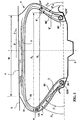
- the tire 1 is shown inflated and crushed in a turn configuration on a ground S, the arrow marked F in the drawing indicating the direction of the transverse forces exerted by the ground on the contact surface of the tread 7.
- the position shown corresponds to the tire on the front left of a vehicle turning to the right.
- the diameters of the beads are substantially identical and allow the mounting of the tire on a rim whose bead seats have identical diameters; however, it may be advantageous to combine the features of the invention with the fact that the bead of the tire prolonging the first side intended to be placed on the outside of the vehicle has a diameter smaller than the diameter of the other bead.
- at least one rim seat may have a generator whose axially innermost points are on a circle of diameter greater than the diameter of the circle on which are located the points of the same generatrix axially the most. outside.
- additional reinforcing reinforcements are added in the flanks of the tire in question, for example a sheet of reinforcement elements wound around at least one additional flank ring to form two flanges. strands radially above said ring, axially adjacent strands which may advantageously replace at least one of the rubber profiles 80, 80 '.
Landscapes
- Engineering & Computer Science (AREA)
- Mechanical Engineering (AREA)
- Tires In General (AREA)
- Rigid Pipes And Flexible Pipes (AREA)
Claims (10)
- Luftreifen (1), der zwei Wülste (3, 3'), einen Scheitel, der mit einem Laufstreifen (7) versehen ist, und eine erste und zweite Flanke (4, 4') aufweist, die den Scheitel mit den Wülsten verbinden, wobei die Wülste radial an der Innenseite Bereiche aufweisen, die einen axial und radial nach außen offenen Winkel bilden und mit einer Felge in Kontakt kommen sollen, die Felgensitze aufweist, die in einem ebenfalls axial und radial nach außen offenen Winkel (γ) geneigt sind, wobei der Luftreifen mit einer Karkassenbewehrung (5) verstärkt ist, die mindestens eine Karkassenlage umfasst, die aus Verstärkungen gebildet wird, die in der Lage zueinander parallel verlaufen und mit der Umfangsrichtung einen Winkel (α) von 60 ° ≤ α ≤ 90 ° bilden,
wobei die Bewehrung in jedem Wulst an mindestens einem ringförmigen Verankerungselement (30, 30') verankert ist und sich radial über der Karkassenbewehrung eine Scheitelbewehrung (6) befindet, über der der Laufstreifen (7) angeordnet ist,
wobei die erste und zweite Flanke (4, 4') jeweils einen zusätzlichen nichtdehnbaren Ring (8, 8') aufweist,
wobei die Gerade, die durch den Schwerpunkt (G8) des Querschnitts des Rings (8) der ersten Flanke (4) und durch den Ring zur Verankerung (30) des Wulstes verläuft, der sich in der Verlängerung der ersten Flanke befindet, mit der Drehachse einen nach außen offenen Winkel (β1) bildet,
wobei die Gerade, die durch den Schwerpunkt (G8') des Querschnitts des Rings der zweiten Flanke (4') und den Ring zur Verankerung (30') des Wulstes verläuft, der sich in der Verlängerung der zweiten Flanke befindet, mit der Drehachse einen nach außen offenen Winkel (β2) bildet,
wobei der auf der Felge montierte, auf den empfohlenen Druck aufgepumpte Luftreifen im Meridianschnitt dadurch gekennzeichnet ist, dass:- sich der zusätzliche nichtdehnbare Ring (8, 8') der ersten und zweiten Flanke (4, 4') axial an der Innenseite der axial am weitesten außen liegenden Karkassenlage befindet,- jede Flanke (4, 4') ein Verbindungsprofilteil (80, 80') aufweist, das in radialer Richtung zwischen dem zusätzlichen Ring und dem ringförmigen Verankerungselement des Wulstes liegt,und dadurch, dass
sich der Winkel (β1) von dem Winkel (β2) unterscheidet. - Luftreifen nach Anspruch 1, dadurch gekennzeichnet, dass die erste Flanke (4) an der Außenseite eines mit dem Luftreifen ausgestatteten Kraftfahrzeugs angebracht werden soll.
- Luftreifen nach Anspruch 1 oder nach Anspruch 2, dadurch gekennzeichnet, dass der an der ersten Flanke (4) gemessene Winkel (β1) kleiner ist als der an der zweiten Flanke (4') gemessene Winkel (β2).
- Luftreifen nach Anspruch 3, dadurch gekennzeichnet, dass der an der ersten Flanke (4) gemessene Winkel (β1) höchstens 70° beträgt und der an der zweiten Flanke (4') gemessene Winkel (β2) größer 70° ist.
- Luftreifen nach Anspruch 4, dadurch gekennzeichnet, dass der an der zweiten Flanke (4') gemessene Winkel (β2) im Bereich von 75 bis 100 ° liegt.
- Luftreifen nach einem der Ansprüche 1 bis 5, dadurch gekennzeichnet, dass sich der zusätzliche Ring (8) der ersten Flanke (4) in radialer Richtung in einem Abstand (H1) von der Wulstbasis befindet und der zusätzliche Ring der zweiten Flanke (4') radial in einem Abstand (H2) von der Wulstbasis liegt, wobei die Abstände (H1) und (H2) kleiner sind als zwei Drittel der Höhe (H) des Luftreifens auf seiner Montagefelge, wobei die Höhe (H) zwischen der Basis des Wulstes und dem Punkt des Scheitels auf der Äquatorialebene des Luftreifens gemessen wird.
- Luftreifen nach Anspruch 6, dadurch gekennzeichnet, dass die Höhe (H1) größer ist als die Höhe (H2).
- Luftreifen nach Anspruch 7, dadurch gekennzeichnet, dass (H1) größer ist als ein Drittel der Höhe (H) des Luftreifens auf der Felge.
- Luftreifen nach einem der Ansprüche 1 bis 7, dadurch gekennzeichnet, dass in jeder Flanke das axial an der Innenseite der axial äußeren Karkassenlage liegende Verbindungsprofilteil (80, 80') aus einem Elastomermaterial mit einer Shore A-Härte von mindestens 65 besteht.
- Luftreifen nach einem der Ansprüche 1 bis 8, dadurch gekennzeichnet, dass die Karkassenbewehrung aus mindestens zwei Lagen von zueinander in jeder Lage parallelen Verstärkungselementen gebildet wird, die mit der Umfangsrichtung einen Winkel (α) von 60 ° ≤ α ≤ 90 ° bilden,
wobei mindestens eine Lage in jedem Wulst durch Hochschlag um das Verankerungselement des Wulstes verankert ist, die zweite axial innere Lage axial an der Innenseite des zusätzlichen Rings der Flanke und des Verbindungsprofilteils zwischen dem zusätzlichen Ring und dem Verankerungselement des Rings liegt.
Applications Claiming Priority (3)
| Application Number | Priority Date | Filing Date | Title |
|---|---|---|---|
| FR0109966A FR2827810A1 (fr) | 2001-07-25 | 2001-07-25 | Pneumatique ayant des flancs dissymetriques et renforces |
| FR0109966 | 2001-07-25 | ||
| PCT/EP2002/007953 WO2003010011A1 (fr) | 2001-07-25 | 2002-07-17 | Pneumatique ayant des flancs dissymetriques et renforces |
Publications (2)
| Publication Number | Publication Date |
|---|---|
| EP1414655A1 EP1414655A1 (de) | 2004-05-06 |
| EP1414655B1 true EP1414655B1 (de) | 2006-02-01 |
Family
ID=8865911
Family Applications (1)
| Application Number | Title | Priority Date | Filing Date |
|---|---|---|---|
| EP02751144A Expired - Lifetime EP1414655B1 (de) | 2001-07-25 | 2002-07-17 | Lufreifen mit asymmetrischen und verstärkten seitenwänden |
Country Status (11)
| Country | Link |
|---|---|
| US (1) | US6883568B2 (de) |
| EP (1) | EP1414655B1 (de) |
| JP (1) | JP4302516B2 (de) |
| CN (1) | CN1273315C (de) |
| AT (1) | ATE316869T1 (de) |
| BR (1) | BR0211367B1 (de) |
| CA (1) | CA2454387A1 (de) |
| DE (1) | DE60209012T2 (de) |
| ES (1) | ES2256503T3 (de) |
| FR (1) | FR2827810A1 (de) |
| WO (1) | WO2003010011A1 (de) |
Cited By (2)
| Publication number | Priority date | Publication date | Assignee | Title |
|---|---|---|---|---|
| WO2009013265A1 (fr) * | 2007-07-23 | 2009-01-29 | Société de Technologie Michelin | Procede de fabrication d'un pneumatique asymetrique |
| FR2938191A1 (fr) * | 2008-11-07 | 2010-05-14 | Oreal | Emulsion huile-dans-eau contenant un polymere amphiphile et un elastomere silicone |
Families Citing this family (11)
| Publication number | Priority date | Publication date | Assignee | Title |
|---|---|---|---|---|
| BRPI0407933A (pt) * | 2003-03-03 | 2006-02-21 | Technologie Michelin E Micheli | pneumático |
| JP4568681B2 (ja) * | 2005-12-21 | 2010-10-27 | 株式会社ブリヂストン | 空気入りタイヤ |
| JP5148511B2 (ja) * | 2006-02-01 | 2013-02-20 | コンパニー ゼネラール デ エタブリッスマン ミシュラン | タイヤを製造する方法 |
| JP5257185B2 (ja) * | 2008-05-19 | 2013-08-07 | 横浜ゴム株式会社 | 空気入りタイヤ |
| WO2012114743A1 (ja) * | 2011-02-24 | 2012-08-30 | 株式会社ブリヂストン | 空気入りラジアルタイヤ |
| WO2012120826A1 (ja) * | 2011-03-04 | 2012-09-13 | 株式会社ブリヂストン | 空気入りタイヤ |
| CN104321202B (zh) * | 2012-04-10 | 2018-01-19 | 倍耐力轮胎股份公司 | 用于车辆车轮的轮胎 |
| KR101596343B1 (ko) * | 2014-07-30 | 2016-02-23 | 금호타이어 주식회사 | 공기입 타이어 |
| DE102014226783B4 (de) * | 2014-12-22 | 2020-01-02 | Continental Automotive Gmbh | System und Verfahren zur Ermittlung wenigstens eines, eine Abmessung eines Reifenlatsches an einem Reifen eines Rades eines Fahrzeuges charakterisierenden Reifenlatschparameters |
| KR102723199B1 (ko) * | 2020-06-30 | 2024-10-30 | 꽁빠니 제네날 드 에따블리세망 미쉘린 | 질량 비대칭 타이어 |
| JP7569282B2 (ja) * | 2021-06-30 | 2024-10-17 | 株式会社ブリヂストン | タイヤ |
Family Cites Families (7)
| Publication number | Priority date | Publication date | Assignee | Title |
|---|---|---|---|---|
| GB191403276A (en) * | 1914-02-07 | 1914-09-10 | Carl Victor Johnson | Improvements in Tamper Proof Bottles. |
| US2186178A (en) * | 1937-02-11 | 1940-01-09 | Jacob George Smith | Pneumatic tire |
| US3656532A (en) * | 1969-12-22 | 1972-04-18 | Goodyear Tire & Rubber | Asymmetric tire |
| US4061172A (en) * | 1973-11-14 | 1977-12-06 | The Toyo Rubber Industry Co., Ltd. | Assembly of pneumatic tire and rim |
| JPH09207526A (ja) * | 1995-10-23 | 1997-08-12 | Sumitomo Rubber Ind Ltd | 空気入りタイヤ |
| JP3377448B2 (ja) * | 1998-07-27 | 2003-02-17 | 住友ゴム工業株式会社 | ランフラットタイヤ |
| FR2812240A1 (fr) * | 2000-07-31 | 2002-02-01 | Michelin Soc Tech | Pneumatique avec des flancs de structure amelioree |
-
2001
- 2001-07-25 FR FR0109966A patent/FR2827810A1/fr active Pending
-
2002
- 2002-07-17 WO PCT/EP2002/007953 patent/WO2003010011A1/fr not_active Ceased
- 2002-07-17 JP JP2003515388A patent/JP4302516B2/ja not_active Expired - Fee Related
- 2002-07-17 CA CA002454387A patent/CA2454387A1/fr not_active Abandoned
- 2002-07-17 AT AT02751144T patent/ATE316869T1/de not_active IP Right Cessation
- 2002-07-17 DE DE60209012T patent/DE60209012T2/de not_active Expired - Lifetime
- 2002-07-17 BR BRPI0211367-8A patent/BR0211367B1/pt not_active IP Right Cessation
- 2002-07-17 CN CNB028148738A patent/CN1273315C/zh not_active Expired - Fee Related
- 2002-07-17 ES ES02751144T patent/ES2256503T3/es not_active Expired - Lifetime
- 2002-07-17 EP EP02751144A patent/EP1414655B1/de not_active Expired - Lifetime
-
2004
- 2004-01-26 US US10/763,257 patent/US6883568B2/en not_active Expired - Lifetime
Cited By (3)
| Publication number | Priority date | Publication date | Assignee | Title |
|---|---|---|---|---|
| WO2009013265A1 (fr) * | 2007-07-23 | 2009-01-29 | Société de Technologie Michelin | Procede de fabrication d'un pneumatique asymetrique |
| FR2919220A1 (fr) * | 2007-07-23 | 2009-01-30 | Michelin Soc Tech | Procede de fabrication d'un pneumatique asymetrique. |
| FR2938191A1 (fr) * | 2008-11-07 | 2010-05-14 | Oreal | Emulsion huile-dans-eau contenant un polymere amphiphile et un elastomere silicone |
Also Published As
| Publication number | Publication date |
|---|---|
| BR0211367A (pt) | 2004-09-21 |
| FR2827810A1 (fr) | 2003-01-31 |
| ATE316869T1 (de) | 2006-02-15 |
| JP4302516B2 (ja) | 2009-07-29 |
| ES2256503T3 (es) | 2006-07-16 |
| DE60209012D1 (de) | 2006-04-13 |
| JP2004535327A (ja) | 2004-11-25 |
| US20040226642A1 (en) | 2004-11-18 |
| DE60209012T2 (de) | 2006-09-14 |
| EP1414655A1 (de) | 2004-05-06 |
| CA2454387A1 (fr) | 2003-02-06 |
| CN1273315C (zh) | 2006-09-06 |
| WO2003010011A1 (fr) | 2003-02-06 |
| BR0211367B1 (pt) | 2010-12-14 |
| CN1535215A (zh) | 2004-10-06 |
| US6883568B2 (en) | 2005-04-26 |
Similar Documents
| Publication | Publication Date | Title |
|---|---|---|
| EP1028858B1 (de) | Verstärkungsgürtel für lkw-reifen | |
| EP1237739B1 (de) | Wulst für notlaufreifen | |
| CA2318327C (fr) | Bourrelet de pneumatique avec elements de renfort circonferentiels | |
| EP1077815B1 (de) | Verstärkungsgürtel von radialen reifen | |
| EP1414655A1 (de) | Lufreifen mit asymmetrischen und verstärkten seitenwänden | |
| EP1307349B1 (de) | Radiale luftreifen mit einer die seitenwände verstärkenden struktur | |
| EP2429834B1 (de) | Verstärkungseinlage versehen mit bi-material verstärkungen und reifen mit einer solchen verstärkungseinlage | |
| EP1254034B1 (de) | Reifenwulst mit verlängerter mobilität | |
| FR2804907A1 (fr) | Bourrelet de pneumatique avec nappes textiles | |
| EP1353811B1 (de) | Fahrzeugluftreifen mit einem konzentrisch zum reifen angerordneten ring | |
| WO2002094584A1 (fr) | Pneumatique avec nappe carcasse a bi-ancrage | |
| EP1601539B1 (de) | Reifen mit verstärkter flanke und herstellungsverfahren dafür | |
| EP1789266B1 (de) | Reifen mit erweiterter mobilität, der mehrere sehr niedrige ankerbereiche aufweist | |
| EP2150423B1 (de) | Reifen für fahrzeug mit verstärkungen in den seitenwänden | |
| FR2919220A1 (fr) | Procede de fabrication d'un pneumatique asymetrique. | |
| FR2805491A1 (fr) | Jante avec sieges inclines vers l'exterieur et ensembles comprenant une telle jante et un appui de soutien gonfle | |
| CA2869496A1 (fr) | Armature de carcasse pour pneumatique d'avion | |
| WO2006024561A1 (fr) | Pneumatique a mobilite etendue avec zone d'ancrage a moment d'inertie eleve | |
| EP2219886B1 (de) | Reifen mit verstärkten seitenwänden aufweisendes fahrzeug | |
| EP1883545B1 (de) | Reifen für zweirädrige fahrzeuge | |
| EP4323205A1 (de) | Optimierte architektur eines tiefbaureifens | |
| FR2887817A1 (fr) | Pneumatique pour vehicules lourds | |
| WO2003093032A1 (fr) | Pneumatique avec bourrelet dont la zone d'ancrage est microdeformable | |
| WO2005047027A1 (fr) | Pneumatique a mobilite etendue a double renfort et bourrelets asymetrique |
Legal Events
| Date | Code | Title | Description |
|---|---|---|---|
| PUAI | Public reference made under article 153(3) epc to a published international application that has entered the european phase |
Free format text: ORIGINAL CODE: 0009012 |
|
| 17P | Request for examination filed |
Effective date: 20040225 |
|
| AK | Designated contracting states |
Kind code of ref document: A1 Designated state(s): AT BE BG CH CY CZ DE DK EE ES FI FR GB GR IE IT LI LU MC NL PT SE SK TR |
|
| AX | Request for extension of the european patent |
Extension state: AL LT LV MK RO SI |
|
| 17Q | First examination report despatched |
Effective date: 20040819 |
|
| GRAP | Despatch of communication of intention to grant a patent |
Free format text: ORIGINAL CODE: EPIDOSNIGR1 |
|
| GRAS | Grant fee paid |
Free format text: ORIGINAL CODE: EPIDOSNIGR3 |
|
| GRAA | (expected) grant |
Free format text: ORIGINAL CODE: 0009210 |
|
| AK | Designated contracting states |
Kind code of ref document: B1 Designated state(s): AT BE BG CH CY CZ DE DK EE ES FI FR GB GR IE IT LI LU MC NL PT SE SK TR |
|
| PG25 | Lapsed in a contracting state [announced via postgrant information from national office to epo] |
Ref country code: FI Free format text: LAPSE BECAUSE OF FAILURE TO SUBMIT A TRANSLATION OF THE DESCRIPTION OR TO PAY THE FEE WITHIN THE PRESCRIBED TIME-LIMIT Effective date: 20060201 Ref country code: IE Free format text: LAPSE BECAUSE OF FAILURE TO SUBMIT A TRANSLATION OF THE DESCRIPTION OR TO PAY THE FEE WITHIN THE PRESCRIBED TIME-LIMIT Effective date: 20060201 Ref country code: NL Free format text: LAPSE BECAUSE OF FAILURE TO SUBMIT A TRANSLATION OF THE DESCRIPTION OR TO PAY THE FEE WITHIN THE PRESCRIBED TIME-LIMIT Effective date: 20060201 Ref country code: SK Free format text: LAPSE BECAUSE OF FAILURE TO SUBMIT A TRANSLATION OF THE DESCRIPTION OR TO PAY THE FEE WITHIN THE PRESCRIBED TIME-LIMIT Effective date: 20060201 Ref country code: AT Free format text: LAPSE BECAUSE OF FAILURE TO SUBMIT A TRANSLATION OF THE DESCRIPTION OR TO PAY THE FEE WITHIN THE PRESCRIBED TIME-LIMIT Effective date: 20060201 |
|
| REG | Reference to a national code |
Ref country code: GB Ref legal event code: FG4D Free format text: NOT ENGLISH |
|
| REG | Reference to a national code |
Ref country code: CH Ref legal event code: EP |
|
| REG | Reference to a national code |
Ref country code: IE Ref legal event code: FG4D Free format text: LANGUAGE OF EP DOCUMENT: FRENCH |
|
| REF | Corresponds to: |
Ref document number: 60209012 Country of ref document: DE Date of ref document: 20060413 Kind code of ref document: P |
|
| PG25 | Lapsed in a contracting state [announced via postgrant information from national office to epo] |
Ref country code: DK Free format text: LAPSE BECAUSE OF FAILURE TO SUBMIT A TRANSLATION OF THE DESCRIPTION OR TO PAY THE FEE WITHIN THE PRESCRIBED TIME-LIMIT Effective date: 20060501 Ref country code: SE Free format text: LAPSE BECAUSE OF FAILURE TO SUBMIT A TRANSLATION OF THE DESCRIPTION OR TO PAY THE FEE WITHIN THE PRESCRIBED TIME-LIMIT Effective date: 20060501 Ref country code: BG Free format text: LAPSE BECAUSE OF FAILURE TO SUBMIT A TRANSLATION OF THE DESCRIPTION OR TO PAY THE FEE WITHIN THE PRESCRIBED TIME-LIMIT Effective date: 20060501 |
|
| GBT | Gb: translation of ep patent filed (gb section 77(6)(a)/1977) |
Effective date: 20060427 |
|
| NLV1 | Nl: lapsed or annulled due to failure to fulfill the requirements of art. 29p and 29m of the patents act | ||
| PG25 | Lapsed in a contracting state [announced via postgrant information from national office to epo] |
Ref country code: PT Free format text: LAPSE BECAUSE OF FAILURE TO SUBMIT A TRANSLATION OF THE DESCRIPTION OR TO PAY THE FEE WITHIN THE PRESCRIBED TIME-LIMIT Effective date: 20060703 |
|
| REG | Reference to a national code |
Ref country code: ES Ref legal event code: FG2A Ref document number: 2256503 Country of ref document: ES Kind code of ref document: T3 |
|
| PG25 | Lapsed in a contracting state [announced via postgrant information from national office to epo] |
Ref country code: MC Free format text: LAPSE BECAUSE OF NON-PAYMENT OF DUE FEES Effective date: 20060731 Ref country code: BE Free format text: LAPSE BECAUSE OF NON-PAYMENT OF DUE FEES Effective date: 20060731 Ref country code: LI Free format text: LAPSE BECAUSE OF NON-PAYMENT OF DUE FEES Effective date: 20060731 Ref country code: CH Free format text: LAPSE BECAUSE OF NON-PAYMENT OF DUE FEES Effective date: 20060731 |
|
| REG | Reference to a national code |
Ref country code: IE Ref legal event code: FD4D |
|
| PLBE | No opposition filed within time limit |
Free format text: ORIGINAL CODE: 0009261 |
|
| STAA | Information on the status of an ep patent application or granted ep patent |
Free format text: STATUS: NO OPPOSITION FILED WITHIN TIME LIMIT |
|
| 26N | No opposition filed |
Effective date: 20061103 |
|
| REG | Reference to a national code |
Ref country code: CH Ref legal event code: PL |
|
| BERE | Be: lapsed |
Owner name: SOC. DE TECHNOLOGIE MICHELIN Effective date: 20060731 Owner name: MICHELIN RECHERCHE ET TECHNIQUE S.A. Effective date: 20060731 |
|
| PG25 | Lapsed in a contracting state [announced via postgrant information from national office to epo] |
Ref country code: CZ Free format text: LAPSE BECAUSE OF FAILURE TO SUBMIT A TRANSLATION OF THE DESCRIPTION OR TO PAY THE FEE WITHIN THE PRESCRIBED TIME-LIMIT Effective date: 20060201 Ref country code: GR Free format text: LAPSE BECAUSE OF FAILURE TO SUBMIT A TRANSLATION OF THE DESCRIPTION OR TO PAY THE FEE WITHIN THE PRESCRIBED TIME-LIMIT Effective date: 20060502 |
|
| PG25 | Lapsed in a contracting state [announced via postgrant information from national office to epo] |
Ref country code: EE Free format text: LAPSE BECAUSE OF FAILURE TO SUBMIT A TRANSLATION OF THE DESCRIPTION OR TO PAY THE FEE WITHIN THE PRESCRIBED TIME-LIMIT Effective date: 20060201 |
|
| PG25 | Lapsed in a contracting state [announced via postgrant information from national office to epo] |
Ref country code: TR Free format text: LAPSE BECAUSE OF FAILURE TO SUBMIT A TRANSLATION OF THE DESCRIPTION OR TO PAY THE FEE WITHIN THE PRESCRIBED TIME-LIMIT Effective date: 20060201 Ref country code: LU Free format text: LAPSE BECAUSE OF NON-PAYMENT OF DUE FEES Effective date: 20060717 |
|
| PGFP | Annual fee paid to national office [announced via postgrant information from national office to epo] |
Ref country code: ES Payment date: 20080729 Year of fee payment: 7 |
|
| PG25 | Lapsed in a contracting state [announced via postgrant information from national office to epo] |
Ref country code: CY Free format text: LAPSE BECAUSE OF FAILURE TO SUBMIT A TRANSLATION OF THE DESCRIPTION OR TO PAY THE FEE WITHIN THE PRESCRIBED TIME-LIMIT Effective date: 20060201 |
|
| PGFP | Annual fee paid to national office [announced via postgrant information from national office to epo] |
Ref country code: GB Payment date: 20080722 Year of fee payment: 7 |
|
| GBPC | Gb: european patent ceased through non-payment of renewal fee |
Effective date: 20090717 |
|
| PG25 | Lapsed in a contracting state [announced via postgrant information from national office to epo] |
Ref country code: GB Free format text: LAPSE BECAUSE OF NON-PAYMENT OF DUE FEES Effective date: 20090717 |
|
| REG | Reference to a national code |
Ref country code: ES Ref legal event code: FD2A Effective date: 20090718 |
|
| PG25 | Lapsed in a contracting state [announced via postgrant information from national office to epo] |
Ref country code: ES Free format text: LAPSE BECAUSE OF NON-PAYMENT OF DUE FEES Effective date: 20090718 |
|
| PGFP | Annual fee paid to national office [announced via postgrant information from national office to epo] |
Ref country code: IT Payment date: 20120723 Year of fee payment: 11 |
|
| PG25 | Lapsed in a contracting state [announced via postgrant information from national office to epo] |
Ref country code: IT Free format text: LAPSE BECAUSE OF NON-PAYMENT OF DUE FEES Effective date: 20130717 |
|
| REG | Reference to a national code |
Ref country code: FR Ref legal event code: PLFP Year of fee payment: 15 |
|
| REG | Reference to a national code |
Ref country code: FR Ref legal event code: PLFP Year of fee payment: 16 |
|
| REG | Reference to a national code |
Ref country code: FR Ref legal event code: PLFP Year of fee payment: 17 |
|
| PGFP | Annual fee paid to national office [announced via postgrant information from national office to epo] |
Ref country code: FR Payment date: 20180725 Year of fee payment: 17 Ref country code: DE Payment date: 20180723 Year of fee payment: 17 |
|
| REG | Reference to a national code |
Ref country code: DE Ref legal event code: R119 Ref document number: 60209012 Country of ref document: DE |
|
| PG25 | Lapsed in a contracting state [announced via postgrant information from national office to epo] |
Ref country code: DE Free format text: LAPSE BECAUSE OF NON-PAYMENT OF DUE FEES Effective date: 20200201 |
|
| PG25 | Lapsed in a contracting state [announced via postgrant information from national office to epo] |
Ref country code: FR Free format text: LAPSE BECAUSE OF NON-PAYMENT OF DUE FEES Effective date: 20190731 |