EP1415524A1 - Fadenschneider - Google Patents
Fadenschneider Download PDFInfo
- Publication number
- EP1415524A1 EP1415524A1 EP20030256604 EP03256604A EP1415524A1 EP 1415524 A1 EP1415524 A1 EP 1415524A1 EP 20030256604 EP20030256604 EP 20030256604 EP 03256604 A EP03256604 A EP 03256604A EP 1415524 A1 EP1415524 A1 EP 1415524A1
- Authority
- EP
- European Patent Office
- Prior art keywords
- cutting head
- trimmer
- cutter means
- shaft
- cutter
- Prior art date
- Legal status (The legal status is an assumption and is not a legal conclusion. Google has not performed a legal analysis and makes no representation as to the accuracy of the status listed.)
- Granted
Links
- 238000007688 edging Methods 0.000 description 23
- 238000009966 trimming Methods 0.000 description 20
- 244000025254 Cannabis sativa Species 0.000 description 6
- 239000004743 Polypropylene Substances 0.000 description 4
- 230000008878 coupling Effects 0.000 description 4
- 238000010168 coupling process Methods 0.000 description 4
- 238000005859 coupling reaction Methods 0.000 description 4
- 239000000463 material Substances 0.000 description 4
- 239000004033 plastic Substances 0.000 description 4
- 229920003023 plastic Polymers 0.000 description 4
- -1 polypropylene Polymers 0.000 description 4
- 229920001155 polypropylene Polymers 0.000 description 4
- 241001494496 Leersia Species 0.000 description 1
- 238000006243 chemical reaction Methods 0.000 description 1
- 230000004048 modification Effects 0.000 description 1
- 238000012986 modification Methods 0.000 description 1
Images


Classifications
-
- A—HUMAN NECESSITIES
- A01—AGRICULTURE; FORESTRY; ANIMAL HUSBANDRY; HUNTING; TRAPPING; FISHING
- A01D—HARVESTING; MOWING
- A01D34/00—Mowers; Mowing apparatus of harvesters
- A01D34/01—Mowers; Mowing apparatus of harvesters characterised by features relating to the type of cutting apparatus
- A01D34/412—Mowers; Mowing apparatus of harvesters characterised by features relating to the type of cutting apparatus having rotating cutters
- A01D34/416—Flexible line cutters
-
- A—HUMAN NECESSITIES
- A01—AGRICULTURE; FORESTRY; ANIMAL HUSBANDRY; HUNTING; TRAPPING; FISHING
- A01G—HORTICULTURE; CULTIVATION OF VEGETABLES, FLOWERS, RICE, FRUIT, VINES, HOPS OR SEAWEED; FORESTRY; WATERING
- A01G3/00—Cutting implements specially adapted for horticultural purposes; Delimbing standing trees
- A01G3/06—Hand-held edge trimmers or shears for lawns
- A01G3/062—Motor-driven edge trimmers
-
- A—HUMAN NECESSITIES
- A01—AGRICULTURE; FORESTRY; ANIMAL HUSBANDRY; HUNTING; TRAPPING; FISHING
- A01D—HARVESTING; MOWING
- A01D2101/00—Lawn-mowers
-
- A—HUMAN NECESSITIES
- A01—AGRICULTURE; FORESTRY; ANIMAL HUSBANDRY; HUNTING; TRAPPING; FISHING
- A01D—HARVESTING; MOWING
- A01D34/00—Mowers; Mowing apparatus of harvesters
- A01D34/835—Mowers; Mowing apparatus of harvesters specially adapted for particular purposes
- A01D34/84—Mowers; Mowing apparatus of harvesters specially adapted for particular purposes for edges of lawns or fields, e.g. for mowing close to trees or walls
Definitions
- This invention relates to a grass trimming device which is capable of being switched between at least two alternative configurations which are suitable for grass trimming and edge trimming respectively.
- a known grass trimming device comprises a cutting head mounted at one end of a shaft, an operator handle being positioned at the other end of the shaft.
- the cutting head includes a cutter constituted by a rotatable blade or a rotatable flexible cutting line. The cutting head can be moved relative to the shaft, to position the cutter generally horizontal for grass trimming and generally vertical for edge trimming.
- DE-A-3 010 092 describes a known trimmer of this type, the trimmer having a handle that can be moved from a first socket on the cutting head to a second socket on the same head, in order to shift the cutting head from a configuration in which the cutter plane is horizontal for grass trimming to a configuration in which the cutter is vertical for edge trimming.
- a shaft fitted to the handle is directed upwardly towards the operator. This device suffers from the drawback that changing from one function to the other is difficult, because it is necessary to release and then remove the handle from one socket, and then replace it and lock it into position in the second socket.
- EP-A-0 005 540 shows a similar device where the handle is pivotally adjustable in a plane which is perpendicular to the cutting plane. Changing the configuration of this device requires releasing a handle catch, turning the handle through 180°, releasing the cutting head, and then adjusting it to the required angle. Moreover, a relatively complex arrangement of parts is necessary to achieve the changeover. This results in considerable expense, and a risk that the components, which are not totally covered may be damaged by the ingress of dirt and debris.
- EP-A-0 296 789 describes a trimmer in which the shaft includes a coupling section to which the cutting head is pivotally attached.
- the cutting head includes a surface defining a parting plane at which plane the coupling section is coupled to the cutting head.
- the parting plane extends laterally with respect to the shaft, so that relative movement at the parting plane between the coupling section and the cutting head is about an axis which is perpendicular to the parting plane and obliquely to the shaft, so that relative movement between the coupling section and the cutting head about the parting plane positions the cutter in grass trimming and edge trimming configurations.
- each of the trimmers described above is relatively easy to operate when in the trimming configuration.
- the user when in the edging configuration, the user must stand at right-angles to the edge of a lawn being trimmed, and move sideways along that edge as trimming progresses. This is disadvantageous, in that it is difficult to align the cutter accurately with the edge of the lawn (owing to the eye of the user not being in alignment with the lawn edge), and this can lead to a poor edging performance.
- each of the known trimmers requires a relatively complex series of operations to convert between trimming and edging configurations.
- the aim of the invention is to provide a trimmer having improved edging capabilities.
- the present invention provides a trimmer comprising a cutting head housing a cutter means, and an elongate shaft for supporting the cutting head, the cutting head being connected to the shaft by connection means permitting the cutting head to be positioned with its cutter means either substantially horizontal or substantially vertical without disconnecting the cutting head and the shaft, the shaft having a hand-grippable portion at a position remote from the cutting head, the arrangement being such that the line joining a point within the hand-grippable portion and the connection means is substantially parallel to plane of rotation of the cutter means when the cutter means is substantially vertical.
- connection means is such that the cutting head is movable between positions in which its cutter means is substantially horizontal and substantially vertical in a single movement.
- connection means is such that the cutter means is movable between the substantially horizontal position and the substantially vertical position by an effective rotation of the cutting head relative to the handle of 120° in one direction or 240° in the other direction.
- the connection means is constituted by a rotatable joint.
- the rotatable joint is such that the cutting head is movable between positions in which its cutter means is substantially horizontal and substantially vertical about a single axis.
- the axis of rotation of the rotatable joint lies substantially at 35.5° to the plane of rotation of the cutter means, and lies substantially at 35.5° to the horizontal when the cutting head is positioned with the cutter means either substantially horizontal or substantially vertical.
- connection means of this nature enables the cutting head to be moved between a trimming mode (in which the cutter means is substantially horizontal) and an edging mode (in which the cutter means is substantially vertical) by a simple rotation of the cutting head relative to the shaft.
- a particular advantage of this connection means is that the elongate shaft is generally aligned with a lawn edge in the edging mode, so that the user can carry out an edging operation when positioned behind the cutting head and moving forwards (or backwards) along the edge portion of the lawn.
- the rotatable joint is constituted by a ball-and-socket joint.
- the ball is fixed to the cutting head, and the socket is defined by a generally spherical socket portion formed at the end of the shaft remote from the hand-grippable portion.
- the trimmer may further comprise a motor for driving the cutter means.
- the cutter means is rotatable, and the drive engagement between the motor and the cutter means is a rotatable drive engagement.
- the motor is housed within the ball, and is an electric motor.
- a rotatable cutter line constitutes the cutter means.
- the trimmer further comprises a wheel rotatably mounted on the cutting head.
- the axis of rotation of the wheel may be substantially coincident with the axis of rotation of the cutter means.
- the radius of the wheel is of the order of, but slightly less than, the effective radius of the cutter means.
- the invention also provides a cutting head housing a cutter means, and a shaft for supporting the cutting head, the cutting head being adjustably mounted with respect to the shaft by connection means enabling the cutter means to be moved between substantially vertical and substantially horizontal positions by adjusting the position of the cutting head relative to the shaft by an effective rotation of 120° in one direction or 240° in the other direction.
- the invention further provides a cutting head housing a cutter means, and a shaft for supporting the cutting head, the cutting head being rotatably mounted with respect to the shaft by means of a rotatable joint whose axis of rotation lies substantially at 45° to the plane rotation of the cutter means, and lies substantially at 45° to the horizontal when the cutting head is positioned with its cutter means either substantially horizontal or substantially vertical.
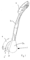
- the trimmer comprises a cutting head 1 which is connected to a shaft 2 by means of a ball-and-socket joint 3.
- the joint 3 is constituted by a housing 3a, which is integrally formed with the shaft 2, and a ball 3b which is fixed to the cutting head 1.
- the housing 3a defines a generally spherical socket which complements the shape of the ball 3b.
- the shaft 2 and the housing 3a are made of a plastics material such as ABS or polypropylene, and the ball 3b is made of a plastics material such as ABS or polypropylene.
- the cutting head 1 includes a rotatable hub 4 which houses a coiled up flexible cutter line (only the free end of portion 5 of which can be seen in the drawings).
- the cutter line 5 exits the hub 4 via an aperture 4a, and can be fed out (in known manner) as the cutter line wears.
- the axis A of rotation of the joint 3 (see Figure 4) lies at an angle of substantially 35.5° to the plane of rotation of the cutter line 5.
- the cutting head 1 is also provided with a guard 6 made of a plastics material such as ABS or polypropylene.
- the guard 6 partially surrounds the hub 4 and the cutter line 5 in such a manner that the cutter line has an effective cutting range which extends somewhat less than 180°.
- the hub 4 is rotatably driven by an electric motor (only the output shaft 7 of which can be seen), the motor being housed within the ball 3b.
- a wheel 8 made of a plastics material such as ABS or polypropylene is mounted between the guard 6 and the housing 3a, the wheel being rotatable relative to the guard about the axis of the motor shaft 7, and having a radius that is slightly less than the effective radius of the cutter line 5.
- a hand grip 9 is provided at the free (upper) end of the shaft 2.
- Figures 2 and 3 show the trimmer 1 in the edging position, that is to say with the cutting head 1 positioned so that the cutter line 5 is generally vertical.
- the rim of the wheel 8 can be positioned on a lawn adjacent to the edge thereof, so that the cutter line 5 is positioned for an edging operation.
- the trimmer can then be advanced along the edge of the lawn to carry out the edging operation.
- the distance between the effective radius of the cutter line 5 and the radius of the wheel 8 defines the depth of cut (cutting swathe) which can be effected with the trimmer in the edging position.
- arrow B indicates the edging direction (that is to say the direction in which the trimmer is moved during edging)
- arrow C indicates the cutting direction (that is to say the direction of rotation of the cutter line 5)
- double-headed arrow D indicates the depth of cut (the cutting swathe) of the cutter line 5.
- Figures 4 and 5 show the trimmer with the cutting head 1 in the trimming position, that is to say with the cutter line 5 generally horizontal. In either position, the axis of rotation of the joint 3 lies at an angle of substantially 35.5° to the horizontal.
- One advantage of the 120° or 240° rotational angle necessary to convert between the two modes is that, in the edging mode, the shaft 2 is generally aligned with the edge of the lawn, so that the user can carry out an edging operation when positioned behind the cutting head 1 and moving forwards (or backwards) along the edge of the lawn.
- This enables the user to line up the cutter line 5 with the edge of the lawn, because the user's eye can be positioned substantially in the plane of the lawn edge.
- trimmers in which the user faces the edge of the lawn when the trimmer is in the edging position, and has to move sideways parallel to the lawn edge to carry out an edging operation.
- a further advantage of the trimmer described above is that, with the trimmer in the edging configuration as shown in Figure 2, the direction of rotation of the cutter line 5 is such as to throw cut grass and debris directly away from the user, that is to say at 180° to the user. This is because the user is positioned "behind" the cutting head.
- trimmer/edgers in which the user stands at substantially 90° to the edge of the lawn (and hence to the plane of rotation of the cutter). Accordingly, there is less chance of the user of the trimmer of the present invention being hit by flying debris than with known devices.
- Another advantage of the trimmer described above is that the joint about which the cutting head 1 rotates is low down, thereby reducing the difference in the height of the hand grip 9 when the trimmer is in the edging and trimming modes.
- a further advantage of this trimmer is that the wheel 8 which has a relatively large diameter.
- the trimmer can, therefore, handle uneven lawn surfaces rather better than known wheeled trimmers which typically have a small wheel hanging off the front of the cutting head.
- trimmer is the ease with which it can be converted from the trimming mode to the edging mode and vice versa.
- a simple, single movement (a rotation of the housing 3a relative to the ball 3b) only is needed for such conversions, and this can be accomplished by rotating the housing with one hand whilst holding the shaft 2 or the hand grip 9 with the other hand.
- an additional hand grip could be provided at the front of the shaft 2 adjacent to the top thereof.
Landscapes
- Life Sciences & Earth Sciences (AREA)
- Environmental Sciences (AREA)
- Biodiversity & Conservation Biology (AREA)
- Ecology (AREA)
- Forests & Forestry (AREA)
- Harvester Elements (AREA)
Applications Claiming Priority (2)
| Application Number | Priority Date | Filing Date | Title |
|---|---|---|---|
| GB0225686 | 2002-11-04 | ||
| GB0225686A GB2394880B (en) | 2002-11-04 | 2002-11-04 | Trimmer |
Publications (2)
| Publication Number | Publication Date |
|---|---|
| EP1415524A1 true EP1415524A1 (de) | 2004-05-06 |
| EP1415524B1 EP1415524B1 (de) | 2007-10-31 |
Family
ID=9947174
Family Applications (1)
| Application Number | Title | Priority Date | Filing Date |
|---|---|---|---|
| EP03256604A Expired - Lifetime EP1415524B1 (de) | 2002-11-04 | 2003-10-20 | Fadenschneider |
Country Status (5)
| Country | Link |
|---|---|
| US (1) | US6997268B2 (de) |
| EP (1) | EP1415524B1 (de) |
| CN (1) | CN100341395C (de) |
| DE (2) | DE03256604T1 (de) |
| GB (2) | GB2417406B (de) |
Cited By (2)
| Publication number | Priority date | Publication date | Assignee | Title |
|---|---|---|---|---|
| WO2004107844A1 (en) * | 2003-06-10 | 2004-12-16 | Torque Holdings Limited | A line trimmer lawn mowing attachment |
| DE102012016026B4 (de) * | 2012-08-13 | 2016-03-03 | Auerswald-Wolff S.A.R.L. | Schneidkopf für Motorsensen mit vertikaler Schneidfadenausrichtung |
Families Citing this family (10)
| Publication number | Priority date | Publication date | Assignee | Title |
|---|---|---|---|---|
| GB2394879B (en) * | 2002-11-04 | 2005-11-23 | Electrolux Outdoor Prod Ltd | Trimmer |
| GB2411565B (en) * | 2004-03-03 | 2007-02-21 | Grey Technology Ltd | Trimming apparatus |
| US20080230240A1 (en) * | 2006-10-24 | 2008-09-25 | Edward Patrick Hurley | Front suspension for a yard tool |
| CN201479600U (zh) * | 2009-06-15 | 2010-05-26 | 南京德朔实业有限公司 | 割草机 |
| GB2510819A (en) * | 2013-02-13 | 2014-08-20 | Stanley Roy Adams | One handed light weight grass trimmer |
| CN104969716B (zh) * | 2014-04-01 | 2018-09-07 | 苏州宝时得电动工具有限公司 | 打草机 |
| US20180014461A1 (en) * | 2016-07-15 | 2018-01-18 | Mary Brewer | Miniature Weed Trimming Assembly |
| US10688647B2 (en) | 2017-05-19 | 2020-06-23 | The Toro Company | Lawn and garden tool with boom having adjustable length and detachable boom sections |
| US10555459B1 (en) * | 2019-01-15 | 2020-02-11 | Benny Crockett | Adjustable shield for a string trimmer |
| EP3927142B1 (de) | 2019-02-20 | 2023-06-21 | Husqvarna Ab | Handschneidwerkzeug |
Citations (5)
| Publication number | Priority date | Publication date | Assignee | Title |
|---|---|---|---|---|
| USRE21274E (en) * | 1939-11-21 | Electric cutter and trimmer | ||
| GB747292A (en) * | 1954-03-10 | 1956-04-04 | James Stuart Brasington | Improved combined grass cutting and edge trimming machine |
| EP0005540A1 (de) * | 1978-05-24 | 1979-11-28 | Wolf-Geräte GmbH | Fadenschneider zum Beschneiden von Rasenkanten |
| EP0296789A1 (de) * | 1987-06-24 | 1988-12-28 | Electrolux Northern Limited | Grastrimmervorrichtung |
| EP0976313A2 (de) * | 1992-12-23 | 2000-02-02 | Skil Europe B.V. | Fadenschneider |
Family Cites Families (16)
| Publication number | Priority date | Publication date | Assignee | Title |
|---|---|---|---|---|
| US296789A (en) * | 1884-04-15 | Jteck | ||
| US721274A (en) * | 1902-03-06 | 1903-02-24 | Hiram Archie Bankston | Framing-square. |
| US747292A (en) * | 1903-06-18 | 1903-12-15 | Christopher C Bradley | Thill-coupling. |
| US976313A (en) * | 1910-08-12 | 1910-11-22 | Lewis B Tebeau | Slipper and the like. |
| US2939262A (en) * | 1958-01-14 | 1960-06-07 | Sr John A Orr | Lawn edger |
| US3086596A (en) | 1960-10-17 | 1963-04-23 | Joseph A Allegretti | Lawn trimmer and edger |
| GB1006000A (en) | 1964-01-07 | 1965-09-29 | John Maxwell Marshall | Improvements in or relating to devices for trimming grass at the edges of lawns |
| GB1006535A (en) | 1964-05-20 | 1965-10-06 | John Maxwell Marshall | Improvements in or relating to devices for trimming grass at the edges of lawns |
| US4043101A (en) * | 1974-01-21 | 1977-08-23 | Rockwell International Corporation | Edger-trimmer head indexing mechanism |
| US4364435A (en) * | 1980-12-22 | 1982-12-21 | Emerson Electric Co. | Lawn edger |
| DE8012962U1 (de) * | 1980-05-13 | 1980-08-14 | Max Langenstein, Feld- Und Gartengeraete Gmbh & Co, 7918 Illertissen | Rasenkantenschneider |
| US4914899A (en) | 1985-12-23 | 1990-04-10 | Carmine Benjamin C | Attachment to a lawn trimmer |
| US4981012A (en) | 1988-06-24 | 1991-01-01 | Wedger, Inc. | Apparatus for converting a gas-powered flexible line trimmer for use as a lawn edger |
| US6092608A (en) | 1998-11-04 | 2000-07-25 | Leger; Herbert J. | Garden tiller pulverizing/edger attachment |
| US6260278B1 (en) * | 1999-06-08 | 2001-07-17 | Andy R. Faher | Hand-held lawn and brush trimmer having manual trimmer head adjustment mechanisms |
| US6301866B1 (en) * | 1999-07-14 | 2001-10-16 | Black & Decker Inc. | Vegetation trimming and edging device with adjustable head orientation |
-
2002
- 2002-11-04 GB GB0524403A patent/GB2417406B/en not_active Expired - Lifetime
- 2002-11-04 GB GB0225686A patent/GB2394880B/en not_active Expired - Fee Related
-
2003
- 2003-10-20 DE DE03256604T patent/DE03256604T1/de active Pending
- 2003-10-20 DE DE60317153T patent/DE60317153T2/de not_active Expired - Lifetime
- 2003-10-20 EP EP03256604A patent/EP1415524B1/de not_active Expired - Lifetime
- 2003-11-03 US US10/699,905 patent/US6997268B2/en not_active Expired - Fee Related
- 2003-11-04 CN CNB2003101209124A patent/CN100341395C/zh not_active Expired - Fee Related
Patent Citations (5)
| Publication number | Priority date | Publication date | Assignee | Title |
|---|---|---|---|---|
| USRE21274E (en) * | 1939-11-21 | Electric cutter and trimmer | ||
| GB747292A (en) * | 1954-03-10 | 1956-04-04 | James Stuart Brasington | Improved combined grass cutting and edge trimming machine |
| EP0005540A1 (de) * | 1978-05-24 | 1979-11-28 | Wolf-Geräte GmbH | Fadenschneider zum Beschneiden von Rasenkanten |
| EP0296789A1 (de) * | 1987-06-24 | 1988-12-28 | Electrolux Northern Limited | Grastrimmervorrichtung |
| EP0976313A2 (de) * | 1992-12-23 | 2000-02-02 | Skil Europe B.V. | Fadenschneider |
Cited By (2)
| Publication number | Priority date | Publication date | Assignee | Title |
|---|---|---|---|---|
| WO2004107844A1 (en) * | 2003-06-10 | 2004-12-16 | Torque Holdings Limited | A line trimmer lawn mowing attachment |
| DE102012016026B4 (de) * | 2012-08-13 | 2016-03-03 | Auerswald-Wolff S.A.R.L. | Schneidkopf für Motorsensen mit vertikaler Schneidfadenausrichtung |
Also Published As
| Publication number | Publication date |
|---|---|
| GB0225686D0 (en) | 2002-12-11 |
| CN100341395C (zh) | 2007-10-10 |
| GB2394880B (en) | 2006-02-01 |
| DE03256604T1 (de) | 2005-03-31 |
| EP1415524B1 (de) | 2007-10-31 |
| CN1509593A (zh) | 2004-07-07 |
| GB2417406A (en) | 2006-03-01 |
| DE60317153D1 (de) | 2007-12-13 |
| GB2394880A (en) | 2004-05-12 |
| GB0524403D0 (en) | 2006-01-11 |
| GB2417406B (en) | 2006-05-10 |
| US20040088867A1 (en) | 2004-05-13 |
| DE60317153T2 (de) | 2008-08-14 |
| US6997268B2 (en) | 2006-02-14 |
Similar Documents
| Publication | Publication Date | Title |
|---|---|---|
| US7584542B2 (en) | Trimmer | |
| US4823464A (en) | Grass trimmer | |
| US5060383A (en) | Vegetation cutter | |
| EP3549429B1 (de) | Rasenmäherroboter | |
| US4463544A (en) | Edger | |
| EP1415524B1 (de) | Fadenschneider | |
| US6370854B1 (en) | Guard and dolly for line trimming apparatus | |
| EP3076778B1 (de) | Zweiwege-schneidvorrichtung | |
| US4796415A (en) | Dolly for line trimming apparatus | |
| US6691792B2 (en) | Edger attachment apparatus for a string trimmer device | |
| US9808961B2 (en) | Electric dust free saw | |
| US6263975B1 (en) | Lawn edger including multi-positionable edge-guide | |
| US6688404B2 (en) | Portable handheld edge cutter | |
| US7360350B1 (en) | Weed trimmer carriage | |
| US7934318B2 (en) | Multipurpose hedge trimmer deflector | |
| US6425231B1 (en) | Multifunctional recycling lawn mower | |
| US5309701A (en) | Lawn mower and edger carriage | |
| US3126968A (en) | Lawn edger | |
| US20040148783A1 (en) | Lawn trimmer guard | |
| US20150201559A1 (en) | Power Mower / Weed-Lawn Edger Combo | |
| US5850728A (en) | Wheeled device for hand held brush cutter | |
| US20030230065A1 (en) | Clutch engagable, in-line, lawn trimmer attachment | |
| GB2450504A (en) | Lawn edge trimmer | |
| CN204132040U (zh) | 修边机 | |
| US20190069481A1 (en) | Attachment plate for supporting walk behind trimmers with third wheel |
Legal Events
| Date | Code | Title | Description |
|---|---|---|---|
| PUAI | Public reference made under article 153(3) epc to a published international application that has entered the european phase |
Free format text: ORIGINAL CODE: 0009012 |
|
| AK | Designated contracting states |
Kind code of ref document: A1 Designated state(s): AT BE BG CH CY CZ DE DK EE ES FI FR GB GR HU IE IT LI LU MC NL PT RO SE SI SK TR |
|
| AX | Request for extension of the european patent |
Extension state: AL LT LV MK |
|
| EL | Fr: translation of claims filed | ||
| 17P | Request for examination filed |
Effective date: 20041029 |
|
| RAP1 | Party data changed (applicant data changed or rights of an application transferred) |
Owner name: ELECTROLUX OUTDOOR PRODUCTS LIMITED |
|
| AKX | Designation fees paid |
Designated state(s): DE FR GB |
|
| DET | De: translation of patent claims | ||
| RAP1 | Party data changed (applicant data changed or rights of an application transferred) |
Owner name: HUSQVARNA UK LIMITED |
|
| 17Q | First examination report despatched |
Effective date: 20060706 |
|
| GRAP | Despatch of communication of intention to grant a patent |
Free format text: ORIGINAL CODE: EPIDOSNIGR1 |
|
| RBV | Designated contracting states (corrected) |
Designated state(s): DE FR |
|
| RIN1 | Information on inventor provided before grant (corrected) |
Inventor name: SMITH, IAN ZETTERSTROM |
|
| GRAS | Grant fee paid |
Free format text: ORIGINAL CODE: EPIDOSNIGR3 |
|
| GRAA | (expected) grant |
Free format text: ORIGINAL CODE: 0009210 |
|
| AK | Designated contracting states |
Kind code of ref document: B1 Designated state(s): DE FR |
|
| REF | Corresponds to: |
Ref document number: 60317153 Country of ref document: DE Date of ref document: 20071213 Kind code of ref document: P |
|
| ET | Fr: translation filed | ||
| PLBE | No opposition filed within time limit |
Free format text: ORIGINAL CODE: 0009261 |
|
| STAA | Information on the status of an ep patent application or granted ep patent |
Free format text: STATUS: NO OPPOSITION FILED WITHIN TIME LIMIT |
|
| 26N | No opposition filed |
Effective date: 20080801 |
|
| REG | Reference to a national code |
Ref country code: DE Ref legal event code: R082 Ref document number: 60317153 Country of ref document: DE Representative=s name: ISARPATENT PATENTANWAELTE BEHNISCH, BARTH, CHA, DE |
|
| REG | Reference to a national code |
Ref country code: DE Ref legal event code: R081 Ref document number: 60317153 Country of ref document: DE Owner name: HUSQVARNA AB, SE Free format text: FORMER OWNER: HUSQVARNA UK LTD., NEWTON AYCLIFFE, DURHAM, GB Effective date: 20140903 Ref country code: DE Ref legal event code: R082 Ref document number: 60317153 Country of ref document: DE Representative=s name: ISARPATENT - PATENTANWAELTE- UND RECHTSANWAELT, DE Effective date: 20140903 Ref country code: DE Ref legal event code: R082 Ref document number: 60317153 Country of ref document: DE Representative=s name: ISARPATENT PATENTANWAELTE BEHNISCH, BARTH, CHA, DE Effective date: 20140903 |
|
| REG | Reference to a national code |
Ref country code: FR Ref legal event code: TP Owner name: HUSQVARNA AB, SE Effective date: 20140930 |
|
| REG | Reference to a national code |
Ref country code: FR Ref legal event code: PLFP Year of fee payment: 13 |
|
| REG | Reference to a national code |
Ref country code: FR Ref legal event code: PLFP Year of fee payment: 14 |
|
| REG | Reference to a national code |
Ref country code: FR Ref legal event code: PLFP Year of fee payment: 15 |
|
| REG | Reference to a national code |
Ref country code: FR Ref legal event code: PLFP Year of fee payment: 16 |
|
| PGFP | Annual fee paid to national office [announced via postgrant information from national office to epo] |
Ref country code: FR Payment date: 20180911 Year of fee payment: 16 |
|
| PGFP | Annual fee paid to national office [announced via postgrant information from national office to epo] |
Ref country code: DE Payment date: 20180912 Year of fee payment: 16 |
|
| REG | Reference to a national code |
Ref country code: DE Ref legal event code: R119 Ref document number: 60317153 Country of ref document: DE |
|
| PG25 | Lapsed in a contracting state [announced via postgrant information from national office to epo] |
Ref country code: DE Free format text: LAPSE BECAUSE OF NON-PAYMENT OF DUE FEES Effective date: 20200501 |
|
| PG25 | Lapsed in a contracting state [announced via postgrant information from national office to epo] |
Ref country code: FR Free format text: LAPSE BECAUSE OF NON-PAYMENT OF DUE FEES Effective date: 20191031 |