EP0976313A2 - Fadenschneider - Google Patents
Fadenschneider Download PDFInfo
- Publication number
- EP0976313A2 EP0976313A2 EP99204032A EP99204032A EP0976313A2 EP 0976313 A2 EP0976313 A2 EP 0976313A2 EP 99204032 A EP99204032 A EP 99204032A EP 99204032 A EP99204032 A EP 99204032A EP 0976313 A2 EP0976313 A2 EP 0976313A2
- Authority
- EP
- European Patent Office
- Prior art keywords
- shank
- motor
- housing
- motor shaft
- handle
- Prior art date
- Legal status (The legal status is an assumption and is not a legal conclusion. Google has not performed a legal analysis and makes no representation as to the accuracy of the status listed.)
- Withdrawn
Links
Images


Classifications
-
- A—HUMAN NECESSITIES
- A01—AGRICULTURE; FORESTRY; ANIMAL HUSBANDRY; HUNTING; TRAPPING; FISHING
- A01D—HARVESTING; MOWING
- A01D34/00—Mowers; Mowing apparatus of harvesters
- A01D34/835—Mowers; Mowing apparatus of harvesters specially adapted for particular purposes
- A01D34/84—Mowers; Mowing apparatus of harvesters specially adapted for particular purposes for edges of lawns or fields, e.g. for mowing close to trees or walls
-
- A—HUMAN NECESSITIES
- A01—AGRICULTURE; FORESTRY; ANIMAL HUSBANDRY; HUNTING; TRAPPING; FISHING
- A01D—HARVESTING; MOWING
- A01D34/00—Mowers; Mowing apparatus of harvesters
- A01D34/835—Mowers; Mowing apparatus of harvesters specially adapted for particular purposes
- A01D34/90—Mowers; Mowing apparatus of harvesters specially adapted for particular purposes for carrying by the operator
Definitions
- the invention relates to a device for trimming vegetation, such as grass and the like, comprising a motor housing, a motor mounted therein, said motor having a motor shaft and a reel carried by the shaft for a line, the end part of which is unwound and cut off over a pre-determined length and rotated about the motor shaft in an active plane perpendicular to the motor shaft; and a handle having a handgrip and a shank connected to the motor housing.
- Such devices can be used in two main positions, namely that wherein the end of the line is swung around in a practically horizontal plane and that wherein the end of the line is swung around in a practically vertical plane.
- the handle For easy handling of the device the handle must therefore be adjusted relative to the housing and the support of the device on the ground must likewise be adapted.
- the invention has for its object to improve the adjustment of the handle relative to the housing.
- the device according to the invention is distinguished in that the shank is connected to the motor housing through a universal joint in order to enable an angular positioning relative to the motor shaft and a rotation of the shank about the longitudinal axis thereof.
- housing 1 On the underside of housing 1 a motor shaft 3 protrudes downward, on which motor shaft is arranged a reel 4 for a trimming line 5.
- the trimming line 5 is wound onto the reel and protected in a reel housing 6, which housing is provided with a passage opening 7 for guiding through the active end part of line 5.
- Housing 6 is closed off on the underside by a press-in cover 9 which can support on the ground. By pressing in a cover 9, a determined length of line 5 is released each time and cut to length in order to enable cutting of the grass.
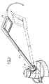
- the housing 1 is further provided with a handle 10 which is embodied with a shank 11 which is connected to a part of the housing 1 via a ball joint 12.
- a second handle 13 can be arranged halfway along the shank.
- the shank and handle 10, 11 can be set in various ways, which is further elucidated below.
- cover plate 15 On the side of housing 1 lying towards the handle 10 the active plane through which the line 5 is moved is protected on the top side by a cover plate 15.
- This cover plate serves as protection against grass, small stones, sand or wire portions being thrown around which can be dangerous for the user and his surroundings.
- the cover plate 15 only covers a sector angle of the complete circle around the bottom end of the housing, so that the wire remains fully visible on the side of the housing 1 remote from the user. This serves for observation of the work.
- the wire end part 5 can come too close to obstacles, as indicated in figure 3a by a wall M.
- the invention proposes arrangement of a bounding element 20.
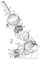
- the bounding element 20 is embodied as a spoke wheel mounted concentrically round the motor shaft 3 on the underside of housing 1.
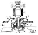
- Figure 2 shows that the spoke wheel can be slightly cup-shaped in order to place the peripheral edge 21 close to the active plane of the wire end 5.
- the bounding wheel 20 is freely rotatable so that, see figure 3a, housing 1 respectively reel housing 6 cannot come too close to the wall M.
- the wire end part 5 is therefore bent through a wider angle whereby wire breakage is avoided.
- the bounding element 20 is used as roller wheel, wherein the periphery 21, whether or not provided with a profile, rolls over the ground surface B. Due to the comparatively large wheel periphery, that is, the relatively large radius of curvature, operation of the device in this position is also considerably facilitated as support.
- the apparatus further comprises a handle 10 which is fixed to the shank 11.
- the shank 11 is accommodated via a universal joint 12 in the line of motor housing 1.
- the universal joint 12 makes it possible to rotate the shank 11 through 180° round the longitudinal axis thereof, for example into the position designated 10' in figure 1.
- the auxiliary handle 13 which is likewise fixed to shank 11 can therein also be rotated through 180° to obtain the correct adjustment for both the hands of the user.
- the universal joint 12 further enables a different angular position of shank 11 relative to housing 1, which is indicated by the positions 11' and 11''.
- shank with handles 10 and 13 can be placed into an optimal position relative to the housing, suitable for adjusting the device as comfortably as possible for the user in the various operational positions according to for instance figures 3a and 3b.
- This universal joint designated as a whole by 12, comprises a spherical chamber 40 connected to motor housing 1 and a spherical body 41 connected to shank 11.
- the periphery of the sphere 41 fits closely in the inside space of spherical chamber 40, which in figure 5 is formed by a spherically recessed portion 42 of the rear wall of housing 1, which is closed off on the top side by a semi-spherical cover 43.
- the latter is fixed by means of a groove 44 into which protrudes an edge of motor housing 1, which cover 43 has a slot-like opening 45 on the side facing the shank 11.
- the shank 11 can not only be placed into a position as according to figure 4 with full lines, but also into a position shown with broken lines, wherein the shank 11 can be adjusted as to angle relative to the motor shaft in motor housing 1 due to the slot-like opening 45 in cover 43.
- the ends of the slot-like openings serve as a stop to bound this rotation.
- the spherical body 41 In order to enable blocking of the height adjustment of the shank, it is recommended to embody the spherical body 41 with a number of straight grooves 46, which extend parallel to the centre line of the sphere perpendicular to the centre line of shank 11, wherein a part of the chamber wall 42 is interrupted, which interruption connects onto a guiding 47 for receiving a locking member 48 provided with straight ribs which co-act with the grooves 46 of the spherical body 41.
- the locking member 48 also see figure 6, is connected round the chamber 42 to a plate-like actuating member 49 which leads to the top of motor housing 1.
- a cap-like foot pedal 50 Arranged on motor housing 1 is a cap-like foot pedal 50 which is supported by protrusions 51 arranged on housing 1 around which pressure springs 52 are arranged.
- the pressure springs provide an upward directed force on the underside of the foot pedal 50.
- the latter is embodied with a ridge-like protrusion 53 which co-act
- the foot pedal 50 By exerting a downward force with the foot on the foot pedal 50, the foot pedal 50 is pressed downward counter to the action of springs 52 and plate-like element 49 is thus likewise pressed downward, which in turn presses the blocking member 48 down into guide 47.
- the ribs thereof come thereby to lie free of the ribs 46 on the spherical body, whereby the spherical body can be rotated relative to the spherical chamber.
- the springs 52 When foot pedal 50 is released the springs 52 will press it upward taking with it the plate 49 and the locking member 48 whereby the ribs 46, and thereby the spherical body 41, are locked in the then adjusted position.
- the spherical shape also enables rotation of shank 11 round its lengthwise axis, whereby the handle 10 can be turned through at least 180 degrees, also see figure 4. This rotation causes a second group of grooves 46' diametrically opposite the first group to come into engagement with the ribs of the locking member 48.
- the cover 43 rotates with the sphere 41 due to two flat surfaces 45' which lie against flat surfaces in cover 43, wherein a ridge 43' defines the end positions which preferably correspond with those as shown in figure 4, that is, that in the one end position handle 10 points downward relative to shank 11 and in the other end position upward, whereby the machine can be used in the operational position of figure 4, that is, the rotation shaft of the motor stands vertically, and in the operational position according to figure 3b wherein the rotation shaft of the motor is oriented horizontally.
- a single elongate handle 35 is used, which is fixed about halfway along the shank 11.
- the handle On the side facing the machine housing the handle has a hammer-shaped end.
- This handle can also be placed into the desired position for use relative to the motor housing by means of the rotatable and pivotable shank 11.
- the advantage of this design is that the user is automatically forced to adjust the correct position, which enhances the work result.
Landscapes
- Life Sciences & Earth Sciences (AREA)
- Environmental Sciences (AREA)
- Harvester Elements (AREA)
Applications Claiming Priority (5)
| Application Number | Priority Date | Filing Date | Title |
|---|---|---|---|
| NL9202252A NL9202252A (nl) | 1992-12-23 | 1992-12-23 | Inrichting voor het trimmen van gewas. |
| NL9202252 | 1992-12-23 | ||
| NL9301416 | 1993-08-16 | ||
| NL9301416A NL9301416A (nl) | 1992-12-23 | 1993-08-16 | Inrichting voor het trimmen van gewas. |
| EP19930203656 EP0603982B1 (de) | 1992-12-23 | 1993-12-23 | Fadenschneider |
Related Parent Applications (1)
| Application Number | Title | Priority Date | Filing Date |
|---|---|---|---|
| EP19930203656 Division EP0603982B1 (de) | 1992-12-23 | 1993-12-23 | Fadenschneider |
Publications (2)
| Publication Number | Publication Date |
|---|---|
| EP0976313A2 true EP0976313A2 (de) | 2000-02-02 |
| EP0976313A3 EP0976313A3 (de) | 2000-03-01 |
Family
ID=26647040
Family Applications (2)
| Application Number | Title | Priority Date | Filing Date |
|---|---|---|---|
| EP19930203656 Expired - Lifetime EP0603982B1 (de) | 1992-12-23 | 1993-12-23 | Fadenschneider |
| EP99204032A Withdrawn EP0976313A3 (de) | 1992-12-23 | 1993-12-23 | Fadenschneider |
Family Applications Before (1)
| Application Number | Title | Priority Date | Filing Date |
|---|---|---|---|
| EP19930203656 Expired - Lifetime EP0603982B1 (de) | 1992-12-23 | 1993-12-23 | Fadenschneider |
Country Status (3)
| Country | Link |
|---|---|
| EP (2) | EP0603982B1 (de) |
| DE (1) | DE69329270T2 (de) |
| NL (1) | NL9301416A (de) |
Cited By (9)
| Publication number | Priority date | Publication date | Assignee | Title |
|---|---|---|---|---|
| FR2845960A1 (fr) * | 2002-10-18 | 2004-04-23 | Stihl Ag & Co Kg Andreas | Outil de travail portatif guide manuellement, comme par exemple une motobeche ou un outil analogue. |
| EP1415524A1 (de) * | 2002-11-04 | 2004-05-06 | Electrolux Outdoor Products | Fadenschneider |
| EP1435194A1 (de) * | 2002-11-04 | 2004-07-07 | Electrolux Outdoor Products Limited | Fadenschneider |
| WO2004107844A1 (en) * | 2003-06-10 | 2004-12-16 | Torque Holdings Limited | A line trimmer lawn mowing attachment |
| WO2005009110A1 (de) * | 2003-07-19 | 2005-02-03 | Wolf-Geräte AG | Fadenschneider |
| EP1746211A1 (de) * | 2005-07-20 | 2007-01-24 | Meint Johannes Bouland | Schutzhaube für Fugenreinigungsmaschine zur Unkrautbekämpfung |
| US9179597B1 (en) * | 2013-04-04 | 2015-11-10 | Adrienne B. Kaspar | Lawnmower with telescoping handle |
| WO2017143994A1 (zh) * | 2016-02-23 | 2017-08-31 | 苏州宝时得电动工具有限公司 | 打草机 |
| WO2020169190A1 (en) * | 2019-02-20 | 2020-08-27 | Husqvarna Ab | Hand-held cutting device |
Families Citing this family (8)
| Publication number | Priority date | Publication date | Assignee | Title |
|---|---|---|---|---|
| DE4430788A1 (de) * | 1994-08-30 | 1996-03-07 | Wolf Geraete Gmbh Vertrieb | Fadenschneider |
| DE4437005C1 (de) * | 1994-10-15 | 1996-01-18 | Bernhardt Dr Med Hildebrandt | Wickelschutzvorrichtung für Motorsensen (Freischneider) mit Fadenschneidkopf |
| DE29603934U1 (de) * | 1996-03-02 | 1996-04-25 | Wolf-Geräte GmbH Vertriebsgesellschaft KG, 57518 Betzdorf | Fadenschneider |
| US5950317A (en) * | 1997-07-23 | 1999-09-14 | Mcculloch Corporation | Wire guard assembly for a string trimmer |
| IT1293659B1 (it) * | 1997-07-31 | 1999-03-08 | Coero Borga Dario | Attrezzo decespugliatore perfezionato per la falciatura manuale di erba e simili |
| GB2387760B (en) * | 2002-04-26 | 2005-06-22 | Electrolux Outdoor Prod Ltd | Trimmer |
| DE102005035024B4 (de) | 2005-07-27 | 2019-04-25 | Andreas Stihl Ag & Co. Kg | Schutzschild für einen Freischneider |
| US10939614B2 (en) | 2017-11-03 | 2021-03-09 | Mtd Products Inc | Trimmer head |
Family Cites Families (12)
| Publication number | Priority date | Publication date | Assignee | Title |
|---|---|---|---|---|
| USRE21274E (en) * | 1939-11-21 | Electric cutter and trimmer | ||
| US2263431A (en) * | 1939-06-08 | 1941-11-18 | Leslie E White | Trimmer |
| US2702978A (en) * | 1949-06-20 | 1955-03-01 | Alvah W Fowler | Lawn mower and edger |
| US3872930A (en) * | 1973-03-13 | 1975-03-25 | Rouel R Campbell | Lawn edger |
| DE2448129A1 (de) * | 1974-10-09 | 1976-04-22 | Gerhard Dr Ing Maerz | Rasenmaeher mit schwenkbarem fuehrungsbuegel |
| EP0005540B1 (de) * | 1978-05-24 | 1982-04-21 | Wolf-Geräte GmbH | Fadenschneider zum Beschneiden von Rasenkanten |
| US4603478A (en) * | 1984-08-13 | 1986-08-05 | Allegretti & Company | Trimmer with adjustable handle |
| DE3506717A1 (de) * | 1985-02-26 | 1986-08-28 | Artur 7266 Neuweiler Mast | Schutzvorrichtung fuer motorsensen |
| ZA858369B (en) * | 1985-10-31 | 1986-07-30 | Middleton J T & Co Pty Ltd | Wheeled line trimmer |
| US5020281A (en) * | 1989-04-03 | 1991-06-04 | American Pneumatic Technologies, Inc. | High speed rotary hand tool with adjustable head coupling |
| US5060383A (en) * | 1990-08-06 | 1991-10-29 | Ratkiewich Richard H | Vegetation cutter |
| US5115870A (en) * | 1990-12-31 | 1992-05-26 | Byrne Steven E | Flexible flail trimmer with combined guide and guard |
-
1993
- 1993-08-16 NL NL9301416A patent/NL9301416A/nl not_active Application Discontinuation
- 1993-12-23 EP EP19930203656 patent/EP0603982B1/de not_active Expired - Lifetime
- 1993-12-23 EP EP99204032A patent/EP0976313A3/de not_active Withdrawn
- 1993-12-23 DE DE1993629270 patent/DE69329270T2/de not_active Expired - Fee Related
Non-Patent Citations (1)
| Title |
|---|
| None |
Cited By (14)
| Publication number | Priority date | Publication date | Assignee | Title |
|---|---|---|---|---|
| FR2845960A1 (fr) * | 2002-10-18 | 2004-04-23 | Stihl Ag & Co Kg Andreas | Outil de travail portatif guide manuellement, comme par exemple une motobeche ou un outil analogue. |
| US7584542B2 (en) | 2002-11-04 | 2009-09-08 | Husqvarna Uk Limited | Trimmer |
| EP1415524A1 (de) * | 2002-11-04 | 2004-05-06 | Electrolux Outdoor Products | Fadenschneider |
| EP1435194A1 (de) * | 2002-11-04 | 2004-07-07 | Electrolux Outdoor Products Limited | Fadenschneider |
| GB2394879B (en) * | 2002-11-04 | 2005-11-23 | Electrolux Outdoor Prod Ltd | Trimmer |
| CN100421544C (zh) * | 2002-11-04 | 2008-10-01 | 赫斯瓦纳英国有限公司 | 修整机 |
| WO2004107844A1 (en) * | 2003-06-10 | 2004-12-16 | Torque Holdings Limited | A line trimmer lawn mowing attachment |
| WO2005009110A1 (de) * | 2003-07-19 | 2005-02-03 | Wolf-Geräte AG | Fadenschneider |
| EP1746211A1 (de) * | 2005-07-20 | 2007-01-24 | Meint Johannes Bouland | Schutzhaube für Fugenreinigungsmaschine zur Unkrautbekämpfung |
| US9179597B1 (en) * | 2013-04-04 | 2015-11-10 | Adrienne B. Kaspar | Lawnmower with telescoping handle |
| WO2017143994A1 (zh) * | 2016-02-23 | 2017-08-31 | 苏州宝时得电动工具有限公司 | 打草机 |
| WO2020169190A1 (en) * | 2019-02-20 | 2020-08-27 | Husqvarna Ab | Hand-held cutting device |
| CN113423264A (zh) * | 2019-02-20 | 2021-09-21 | 胡斯华纳有限公司 | 手持切割装置 |
| CN113423264B (zh) * | 2019-02-20 | 2023-01-17 | 胡斯华纳有限公司 | 手持切割装置 |
Also Published As
| Publication number | Publication date |
|---|---|
| EP0603982B1 (de) | 2000-08-23 |
| EP0976313A3 (de) | 2000-03-01 |
| EP0603982A2 (de) | 1994-06-29 |
| DE69329270T2 (de) | 2001-03-29 |
| DE69329270D1 (de) | 2000-09-28 |
| EP0603982A3 (de) | 1994-10-19 |
| NL9301416A (nl) | 1994-07-18 |
Similar Documents
| Publication | Publication Date | Title |
|---|---|---|
| EP0976313A2 (de) | Fadenschneider | |
| US6769494B2 (en) | Combination line trimmer and edger | |
| EP0653364B1 (de) | Verbesserte Stielzusammensetzung | |
| US6260278B1 (en) | Hand-held lawn and brush trimmer having manual trimmer head adjustment mechanisms | |
| US5661960A (en) | Power tool arm engaging assembly and wheeled platform for a line trimmer | |
| US5560189A (en) | Edging and trimming lawn mower assembly | |
| US4829755A (en) | Trimmer wheels | |
| US4679385A (en) | Attachment for lawn trimmer | |
| EP3549429B1 (de) | Rasenmäherroboter | |
| US4189833A (en) | Apparatus for cutting vegetation | |
| US20260013426A1 (en) | String trimmer head | |
| EP1435194B1 (de) | Fadenschneider | |
| CA1287218C (en) | Device in a grass trimmer | |
| US6971223B2 (en) | Wheeled trimmer device of adjustable height | |
| US6997268B2 (en) | Trimmer | |
| CN1732736B (zh) | 花园工具调节装置 | |
| GB2026928A (en) | Flail-type cutter with adjustable handle and handgrip | |
| AU2020100005A4 (en) | Line trimmer assembly | |
| US7571665B2 (en) | Handle with a power-regulating device | |
| AU2021200001A1 (en) | Line trimmer assembly | |
| US4835874A (en) | Driven marking system for creating a plurality of varied line designs | |
| JP2745450B2 (ja) | スティックエッジヤ | |
| JPS6222128Y2 (de) | ||
| JPH0345540Y2 (de) | ||
| JPS5925135Y2 (ja) | 草刈機のコ−ド刃頭部 |
Legal Events
| Date | Code | Title | Description |
|---|---|---|---|
| PUAI | Public reference made under article 153(3) epc to a published international application that has entered the european phase |
Free format text: ORIGINAL CODE: 0009012 |
|
| PUAL | Search report despatched |
Free format text: ORIGINAL CODE: 0009013 |
|
| AC | Divisional application: reference to earlier application |
Ref document number: 603982 Country of ref document: EP |
|
| AK | Designated contracting states |
Kind code of ref document: A2 Designated state(s): DE FR GB |
|
| AK | Designated contracting states |
Kind code of ref document: A3 Designated state(s): AT BE CH DE DK ES FR GB GR IE IT LI LU MC NL PT SE |
|
| 17P | Request for examination filed |
Effective date: 20000324 |
|
| AKX | Designation fees paid |
Free format text: DE FR GB |
|
| 17Q | First examination report despatched |
Effective date: 20020328 |
|
| STAA | Information on the status of an ep patent application or granted ep patent |
Free format text: STATUS: THE APPLICATION IS DEEMED TO BE WITHDRAWN |
|
| 18D | Application deemed to be withdrawn |
Effective date: 20021008 |