EP1415602A2 - Dispositif d'ostéosynthèse vertébrale pluridirectionelle et modulable, à encombrement réduit - Google Patents
Dispositif d'ostéosynthèse vertébrale pluridirectionelle et modulable, à encombrement réduit Download PDFInfo
- Publication number
- EP1415602A2 EP1415602A2 EP03025168A EP03025168A EP1415602A2 EP 1415602 A2 EP1415602 A2 EP 1415602A2 EP 03025168 A EP03025168 A EP 03025168A EP 03025168 A EP03025168 A EP 03025168A EP 1415602 A2 EP1415602 A2 EP 1415602A2
- Authority
- EP
- European Patent Office
- Prior art keywords
- bone anchoring
- axis
- threaded
- anchoring elements
- bone
- Prior art date
- Legal status (The legal status is an assumption and is not a legal conclusion. Google has not performed a legal analysis and makes no representation as to the accuracy of the status listed.)
- Granted
Links
Images


Classifications
-
- A—HUMAN NECESSITIES
- A61—MEDICAL OR VETERINARY SCIENCE; HYGIENE
- A61B—DIAGNOSIS; SURGERY; IDENTIFICATION
- A61B17/00—Surgical instruments, devices or methods
- A61B17/56—Surgical instruments or methods for treatment of bones or joints; Devices specially adapted therefor
- A61B17/58—Surgical instruments or methods for treatment of bones or joints; Devices specially adapted therefor for osteosynthesis, e.g. bone plates, screws or setting implements
- A61B17/68—Internal fixation devices, including fasteners and spinal fixators, even if a part thereof projects from the skin
- A61B17/70—Spinal positioners or stabilisers, e.g. stabilisers comprising fluid filler in an implant
- A61B17/7049—Connectors, not bearing on the vertebrae, for linking longitudinal elements together
- A61B17/7052—Connectors, not bearing on the vertebrae, for linking longitudinal elements together of variable angle or length
-
- A—HUMAN NECESSITIES
- A61—MEDICAL OR VETERINARY SCIENCE; HYGIENE
- A61B—DIAGNOSIS; SURGERY; IDENTIFICATION
- A61B17/00—Surgical instruments, devices or methods
- A61B17/56—Surgical instruments or methods for treatment of bones or joints; Devices specially adapted therefor
- A61B17/58—Surgical instruments or methods for treatment of bones or joints; Devices specially adapted therefor for osteosynthesis, e.g. bone plates, screws or setting implements
- A61B17/68—Internal fixation devices, including fasteners and spinal fixators, even if a part thereof projects from the skin
- A61B17/70—Spinal positioners or stabilisers, e.g. stabilisers comprising fluid filler in an implant
- A61B17/7001—Screws or hooks combined with longitudinal elements which do not contact vertebrae
- A61B17/7002—Longitudinal elements, e.g. rods
- A61B17/7004—Longitudinal elements, e.g. rods with a cross-section which varies along its length
- A61B17/7007—Parts of the longitudinal elements, e.g. their ends, being specially adapted to fit around the screw or hook heads
-
- A—HUMAN NECESSITIES
- A61—MEDICAL OR VETERINARY SCIENCE; HYGIENE
- A61B—DIAGNOSIS; SURGERY; IDENTIFICATION
- A61B17/00—Surgical instruments, devices or methods
- A61B17/56—Surgical instruments or methods for treatment of bones or joints; Devices specially adapted therefor
- A61B17/58—Surgical instruments or methods for treatment of bones or joints; Devices specially adapted therefor for osteosynthesis, e.g. bone plates, screws or setting implements
- A61B17/68—Internal fixation devices, including fasteners and spinal fixators, even if a part thereof projects from the skin
- A61B17/70—Spinal positioners or stabilisers, e.g. stabilisers comprising fluid filler in an implant
- A61B17/7001—Screws or hooks combined with longitudinal elements which do not contact vertebrae
- A61B17/7002—Longitudinal elements, e.g. rods
- A61B17/701—Longitudinal elements with a non-circular, e.g. rectangular, cross-section
-
- A—HUMAN NECESSITIES
- A61—MEDICAL OR VETERINARY SCIENCE; HYGIENE
- A61B—DIAGNOSIS; SURGERY; IDENTIFICATION
- A61B17/00—Surgical instruments, devices or methods
- A61B17/56—Surgical instruments or methods for treatment of bones or joints; Devices specially adapted therefor
- A61B17/58—Surgical instruments or methods for treatment of bones or joints; Devices specially adapted therefor for osteosynthesis, e.g. bone plates, screws or setting implements
- A61B17/68—Internal fixation devices, including fasteners and spinal fixators, even if a part thereof projects from the skin
- A61B17/70—Spinal positioners or stabilisers, e.g. stabilisers comprising fluid filler in an implant
- A61B17/7001—Screws or hooks combined with longitudinal elements which do not contact vertebrae
- A61B17/7002—Longitudinal elements, e.g. rods
- A61B17/7014—Longitudinal elements, e.g. rods with means for adjusting the distance between two screws or hooks
-
- A—HUMAN NECESSITIES
- A61—MEDICAL OR VETERINARY SCIENCE; HYGIENE
- A61B—DIAGNOSIS; SURGERY; IDENTIFICATION
- A61B17/00—Surgical instruments, devices or methods
- A61B17/56—Surgical instruments or methods for treatment of bones or joints; Devices specially adapted therefor
- A61B17/58—Surgical instruments or methods for treatment of bones or joints; Devices specially adapted therefor for osteosynthesis, e.g. bone plates, screws or setting implements
- A61B17/68—Internal fixation devices, including fasteners and spinal fixators, even if a part thereof projects from the skin
- A61B17/70—Spinal positioners or stabilisers, e.g. stabilisers comprising fluid filler in an implant
- A61B17/7001—Screws or hooks combined with longitudinal elements which do not contact vertebrae
- A61B17/7035—Screws or hooks, wherein a rod-clamping part and a bone-anchoring part can pivot relative to each other
- A61B17/7037—Screws or hooks, wherein a rod-clamping part and a bone-anchoring part can pivot relative to each other wherein pivoting is blocked when the rod is clamped
-
- A—HUMAN NECESSITIES
- A61—MEDICAL OR VETERINARY SCIENCE; HYGIENE
- A61B—DIAGNOSIS; SURGERY; IDENTIFICATION
- A61B17/00—Surgical instruments, devices or methods
- A61B17/56—Surgical instruments or methods for treatment of bones or joints; Devices specially adapted therefor
- A61B17/58—Surgical instruments or methods for treatment of bones or joints; Devices specially adapted therefor for osteosynthesis, e.g. bone plates, screws or setting implements
- A61B17/68—Internal fixation devices, including fasteners and spinal fixators, even if a part thereof projects from the skin
- A61B17/70—Spinal positioners or stabilisers, e.g. stabilisers comprising fluid filler in an implant
- A61B17/7001—Screws or hooks combined with longitudinal elements which do not contact vertebrae
- A61B17/7041—Screws or hooks combined with longitudinal elements which do not contact vertebrae with single longitudinal rod offset laterally from single row of screws or hooks
-
- A—HUMAN NECESSITIES
- A61—MEDICAL OR VETERINARY SCIENCE; HYGIENE
- A61B—DIAGNOSIS; SURGERY; IDENTIFICATION
- A61B17/00—Surgical instruments, devices or methods
- A61B17/56—Surgical instruments or methods for treatment of bones or joints; Devices specially adapted therefor
- A61B17/58—Surgical instruments or methods for treatment of bones or joints; Devices specially adapted therefor for osteosynthesis, e.g. bone plates, screws or setting implements
- A61B17/68—Internal fixation devices, including fasteners and spinal fixators, even if a part thereof projects from the skin
- A61B17/70—Spinal positioners or stabilisers, e.g. stabilisers comprising fluid filler in an implant
- A61B17/7047—Clamps comprising opposed elements which grasp one vertebra between them
-
- A—HUMAN NECESSITIES
- A61—MEDICAL OR VETERINARY SCIENCE; HYGIENE
- A61B—DIAGNOSIS; SURGERY; IDENTIFICATION
- A61B17/00—Surgical instruments, devices or methods
- A61B17/56—Surgical instruments or methods for treatment of bones or joints; Devices specially adapted therefor
- A61B17/58—Surgical instruments or methods for treatment of bones or joints; Devices specially adapted therefor for osteosynthesis, e.g. bone plates, screws or setting implements
- A61B17/68—Internal fixation devices, including fasteners and spinal fixators, even if a part thereof projects from the skin
- A61B17/80—Cortical plates, i.e. bone plates; Instruments for holding or positioning cortical plates, or for compressing bones attached to cortical plates
- A61B17/8061—Cortical plates, i.e. bone plates; Instruments for holding or positioning cortical plates, or for compressing bones attached to cortical plates specially adapted for particular bones
Definitions
- the present invention relates to an osteosynthesis device spinal, especially dorso-lumbar.
- the invention relates to a device of the type comprising at least at least two bone anchors in bone structures of the spine, a longitudinal connecting member between the anchoring elements bone, and connecting stirrups between the bone anchoring elements and the connecting members between the screws; each bone anchor includes a bone anchor, a gripping head with a screwing, a threaded axis extending the gripping head and a clamp that can be mounted on this axis to lock the connector together, the longitudinal connecting member and the corresponding bone anchoring element.
- Multi-vertebral osteosynthesis particularly dorso-lumbar, combines the use of screws or hooks, interconnected by plates or rods.
- longitudinal connecting members such as for example rods also makes it possible to slide the bone anchoring elements, by example of the screws, along the main axis of the longitudinal connecting member, to bring back in the same anteroposterior axis, divergent screws in the horizontal plane, thanks to derotation effects printed on the rods around an apicocaudal axis, that is to say in the horizontal plane.
- pedicle screws whose threaded axis is extended behind, in order to guide the descent segment by segment from the rod to the base of the vertebral implantation of the screw.
- the other advantage of this type of extended pedicle implant is to allow either the use of a plate or a rod.
- a vertebra isolated in offset in the planes, frontal, sagittal and horizontal, must be prepared to undergo reduction in a single plan if necessary, or even in order to be united as it to the adjacent segment, with no other constraint than that induced by the neutralization.
- the head of a screw can be capped with a "U” shaped element, thus called “tulip", which acquires mobility around the main axis of the screw.
- the clearance obtained allows, within certain limits, to evade the consequences of an angular shift in the horizontal plane and / or frontal of pedicle alignment.
- the regional sagittal vertebral statics are respected thanks to a monoplanar bending, aimed at restoring the sagittal balance.
- different mechanical solutions are proposed, by, in particular, sockets successive elements leading to the joining of the trinomial, screw, ball joint, rod.
- the threaded axis is provided with a terminal ball joint of articulation in a housing of a spherical cap of the head of gripping, allowing a multidirectional orientation of the axis and a positioning of the longitudinal link member adapted to the configuration of the vertebral segment receiving the bone anchoring elements, and the patella is held in said housing by crimping the edge delimiting this housing around the patella.
- the device according to the invention allows a polyorientability of the implant by a very compact system, thus adaptability of the bone anchoring elements, both with rods and plates.
- the surface of the cap of the head is hemispherical and is interrupted in the polar area to receive the kneecap.
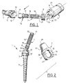
- Figure 1 is a partial perspective view before assembly, with enlarged scale, of a first embodiment of the device of spinal osteosynthesis according to the invention.
- FIG 2 is a partial perspective view of the device of the Figure 1, showing on an enlarged scale, a double bone anchoring element thread and a corresponding clamp for connection with a non-spinal rod shown, this bone anchoring element can in particular be a screw or a hook.
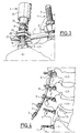
- Figure 3 is an enlarged perspective view of the device Figures 1 and 2 assembled and placed on a vertebral segment.
- Figure 4 is an anterolateral elevation view of a dorso-lumbar segment with an osteosynthesis device according to the invention during mounting, some of the connector stirrups equipping a vertebral rod being threaded on the threaded axes of the corresponding bone anchoring elements previously anchored in the vertebral bone structures.
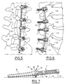
- Figure 5 is a posterior view of the dorso-lumbar segment of the Figure 4 and the corresponding device installed.
- FIG. 6 is an anterolateral view of the device of FIG. 5, showing the lumbar lordosis ensured by the bending of the vertebral rod.
- Figure 7 is a plan view of a bone anchor monobloc, without ball joint, able to equip the osteosynthesis device according to the invention.
- Figure 8 is a rear elevational view of a plate device of connection between the bone anchoring elements mounted on a segment thoracolumbar.
- Figure 9 is an elevational view in a sagittal plane of the device to plate of FIG. 8, comprising a bone anchoring element such as that in Figure 6.
- Figure 10 is a partial sectional elevation and sectional view enlarged assembly of a bone anchor, a stirrup connector and a clamping element according to the embodiment of FIGS. 1 to 4, ensuring a return of the bone anchoring element in the axis of the element of Tightening.
- Figure 11 is a schematic elevational view, on a reduced scale by compared to FIG. 10, of the whole of the corresponding device, illustrating the angular recall of the bone anchoring element in the axis of the tightening and threaded rod when tightening.
- Figure 12 is a partial view similar to Figure 10 of a variant of the device, modified so as to practically not ensure significant angular recall of the bone anchoring element during Tightening.
- Figure 13 is an enlarged perspective view of a second embodiment of the connector bracket of FIG. 2.
- Figure 14 is an elevational view on an enlarged scale of a second embodiment of a bone anchoring element of the device.
- Figure 15 is a partial sectional view and elevation of a mode of creation of a transverse connection system between two elements bone anchor, which can equip the device of FIGS. 1 to 14.
- Figure 16 is a top view of the cross link system in Figure 15.
- the spinal osteosynthesis device illustrated in Figures 1 to 6 includes several bone anchoring elements, constituted in the example described by bone anchoring elements 1 in respective vertebrae, a longitudinal connecting member between the bone anchoring elements 1 constituted by a vertebral rod 2, and stirrups 3 for connection between the bone anchors 1 and vertebral rods 2, at the rate of a stirrup 3 by bone anchor 1.
- Each element 1 comprises a conical threaded rod 4 for bone anchoring, a head 5 for gripping by a screwing tool 6, a mechanical threaded axis 7 extending the head 5.
- the device is completed by a nut 8 which can be screwed onto the threaded pin 7 to lock the connector bracket 3, the rod together vertebral 2 and the corresponding bone anchoring element 1.
- the gripping head 5 has a shape capable of cooperating with the screwing tool 6, for example a hexagonal contour as shown, adapted to cooperate with a female hexagonal imprint 9 of the tool 6.
- the axis 7 is provided with a terminal ball 11 for articulation in a hemispherical housing 12 of the head 5, in which this ball 11 can be maintained by various assembly and in particular crimping, welding, etc.
- the housing 12 substantially hemispherical allows the ball 11 to rotate and to be mobilized in all plans, thus authorizing an orientation multidirectional of the threaded axis 7.
- connection stirrup 3 are provided with means for blocking in rotation the axis 7 and its ball 11, during tightening or loosening of the nut 8, after introduction of the pin 7 into a corresponding hole 10 of passage through the connection bracket 3.
- these means comprise at least one male rotational stop geometry 13 formed on a flange 14 arranged between the ball joint 11 and the adjoining end of axis 7 and at least one second female rotational geometry illustrated by a flat 15 formed on the inside edge of the hole 10 of the stirrup 3.
- This second flat 15 is adapted so that it can be applied to the first flat 13 after sliding of the stirrup 3 on the threaded axis 7.
- the flange 14 thus has two stop geometries diametrically opposed 13, only one of these geometries 13 being visible in the drawings.
- the collar 14 thus provided with the two geometries 13 can be adjusted in the corresponding connector stirrup 3 if the assembly is used with a vertebral rod 2, or in a plate 16 having rotational stop geometries (edges of holes 38, 41, 43 in Figs. 8 and 9) similar 13 ( Figures 8 and 9) if a plate 16 is used in place of the rod 2 as a longitudinal connecting member between the screws 1.
- the axis 7 has a first threaded portion cylindrical 17, a narrowing 18 constituting an initiation zone of rupture, a second cylindrical threaded portion 19 extended by a part terminal 21 smooth and constituting a male form of suitable profile, by example in a half moon with a rotational stop geometry, hereinafter the flat 22 ( Figure 2).
- This male form 21 is adapted to be able to cooperate with a female shape 20 complementary to the tool 6, formed in the end of a sleeve 24 mounted to slide axially inside a socket 25, at the end of which the female imprint is arranged hexagonal 9 (figure 1).
- the rupture initiation zone 18 preferably has a stop geometry identical to flat 22. This arrangement makes it possible to lock in rotation of the ball joint 11, during an implant recovery operation, using tool 6.
- the socket of the male form 21 with its rotational stop geometry can be a flat 22 in the female form conjugated 20 with application of the flats 22 and 23 against each other, makes it possible to block the axis threaded 7 in rotation during the screwing of nut 8 on threaded portions 19 and 17 from axis 7.
- the axis 7 breaks into two parts. in order to remove the threaded portion 19.
- the second portion 19 having the function only guide the descent of the nut 8 to the stirrup 3 ( Figure 3).
- the nesting of the male 22 and female flats 23 of the sleeve 24 ensures the rotation of the ball joint 11 in its housing 12,
- the connector stirrup 3 is made up of two branches 26, 27 folded one on the other and separated by a longitudinal slot 28. the hole 10 of passage of the axis 7 being thus formed in the branches 26, 27 on either side of the slot 28.
- the two branches 26, 27 are connected by one or two connectors rounded 29 which delimits one or two cylindrical housings 31 in which can be introduced one or two cylindrical rods 2 ( Figure 13).
- FIGS. 10 and 11 illustrate in more detail the embodiment of the device which has just been described with reference to FIGS. 1 to 3.
- the sphere or ball 11 of the anchoring element bone 1 and the spherical cap 57 have centers of rotation respective R1 and R2, distinct and separated by a spacing S.
- the surface of the cap 57 of head 5 is hemispherical and interrupted in its polar region to receive the ball 11, and the spherical surface 55 associated with the stirrup 3, same radius of curvature as the surface of the hemispherical cap 57, completely covers the latter.
- the support taken on the upper part of the gripping head 5 ensures that connector stirrup system 3 and bone anchoring element 1 a function of recall of the latter in the axis XX of the clamping nut 8 and of the threaded rod 7 during the tightening operation by the element 8.
- the element 8 nut for example
- the element 8 whose skirt 8a comes apply to the conical wall 56 of the recess of the nut 8
- produces a tensile force F (figure 10)
- a torque C (figure 11) of return from the bone anchor 4 towards the longitudinal axis XX of the tightening 8 and of the threaded axis 7 by a force orthogonal to this axis.
- the spherical surface 55a only partially covers the spherical surface of the cap 57 because the spherical bearing 55a is interrupted clearly before the equator of the cap 57.
- the tensile force F produced by the tightening of the nut 8 immobilizes the connector stirrup 3 by surface contact, while retaining the orientation of the bone anchoring element 1.
- FIG. 13 illustrates an embodiment of the clip connector 3a wherein it comprises, on either side of the hole 10, two rounded fittings 29, 29 has delimiting two respective housings 31, 31 is adapted to receive longitudinal connecting members such as vertebral rods.
- Figure 14 illustrates a second embodiment of the element bone anchor, here constituted by a lamar hook 60 replacing the rod threaded 4 of the previous embodiment, the rest of the device also being similar to that of FIGS. 1 and 2, in particular the head 5 for gripping by a screwing tool 6 and the threaded axis 7.
- the lamar hook 6 consists of manner known per se by two clamps 60a, 60b with curved end and adjustable relative spacing.
- FIGS 15 and 16 illustrate a possible embodiment of a transverse connection system between bone anchoring elements (1 or 31 or 60).
- This connection system is formed by a pair of flared cups 58, 59, the bottom of which is pierced with an opening 66 for passage of the threaded axis 7.
- Each cup 58, 59 is made in one piece with a respective transverse tab 61, 62, the relative position, and therefore the spacing between the bowls, being adjustable. This adjustment can be obtained for example by means of a screw-nut assembly 63, 64 passing through an elongated lumen 65 of a tab 61 and a tapped hole of the second tab 62.
- Each cup 58, 59 is interposed between a connector bracket 3 (or 3 a ) and a corresponding clamping element 8, which is screwed into the bowl by resting on its conical wall 67, 68 by its conical skirt 8a.
- the orientability of the bone anchoring element 1 relative to the axis XX, with reminder (figures 10, 11) or without angular reminder (figure 12), can also be obtained with a similar geometrically complex recess made in a plate such as 16 ( Figures 8 and 9, orifice 41, 43).
- the axis 7 is oriented towards the connector 3 corresponding, previously mounted on a vertebral rod 2.
- the tool 6 makes it possible to block the axis 7 in rotation thanks to the sleeve 24 while the outer sleeve 25 makes it possible to screw the element of tightening 8 to its blocking position of the assembly, the geometry or geometries rotational stop 13 of the flange 14 being applied to the one or more corresponding rotational stop geometries 15 of stirrup 3.
- Figure 4 illustrates a reduction maneuver.
- the vertebral rod 2 was curved in the sagittal plane to reproduce the curvature of the lordosis that one wish to restore.
- the connector stirrups 3 are threaded on the rod 2 which, by through the stirrups 3, is guided step by step, but without effort, because the ball joint 11 of each bone anchoring element 1 makes it possible to direct the threaded axis extra pedicle 7 towards stirrup 3, before undertaking to bring rod 2 to spinal contact - namely in the example shown a dorso-lumbar segment: sacrum S and lumbar vertebrae L5, L4, L3, L2.
- the lowering of the stirrup 3 along the threaded axis 7 constituting the movable portion of the implant is made using the clamping element 8 (nut), using the key constituted by the tool 6, preventing the ball 11 from turning on itself as previously explained.
- Caliper 3 comes from its underside join the flange 14 suitably oriented, the two stop geometries rotational 22 (flats) 23 meet, thus ensuring the locking of the ball joint 11. Indeed, once facing the flat 15 of the stirrup 3, the flange 14 does not can no longer rotate around its axis.
- the two stop geometries rotational male 22 and female 15 are opposite one another, the ball 11 is blocks by itself. The implant became mono-axial.
- Postoperative X-rays of patients with scoliosis lumbar allow to verify that thanks to the osteosynthesis device according to the invention, the pedicle implants 1, seen from the front, are not in the same plan, and that the lumbar lordosis, (in profile) has been restored in a very satisfactory, with in particular the reappearance of a disc asymmetry physiological, essential to create anatomically conditions correct.
- FIG. 7 illustrates a second bone anchoring element 31 (a screw in this example) can be implemented in the device according to the invention, when the latter comprises a plate 16 ( Figures 8 and 9) or stirrups connectors 3.
- the bone anchoring element 31 comprises a threaded anchoring rod 32, a head 33 devoid of ball joint and thus making the piece screw.
- the head 33 consists of a transverse flange 34 and a shape 35 of grip for screwing with a suitable tool, e.g. a form hexagonal.
- a threaded axis 7 similar to that of the bone anchoring element 1 extends the head 33, the assembly being one piece.
- the plate 16 presents in gaze of the sacrum S a terminal part to a circular hole for passage of a single bone anchor 31, then at L5 for a second elongated portion 39 in which an oblong hole 41 is formed allowing to correlatively adjust the position of a bone anchoring element 31 between two positions; finally the plate 16 has a third part 42 of shape elongated in which is formed an oblong passage 43 delimiting three possible positions for the bone anchor element 1 depending on the fit necessary, thanks to three notches formed on the edges of passage 43.
- Plate 16 intended for three segments or spinal stages S, L5, L4, for example, can be replaced by a plate suitable for a number different floors.
- only one bone anchoring element is polyaxial, therefore with ball 11, the other bone anchoring elements 31 being monoaxial.
- Each hole (41 ...) of plate 16 can have the same profile as hole 10 of the bracket connector 3 for the passage of the bone anchoring element (Fig. 10). This profile ensures a recall function of the bone element towards the axis longitudinal of the clamping element and of the threaded axis 7 by a force orthogonal to this axis.
- the collar 34 located in the extension of the intrapedicular portion of the bone anchoring element 1, is fixed (FIGS. 8 and 9). It can usefully provide good support against the vertebra by a so-called effect "console", while a bone anchoring element 1 can usefully serve to segmentally reduce an angle between two bony structures of the spine contiguous.
- the polyaxial screw 1 is left movable at the start of the installation of the clamping element 8 along the threaded axis 7. Then the sleeve 24 with its half-moon shape 23 blocks the ball joint 11. By an adjusted movement, the bone anchor element 1 is thus positioned in one of the three orifices of the oblong hole 43.
- the pre-bending of the plate 16 allows the vertebra L4 to reposition itself in lordosis relative to the underlying vertebra, without compromise the locking of the plate 16 - anchor element couple bone 1, thanks to the tolerance of the patella 11.
Landscapes
- Health & Medical Sciences (AREA)
- Orthopedic Medicine & Surgery (AREA)
- Life Sciences & Earth Sciences (AREA)
- Neurology (AREA)
- Surgery (AREA)
- Heart & Thoracic Surgery (AREA)
- Engineering & Computer Science (AREA)
- Biomedical Technology (AREA)
- Nuclear Medicine, Radiotherapy & Molecular Imaging (AREA)
- Medical Informatics (AREA)
- Molecular Biology (AREA)
- Animal Behavior & Ethology (AREA)
- General Health & Medical Sciences (AREA)
- Public Health (AREA)
- Veterinary Medicine (AREA)
- Surgical Instruments (AREA)
- Prostheses (AREA)
Abstract
Selon l'invention, l'axe fileté (7) est pourvu d'une rotule terminale (11) d'articulation dans un logement (12) d'une calotte sphérique (57) de la tête (5) de préhension, permettant une orientation pluridirectionnelle de l'axe (7) et un positionnement de l'organe de liaison longitudinale (2 ; 16) adaptés à la configuration du segment vertébral (S, L5, ... L2) recevant les éléments d'ancrage osseux, et en ce que la rotule (11 ) est maintenue dans ledit logement (12) par sertissage du bord délimitant ce logement (12) autour de la rotule (11).
Description
- guidage de l'élément d'ancrage osseux 1, 31 par un instrument 6 normo-axant instantanément la partie pédiculaire 4, 32 de l'élément d'ancrage osseux 1 et son prolongement multiaxial 7.
- Possibilité de réduction monoplanaire ou combinée dans les trois plans.
- Affranchissement de certaines séquences opératoires.
- Réduction vertébrale par traction antéro-postérieure à l'aide de l'élément d'ancrage osseux, directement sans instrument complémentaire.
- Maítrise de l'orientabilité du système susceptible d'être conservée ou neutralisée indifféremment en fonction des exigences per-opératoires, grâce aux caractéristiques dimensionnelles et fonctionnelles des étriers connecteurs 3 (combinaison de la portée sphérique 55 ou 55a avec la calotte sphérique 57).
Claims (9)
- Dispositif d'ostéosynthèse rachidienne, comprenant au moins deux éléments d'ancrage osseux (1 ; 31) dans des corps de la structure osseuse du rachis respectifs (S, L5), au moins un organe (2 ; 16) de liaison longitudinale entre les éléments d'ancrage osseux, et des étriers (3) de connexion entre les éléments d'ancrage osseux, chaque élément d'ancrage osseux comportant une tête (5 ; 33) de préhension par un outil (6) de vissage, un axe fileté (7) prolongeant la tête de préhension, et un élément de serrage (8) pouvant être mis en place sur cet axe pour bloquer ensemble l'organe de liaison longitudinale et l'élément d'ancrage osseux correspondant, caractérisé en ce que l'axe fileté (7) est pourvu d'une rotule terminale (11) d'articulation dans un logement (12) d'une calotte sphérique (57) de la tête (5) de préhension, permettant une orientation pluridirectionnelle de l'axe (7) et un positionnement de l'organe de liaison longitudinale (2 ; 16) adaptés à la configuration du segment vertébral (S, L5, ... L2) recevant les éléments d'ancrage osseux, et en ce que la rotule (11) est maintenue dans ledit logement (12) par sertissage du bord délimitant ce logement (12) autour de la rotule (11).
- Dispositif selon la revendication 1, caractérisé en ce que le logement (12) est hémisphérique.
- Dispositif selon la revendication 1 ou la revendication 2, caractérisé en ce que l'organe de liaison longitudinale entre les éléments d'ancrage osseux (1) est une tige vertébrale (2) traversant les étriers (3) de connexion aux éléments d'ancrage osseux.
- Dispositif selon la revendication 3, caractérisé en ce que la surface de la calotte (57) de la tête (5) est hémisphérique et est interrompue dans la zone polaire pour recevoir la rotule (11), et en ce que la surface sphérique (55) associée de l'étrier (3) recouvre au moins partiellement la surface hémisphérique de la calotte (57).
- Dispositif selon la revendication 4, caractérisé en ce que l'étrier connecteur (3) présente une surface conique (56) d'appui de l'élément de serrage (8), raccordée à ladite surface sphérique (55).
- Dispositif selon l'une des revendications 1 à 5, caractérisé en ce que l'organe de liaison longitudinale entre les éléments d'ancrage osseux (1) et (31) est une plaque (16) dans laquelle sont ménagées des ouvertures cylindriques, et/ou oblongues (41, 43) délimitant différents emplacements possibles pour les éléments d'ancrage osseux et traversées par les axes filetés (7), sur lesquels sont mis en place les éléments de serrage (8) de blocage, et en ce que les ouvertures de la plaque (16) ont un profil similaire à celui du trou (10) de chaque étrier connecteur (3).
- Dispositif selon l'une des revendications 1 à 6, caractérisé en ce que l'extrémité de l'axe fileté (7) opposée à la rotule (11) est constituée d'une forme mâle (21) par exemple en demi-lune, adaptée pour coopérer avec une forme femelle complémentaire (23) d'un outil (6), afin de bloquer la rotule en rotation durant le vissage de l'élément de serrage (8) sur l'axe fileté (7).
- Dispositif selon l'une des revendications 1 à 7, caractérisé en ce que l'axe fileté (7) est pourvu d'un rétrécissement (18) délimitant deux zones filetées (17) et (19) de cet axe et constituant une amorce de rupture après assemblage et mise en place de l'élément de serrage s,ur l'étrier de connexion, ce rétrécissement permettant alors la cassure de l'axe (7).
- Dispositif selon l'une des revendications 1 à 9, caractérisé en ce qu'il comprend un système de liaison transversale entre des éléments d'ancrage osseux (1), formé par une paire de cuvettes (58, 59) chacune monobloc avec une patte (61, 62), la position relative et donc l'écartement entre les cuvettes étant réglable, par exemple au moyen d'un ensemble vis-écrou (63, 64) traversant une lumière allongée (65) d'une patte (61) et un trou taraudé de la deuxième patte (62).
Applications Claiming Priority (3)
| Application Number | Priority Date | Filing Date | Title |
|---|---|---|---|
| IE970411 IES77331B2 (en) | 1997-06-03 | 1997-06-03 | Pluridirectional and modulable vertebral osteosynthesis device of small overall size |
| IE970411 | 1997-06-03 | ||
| EP98929473A EP0986339B1 (fr) | 1997-06-03 | 1998-06-03 | Dispositif d'osteosynthese vertebrale pluridirectionnelle et modulable, a encombrement reduit |
Related Parent Applications (1)
| Application Number | Title | Priority Date | Filing Date |
|---|---|---|---|
| EP98929473A Division EP0986339B1 (fr) | 1997-06-03 | 1998-06-03 | Dispositif d'osteosynthese vertebrale pluridirectionnelle et modulable, a encombrement reduit |
Publications (3)
| Publication Number | Publication Date |
|---|---|
| EP1415602A2 true EP1415602A2 (fr) | 2004-05-06 |
| EP1415602A3 EP1415602A3 (fr) | 2005-07-06 |
| EP1415602B1 EP1415602B1 (fr) | 2007-10-24 |
Family
ID=11041500
Family Applications (3)
| Application Number | Title | Priority Date | Filing Date |
|---|---|---|---|
| EP03025168A Expired - Lifetime EP1415602B1 (fr) | 1997-06-03 | 1998-06-03 | Dispositif d'ostéosynthèse vertébrale pluridirectionelle et modulable, à encombrement réduit |
| EP98929473A Expired - Lifetime EP0986339B1 (fr) | 1997-06-03 | 1998-06-03 | Dispositif d'osteosynthese vertebrale pluridirectionnelle et modulable, a encombrement reduit |
| EP03025177A Expired - Lifetime EP1415603B1 (fr) | 1997-06-03 | 1998-06-03 | Dispositif d'ostéosynthèse vertébrale pluridirectionnelle et modulable, à encombrement réduit |
Family Applications After (2)
| Application Number | Title | Priority Date | Filing Date |
|---|---|---|---|
| EP98929473A Expired - Lifetime EP0986339B1 (fr) | 1997-06-03 | 1998-06-03 | Dispositif d'osteosynthese vertebrale pluridirectionnelle et modulable, a encombrement reduit |
| EP03025177A Expired - Lifetime EP1415603B1 (fr) | 1997-06-03 | 1998-06-03 | Dispositif d'ostéosynthèse vertébrale pluridirectionnelle et modulable, à encombrement réduit |
Country Status (9)
| Country | Link |
|---|---|
| US (2) | USRE42626E1 (fr) |
| EP (3) | EP1415602B1 (fr) |
| JP (1) | JP4399554B2 (fr) |
| CA (1) | CA2292748C (fr) |
| DE (3) | DE69826999T2 (fr) |
| ES (3) | ES2229509T3 (fr) |
| IE (1) | IES77331B2 (fr) |
| PT (3) | PT986339E (fr) |
| WO (1) | WO1998055038A1 (fr) |
Cited By (1)
| Publication number | Priority date | Publication date | Assignee | Title |
|---|---|---|---|---|
| WO2009135208A1 (fr) * | 2008-05-02 | 2009-11-05 | Warsaw Orthopedic, Inc. | Élément de liaison pour dispositif d'ostéosynthèse vertébrale et dispositif d'ostéosynthèse vertébrale qui le contient |
Families Citing this family (296)
| Publication number | Priority date | Publication date | Assignee | Title |
|---|---|---|---|---|
| US7201751B2 (en) | 1997-01-02 | 2007-04-10 | St. Francis Medical Technologies, Inc. | Supplemental spine fixation device |
| US7306628B2 (en) | 2002-10-29 | 2007-12-11 | St. Francis Medical Technologies | Interspinous process apparatus and method with a selectably expandable spacer |
| US6652527B2 (en) * | 1998-10-20 | 2003-11-25 | St. Francis Medical Technologies, Inc. | Supplemental spine fixation device and method |
| US6283967B1 (en) | 1999-12-17 | 2001-09-04 | Synthes (U.S.A.) | Transconnector for coupling spinal rods |
| FR2796546B1 (fr) * | 1999-07-23 | 2001-11-30 | Eurosurgical | Connecteur polyaxial pour implant rachidien |
| DE19944120B4 (de) * | 1999-09-15 | 2008-08-28 | Ulrich Gmbh & Co. Kg | Knochenschraube zur winkelvariablen Verbindung mit einem Längsträger |
| AU2006200772B2 (en) * | 2000-06-30 | 2009-04-02 | Stephen Ritland | Polyaxial connection device and method |
| AU2001280476B2 (en) * | 2000-06-30 | 2005-11-24 | Stephen Ritland | Polyaxial connection device and method |
| US7056321B2 (en) | 2000-08-01 | 2006-06-06 | Endius, Incorporated | Method of securing vertebrae |
| US7985247B2 (en) * | 2000-08-01 | 2011-07-26 | Zimmer Spine, Inc. | Methods and apparatuses for treating the spine through an access device |
| US7833250B2 (en) | 2004-11-10 | 2010-11-16 | Jackson Roger P | Polyaxial bone screw with helically wound capture connection |
| US6554831B1 (en) * | 2000-09-01 | 2003-04-29 | Hopital Sainte-Justine | Mobile dynamic system for treating spinal disorder |
| US6692434B2 (en) | 2000-09-29 | 2004-02-17 | Stephen Ritland | Method and device for retractor for microsurgical intermuscular lumbar arthrodesis |
| US7166073B2 (en) | 2000-09-29 | 2007-01-23 | Stephen Ritland | Method and device for microsurgical intermuscular spinal surgery |
| FR2816196B1 (fr) | 2000-11-07 | 2003-01-03 | Medicrea | Materiel d'arthrodese vertebrale |
| FR2816195B1 (fr) * | 2000-11-07 | 2003-01-03 | Medicrea | Materiel d'arthrodese vertebrale |
| US6802844B2 (en) * | 2001-03-26 | 2004-10-12 | Nuvasive, Inc | Spinal alignment apparatus and methods |
| US6887243B2 (en) | 2001-03-30 | 2005-05-03 | Triage Medical, Inc. | Method and apparatus for bone fixation with secondary compression |
| US6511481B2 (en) | 2001-03-30 | 2003-01-28 | Triage Medical, Inc. | Method and apparatus for fixation of proximal femoral fractures |
| FR2823095B1 (fr) * | 2001-04-06 | 2004-02-06 | Ldr Medical | Dispositif d'osteosynthese du rachis et procede de mise en place |
| US7235079B2 (en) | 2004-11-18 | 2007-06-26 | Acumed Llc | Composite bone fasteners |
| US8292926B2 (en) | 2005-09-30 | 2012-10-23 | Jackson Roger P | Dynamic stabilization connecting member with elastic core and outer sleeve |
| US8353932B2 (en) | 2005-09-30 | 2013-01-15 | Jackson Roger P | Polyaxial bone anchor assembly with one-piece closure, pressure insert and plastic elongate member |
| US7862587B2 (en) | 2004-02-27 | 2011-01-04 | Jackson Roger P | Dynamic stabilization assemblies, tool set and method |
| US10729469B2 (en) | 2006-01-09 | 2020-08-04 | Roger P. Jackson | Flexible spinal stabilization assembly with spacer having off-axis core member |
| US10258382B2 (en) | 2007-01-18 | 2019-04-16 | Roger P. Jackson | Rod-cord dynamic connection assemblies with slidable bone anchor attachment members along the cord |
| JP4249021B2 (ja) | 2001-09-28 | 2009-04-02 | リットランド、ステファン | ねじまたはフック多軸システム用コネクティング・ロッド、および使用方法 |
| US7261713B2 (en) | 2001-10-09 | 2007-08-28 | Synthes (Usa) | Adjustable fixator |
| FR2831048B1 (fr) * | 2001-10-18 | 2004-09-17 | Ldr Medical | Dispositif d'osteosynthese a approche progressive et procede de premontage |
| FR2833151B1 (fr) * | 2001-12-12 | 2004-09-17 | Ldr Medical | Implant d'ancrage osseux a tete polyaxiale |
| US7163538B2 (en) * | 2002-02-13 | 2007-01-16 | Cross Medical Products, Inc. | Posterior rod system |
| US20040006342A1 (en) * | 2002-02-13 | 2004-01-08 | Moti Altarac | Posterior polyaxial plate system for the spine |
| ATE476930T1 (de) | 2002-02-20 | 2010-08-15 | Stephen Ritland | Gerät zur verbindung von stielschrauben |
| FR2838041B1 (fr) * | 2002-04-04 | 2004-07-02 | Kiscomedica | Systeme d'osteosynthese rachidienne |
| US6966910B2 (en) | 2002-04-05 | 2005-11-22 | Stephen Ritland | Dynamic fixation device and method of use |
| JP4559848B2 (ja) | 2002-05-08 | 2010-10-13 | リトランド,ステイーヴン | 動的固定装置及びその使用法 |
| US6733502B2 (en) * | 2002-05-15 | 2004-05-11 | Cross Medical Products, Inc. | Variable locking spinal screw having a knurled collar |
| US6793678B2 (en) | 2002-06-27 | 2004-09-21 | Depuy Acromed, Inc. | Prosthetic intervertebral motion disc having dampening |
| FR2842093B1 (fr) * | 2002-07-12 | 2005-04-15 | Scient X | Dispositif d'ancrage osseux avec articulation spherique |
| US7955388B2 (en) * | 2006-11-01 | 2011-06-07 | Acumed Llc | Orthopedic connector system |
| US8876868B2 (en) | 2002-09-06 | 2014-11-04 | Roger P. Jackson | Helical guide and advancement flange with radially loaded lip |
| US7434220B2 (en) * | 2002-09-16 | 2008-10-07 | Clearcube Technology, Inc. | Distributed computing infrastructure including autonomous intelligent management system |
| US7549999B2 (en) | 2003-05-22 | 2009-06-23 | Kyphon Sarl | Interspinous process distraction implant and method of implantation |
| US20080234756A1 (en) * | 2002-11-19 | 2008-09-25 | John Sutcliffe | Pedicle Screw |
| WO2004075778A2 (fr) | 2003-02-25 | 2004-09-10 | Stephen Ritland | Dispositif a tige ajustable et connecteur, et son procede d'utilisation |
| EP1610700B1 (fr) * | 2003-03-26 | 2010-08-04 | Swiss Orthopedic Solutions SA | Plaque vissee verrouillable |
| US8540753B2 (en) | 2003-04-09 | 2013-09-24 | Roger P. Jackson | Polyaxial bone screw with uploaded threaded shank and method of assembly and use |
| US6964666B2 (en) * | 2003-04-09 | 2005-11-15 | Jackson Roger P | Polyaxial bone screw locking mechanism |
| US7621918B2 (en) | 2004-11-23 | 2009-11-24 | Jackson Roger P | Spinal fixation tool set and method |
| US7377923B2 (en) | 2003-05-22 | 2008-05-27 | Alphatec Spine, Inc. | Variable angle spinal screw assembly |
| WO2004110247A2 (fr) | 2003-05-22 | 2004-12-23 | Stephen Ritland | Guide intermusculaire pour l'insertion d'un ecarteur et procede d'utilisation |
| US8366753B2 (en) | 2003-06-18 | 2013-02-05 | Jackson Roger P | Polyaxial bone screw assembly with fixed retaining structure |
| US8936623B2 (en) | 2003-06-18 | 2015-01-20 | Roger P. Jackson | Polyaxial bone screw assembly |
| US7967850B2 (en) | 2003-06-18 | 2011-06-28 | Jackson Roger P | Polyaxial bone anchor with helical capture connection, insert and dual locking assembly |
| US7766915B2 (en) | 2004-02-27 | 2010-08-03 | Jackson Roger P | Dynamic fixation assemblies with inner core and outer coil-like member |
| US8092500B2 (en) | 2007-05-01 | 2012-01-10 | Jackson Roger P | Dynamic stabilization connecting member with floating core, compression spacer and over-mold |
| US7776067B2 (en) | 2005-05-27 | 2010-08-17 | Jackson Roger P | Polyaxial bone screw with shank articulation pressure insert and method |
| US8308772B2 (en) * | 2003-06-27 | 2012-11-13 | Medicrea Technologies | Vertebral osteosynthesis equipment |
| WO2005000135A1 (fr) * | 2003-06-27 | 2005-01-06 | Medicrea Technologies | Dispositif d'osteosynthese vertebrale |
| FR2856581B1 (fr) * | 2003-06-27 | 2005-08-19 | Medicrea | Materiel d'osteosynthese vertebrale |
| FR2856580B1 (fr) * | 2003-06-27 | 2006-03-17 | Medicrea | Materiel d'osteosynthese vertebrale |
| FR2857850B1 (fr) * | 2003-06-27 | 2005-08-19 | Medicrea International | Materiel d'osteosynthese vertebrale |
| FR2856579B1 (fr) * | 2003-06-27 | 2006-03-17 | Medicrea | Materiel d'osteosynthese vertebrale et procede de fabrication d'un organe d'ancrage osseux que comprend ce materiel |
| US7875060B2 (en) * | 2003-09-24 | 2011-01-25 | Spinefrontier, LLS | Multi-axial screw with a spherical landing |
| US7967826B2 (en) | 2003-10-21 | 2011-06-28 | Theken Spine, Llc | Connector transfer tool for internal structure stabilization systems |
| US7588575B2 (en) | 2003-10-21 | 2009-09-15 | Innovative Spinal Technologies | Extension for use with stabilization systems for internal structures |
| US11419642B2 (en) | 2003-12-16 | 2022-08-23 | Medos International Sarl | Percutaneous access devices and bone anchor assemblies |
| US7179261B2 (en) | 2003-12-16 | 2007-02-20 | Depuy Spine, Inc. | Percutaneous access devices and bone anchor assemblies |
| US7527638B2 (en) | 2003-12-16 | 2009-05-05 | Depuy Spine, Inc. | Methods and devices for minimally invasive spinal fixation element placement |
| US20060161260A1 (en) * | 2003-12-23 | 2006-07-20 | Gareth Thomas | Total wrist prosthesis |
| US7833251B1 (en) * | 2004-01-06 | 2010-11-16 | Nuvasive, Inc. | System and method for performing spinal fixation |
| FR2865373B1 (fr) * | 2004-01-27 | 2006-03-03 | Medicrea International | Materiel d'osteosynthese vertebrale |
| US8152810B2 (en) | 2004-11-23 | 2012-04-10 | Jackson Roger P | Spinal fixation tool set and method |
| US7160300B2 (en) | 2004-02-27 | 2007-01-09 | Jackson Roger P | Orthopedic implant rod reduction tool set and method |
| WO2005092218A1 (fr) | 2004-02-27 | 2005-10-06 | Jackson Roger P | Ensemble d'instruments de reduction de tige d'implant orthopedique et methode associee |
| US7547318B2 (en) * | 2004-03-19 | 2009-06-16 | Depuy Spine, Inc. | Spinal fixation element and methods |
| ATE532473T1 (de) * | 2004-03-26 | 2011-11-15 | Synthes Gmbh | Knochenschraube mit gelenk |
| US7524324B2 (en) | 2004-04-28 | 2009-04-28 | Kyphon Sarl | System and method for an interspinous process implant as a supplement to a spine stabilization implant |
| US7854752B2 (en) | 2004-08-09 | 2010-12-21 | Theken Spine, Llc | System and method for dynamic skeletal stabilization |
| US20060052783A1 (en) * | 2004-08-17 | 2006-03-09 | Dant Jack A | Polyaxial device for spine stabilization during osteosynthesis |
| US20060052786A1 (en) * | 2004-08-17 | 2006-03-09 | Zimmer Spine, Inc. | Polyaxial device for spine stabilization during osteosynthesis |
| US20060052784A1 (en) * | 2004-08-17 | 2006-03-09 | Zimmer Spine, Inc. | Polyaxial device for spine stabilization during osteosynthesis |
| DE502004009456D1 (de) * | 2004-08-20 | 2009-06-18 | Stryker Trauma Sa | Klemmelement und Gelenkelement |
| US7455639B2 (en) | 2004-09-20 | 2008-11-25 | Stephen Ritland | Opposing parallel bladed retractor and method of use |
| US7651502B2 (en) | 2004-09-24 | 2010-01-26 | Jackson Roger P | Spinal fixation tool set and method for rod reduction and fastener insertion |
| US7722654B2 (en) * | 2004-10-05 | 2010-05-25 | Warsaw Orthopedic, Inc. | Spinal implants with multi-axial anchor assembly and methods |
| US7794477B2 (en) | 2004-10-05 | 2010-09-14 | Warsaw Orthopedic, Inc. | Spinal implants and methods with extended multi-axial anchor assemblies |
| US7572280B2 (en) * | 2004-10-05 | 2009-08-11 | Warsaw Orthopedic, Inc. | Multi-axial anchor assemblies for spinal implants and methods |
| US8123782B2 (en) | 2004-10-20 | 2012-02-28 | Vertiflex, Inc. | Interspinous spacer |
| US8128662B2 (en) | 2004-10-20 | 2012-03-06 | Vertiflex, Inc. | Minimally invasive tooling for delivery of interspinous spacer |
| US8945183B2 (en) | 2004-10-20 | 2015-02-03 | Vertiflex, Inc. | Interspinous process spacer instrument system with deployment indicator |
| US8012207B2 (en) * | 2004-10-20 | 2011-09-06 | Vertiflex, Inc. | Systems and methods for posterior dynamic stabilization of the spine |
| US20100036423A1 (en) * | 2004-10-20 | 2010-02-11 | Stanley Kyle Hayes | Dynamic rod |
| US9023084B2 (en) | 2004-10-20 | 2015-05-05 | The Board Of Trustees Of The Leland Stanford Junior University | Systems and methods for stabilizing the motion or adjusting the position of the spine |
| US8317864B2 (en) | 2004-10-20 | 2012-11-27 | The Board Of Trustees Of The Leland Stanford Junior University | Systems and methods for posterior dynamic stabilization of the spine |
| US20090030465A1 (en) * | 2004-10-20 | 2009-01-29 | Moti Altarac | Dynamic rod |
| US9119680B2 (en) | 2004-10-20 | 2015-09-01 | Vertiflex, Inc. | Interspinous spacer |
| US8613747B2 (en) | 2004-10-20 | 2013-12-24 | Vertiflex, Inc. | Spacer insertion instrument |
| US8162985B2 (en) | 2004-10-20 | 2012-04-24 | The Board Of Trustees Of The Leland Stanford Junior University | Systems and methods for posterior dynamic stabilization of the spine |
| US7763074B2 (en) | 2004-10-20 | 2010-07-27 | The Board Of Trustees Of The Leland Stanford Junior University | Systems and methods for posterior dynamic stabilization of the spine |
| US8277488B2 (en) | 2004-10-20 | 2012-10-02 | Vertiflex, Inc. | Interspinous spacer |
| US8152837B2 (en) | 2004-10-20 | 2012-04-10 | The Board Of Trustees Of The Leland Stanford Junior University | Systems and methods for posterior dynamic stabilization of the spine |
| US8425559B2 (en) | 2004-10-20 | 2013-04-23 | Vertiflex, Inc. | Systems and methods for posterior dynamic stabilization of the spine |
| US9161783B2 (en) | 2004-10-20 | 2015-10-20 | Vertiflex, Inc. | Interspinous spacer |
| US8123807B2 (en) | 2004-10-20 | 2012-02-28 | Vertiflex, Inc. | Systems and methods for posterior dynamic stabilization of the spine |
| US8226690B2 (en) | 2005-07-22 | 2012-07-24 | The Board Of Trustees Of The Leland Stanford Junior University | Systems and methods for stabilization of bone structures |
| US7935134B2 (en) | 2004-10-20 | 2011-05-03 | Exactech, Inc. | Systems and methods for stabilization of bone structures |
| US20090228045A1 (en) * | 2004-10-20 | 2009-09-10 | Stanley Kyle Hayes | Dynamic rod |
| US8167944B2 (en) | 2004-10-20 | 2012-05-01 | The Board Of Trustees Of The Leland Stanford Junior University | Systems and methods for posterior dynamic stabilization of the spine |
| US8025680B2 (en) | 2004-10-20 | 2011-09-27 | Exactech, Inc. | Systems and methods for posterior dynamic stabilization of the spine |
| US8273108B2 (en) | 2004-10-20 | 2012-09-25 | Vertiflex, Inc. | Interspinous spacer |
| US8267969B2 (en) | 2004-10-20 | 2012-09-18 | Exactech, Inc. | Screw systems and methods for use in stabilization of bone structures |
| US8409282B2 (en) | 2004-10-20 | 2013-04-02 | Vertiflex, Inc. | Systems and methods for posterior dynamic stabilization of the spine |
| JP2008519656A (ja) | 2004-11-10 | 2008-06-12 | ロジャー・ピー・ジャクソン | 破断伸張部付の螺旋状案内及び前進フランジ |
| US8926672B2 (en) | 2004-11-10 | 2015-01-06 | Roger P. Jackson | Splay control closure for open bone anchor |
| US9216041B2 (en) | 2009-06-15 | 2015-12-22 | Roger P. Jackson | Spinal connecting members with tensioned cords and rigid sleeves for engaging compression inserts |
| US9980753B2 (en) | 2009-06-15 | 2018-05-29 | Roger P Jackson | pivotal anchor with snap-in-place insert having rotation blocking extensions |
| US8444681B2 (en) | 2009-06-15 | 2013-05-21 | Roger P. Jackson | Polyaxial bone anchor with pop-on shank, friction fit retainer and winged insert |
| WO2006057837A1 (fr) | 2004-11-23 | 2006-06-01 | Jackson Roger P | Structure d'accrochage pour outil de fixation spinale |
| US9168069B2 (en) | 2009-06-15 | 2015-10-27 | Roger P. Jackson | Polyaxial bone anchor with pop-on shank and winged insert with lower skirt for engaging a friction fit retainer |
| US8172855B2 (en) | 2004-11-24 | 2012-05-08 | Abdou M S | Devices and methods for inter-vertebral orthopedic device placement |
| EP2219538B1 (fr) | 2004-12-06 | 2022-07-06 | Vertiflex, Inc. | Instrument d'insertion d'un écarteur |
| US7591851B2 (en) | 2004-12-13 | 2009-09-22 | Kyphon Sarl | Inter-cervical facet implant and method |
| US7578833B2 (en) * | 2004-12-13 | 2009-08-25 | Dr. Robert S. Bray, Jr. | Bone fastener assembly for bone retention apparatus |
| WO2006069089A2 (fr) | 2004-12-21 | 2006-06-29 | Packaging Service Corporation Of Kentucky | Systeme de plaque cervicale |
| US7776072B2 (en) * | 2004-12-30 | 2010-08-17 | Barry Mark A | System and method for aligning vertebrae in the amelioration of aberrant spinal column deviation conditions |
| US9339301B2 (en) | 2004-12-30 | 2016-05-17 | Mark A. Barry | System and method for aligning vertebrae in the amelioration of aberrant spinal column deviation conditions |
| US7670358B2 (en) * | 2004-12-30 | 2010-03-02 | Barry Mark A | System and method for aligning vertebrae in the amelioration of aberrant spinal column deviation conditions |
| FR2880255B1 (fr) * | 2004-12-30 | 2013-07-05 | Neuro France Implants | Dispositif d'implant pour systeme d'osteosynthese vertebrale posterieure |
| US7901437B2 (en) | 2007-01-26 | 2011-03-08 | Jackson Roger P | Dynamic stabilization member with molded connection |
| US10076361B2 (en) | 2005-02-22 | 2018-09-18 | Roger P. Jackson | Polyaxial bone screw with spherical capture, compression and alignment and retention structures |
| US7828828B2 (en) * | 2005-04-14 | 2010-11-09 | Warsaw Orthopedic, Inc | Intervertebral joint |
| US7794481B2 (en) | 2005-04-22 | 2010-09-14 | Warsaw Orthopedic, Inc. | Force limiting coupling assemblies for spinal implants |
| US7695499B2 (en) * | 2005-04-29 | 2010-04-13 | Warsaw Orthopedic, Inc. | System, devices and method for augmenting existing fusion constructs |
| US7951198B2 (en) * | 2005-05-10 | 2011-05-31 | Acumed Llc | Bone connector with pivotable joint |
| US7862589B2 (en) * | 2005-05-24 | 2011-01-04 | Lanx, Inc. | Facet replacement |
| CA2615497C (fr) | 2005-07-19 | 2014-03-25 | Stephen Ritland | Tige d'extension permettant d'etendre un produit de fusion |
| US8523865B2 (en) * | 2005-07-22 | 2013-09-03 | Exactech, Inc. | Tissue splitter |
| US7625394B2 (en) * | 2005-08-05 | 2009-12-01 | Warsaw Orthopedic, Inc. | Coupling assemblies for spinal implants |
| US7628799B2 (en) | 2005-08-23 | 2009-12-08 | Aesculap Ag & Co. Kg | Rod to rod connector |
| EP1767161A1 (fr) * | 2005-09-22 | 2007-03-28 | Zimmer Spine, Inc. | Système de mise en forme d'une tige de fixation spinale |
| US8105368B2 (en) | 2005-09-30 | 2012-01-31 | Jackson Roger P | Dynamic stabilization connecting member with slitted core and outer sleeve |
| US7803174B2 (en) * | 2005-11-04 | 2010-09-28 | Warsaw Orthopedic, Inc. | Dorsal adjusting multi-rod connector |
| US7704271B2 (en) | 2005-12-19 | 2010-04-27 | Abdou M Samy | Devices and methods for inter-vertebral orthopedic device placement |
| US8029545B2 (en) * | 2006-02-07 | 2011-10-04 | Warsaw Orthopedic Inc. | Articulating connecting member and anchor systems for spinal stabilization |
| EP1820461B1 (fr) | 2006-02-21 | 2009-08-05 | Stryker Trauma SA | Elément de serrage et d'articulation |
| US8025681B2 (en) | 2006-03-29 | 2011-09-27 | Theken Spine, Llc | Dynamic motion spinal stabilization system |
| US20070288012A1 (en) * | 2006-04-21 | 2007-12-13 | Dennis Colleran | Dynamic motion spinal stabilization system and device |
| US7799055B2 (en) * | 2006-07-07 | 2010-09-21 | Warsaw Orthopedic, Inc. | Minimal spacing spinal stabilization device and method |
| US7959564B2 (en) | 2006-07-08 | 2011-06-14 | Stephen Ritland | Pedicle seeker and retractor, and methods of use |
| US8845726B2 (en) | 2006-10-18 | 2014-09-30 | Vertiflex, Inc. | Dilator |
| US20090082775A1 (en) * | 2006-10-25 | 2009-03-26 | Moti Altarac | Spondylolisthesis reduction system and method |
| US8096996B2 (en) | 2007-03-20 | 2012-01-17 | Exactech, Inc. | Rod reducer |
| US8162990B2 (en) * | 2006-11-16 | 2012-04-24 | Spine Wave, Inc. | Multi-axial spinal fixation system |
| US8105382B2 (en) | 2006-12-07 | 2012-01-31 | Interventional Spine, Inc. | Intervertebral implant |
| EP2088945A4 (fr) | 2006-12-08 | 2010-02-17 | Roger P Jackson | Systeme d'instruments pour implants rachidiens dynamiques |
| US20080147128A1 (en) * | 2006-12-15 | 2008-06-19 | Zimmer Technology, Inc. | Cannulated bone screw and cannulated driver for the implantation thereof |
| US7744632B2 (en) | 2006-12-20 | 2010-06-29 | Aesculap Implant Systems, Inc. | Rod to rod connector |
| US7789895B2 (en) * | 2006-12-26 | 2010-09-07 | Warsaw Orthopedic, Inc. | Sacral reconstruction fixation device |
| US8366745B2 (en) | 2007-05-01 | 2013-02-05 | Jackson Roger P | Dynamic stabilization assembly having pre-compressed spacers with differential displacements |
| US8475498B2 (en) | 2007-01-18 | 2013-07-02 | Roger P. Jackson | Dynamic stabilization connecting member with cord connection |
| US8012177B2 (en) | 2007-02-12 | 2011-09-06 | Jackson Roger P | Dynamic stabilization assembly with frusto-conical connection |
| EP2155121B1 (fr) | 2007-04-16 | 2015-06-17 | Vertiflex, Inc. | Espaceur interspinal |
| US8979904B2 (en) | 2007-05-01 | 2015-03-17 | Roger P Jackson | Connecting member with tensioned cord, low profile rigid sleeve and spacer with torsion control |
| US10383660B2 (en) | 2007-05-01 | 2019-08-20 | Roger P. Jackson | Soft stabilization assemblies with pretensioned cords |
| CA2721898A1 (fr) * | 2007-05-25 | 2009-12-18 | Exactech, Inc. | Tige dynamique |
| WO2008153827A1 (fr) | 2007-05-31 | 2008-12-18 | Jackson Roger P | Élément de raccord à stabilisation dynamique avec noyau solide précontraint |
| US8114134B2 (en) | 2007-06-05 | 2012-02-14 | Spartek Medical, Inc. | Spinal prosthesis having a three bar linkage for motion preservation and dynamic stabilization of the spine |
| US8083772B2 (en) | 2007-06-05 | 2011-12-27 | Spartek Medical, Inc. | Dynamic spinal rod assembly and method for dynamic stabilization of the spine |
| WO2008151091A1 (fr) | 2007-06-05 | 2008-12-11 | Spartek Medical, Inc. | Système de tiges déflectrices pour un système d'implants spinaux à stabilisation dynamique et préservation du mouvement, et procédé correspondant |
| US8105356B2 (en) | 2007-06-05 | 2012-01-31 | Spartek Medical, Inc. | Bone anchor with a curved mounting element for a dynamic stabilization and motion preservation spinal implantation system and method |
| US8048115B2 (en) | 2007-06-05 | 2011-11-01 | Spartek Medical, Inc. | Surgical tool and method for implantation of a dynamic bone anchor |
| US8092501B2 (en) | 2007-06-05 | 2012-01-10 | Spartek Medical, Inc. | Dynamic spinal rod and method for dynamic stabilization of the spine |
| US8021396B2 (en) | 2007-06-05 | 2011-09-20 | Spartek Medical, Inc. | Configurable dynamic spinal rod and method for dynamic stabilization of the spine |
| FR2916956B1 (fr) | 2007-06-08 | 2012-12-14 | Ldr Medical | Cage intersomatique,prothese intervertebrale,dispositif d'ancrage et instrumentation d'implantation |
| US8313515B2 (en) | 2007-06-15 | 2012-11-20 | Rachiotek, Llc | Multi-level spinal stabilization system |
| US8900307B2 (en) | 2007-06-26 | 2014-12-02 | DePuy Synthes Products, LLC | Highly lordosed fusion cage |
| US8911477B2 (en) | 2007-10-23 | 2014-12-16 | Roger P. Jackson | Dynamic stabilization member with end plate support and cable core extension |
| US20090125032A1 (en) * | 2007-11-14 | 2009-05-14 | Gutierrez Robert C | Rod removal instrument |
| FR2924326B1 (fr) * | 2007-11-30 | 2010-12-10 | Medicrea International | Materiel chirurgical, notamment materiel d'osteosynthese vertebrale |
| CA2711955C (fr) | 2008-01-15 | 2016-05-17 | Vertiflex, Inc. | Ecarteur interepineux |
| AU2009205896A1 (en) | 2008-01-17 | 2009-07-23 | Synthes Gmbh | An expandable intervertebral implant and associated method of manufacturing the same |
| US8211155B2 (en) | 2008-02-26 | 2012-07-03 | Spartek Medical, Inc. | Load-sharing bone anchor having a durable compliant member and method for dynamic stabilization of the spine |
| US8083775B2 (en) | 2008-02-26 | 2011-12-27 | Spartek Medical, Inc. | Load-sharing bone anchor having a natural center of rotation and method for dynamic stabilization of the spine |
| US20100030224A1 (en) | 2008-02-26 | 2010-02-04 | Spartek Medical, Inc. | Surgical tool and method for connecting a dynamic bone anchor and dynamic vertical rod |
| US8097024B2 (en) | 2008-02-26 | 2012-01-17 | Spartek Medical, Inc. | Load-sharing bone anchor having a deflectable post and method for stabilization of the spine |
| US8267979B2 (en) | 2008-02-26 | 2012-09-18 | Spartek Medical, Inc. | Load-sharing bone anchor having a deflectable post and axial spring and method for dynamic stabilization of the spine |
| US8337536B2 (en) | 2008-02-26 | 2012-12-25 | Spartek Medical, Inc. | Load-sharing bone anchor having a deflectable post with a compliant ring and method for stabilization of the spine |
| US8333792B2 (en) | 2008-02-26 | 2012-12-18 | Spartek Medical, Inc. | Load-sharing bone anchor having a deflectable post and method for dynamic stabilization of the spine |
| US8057517B2 (en) | 2008-02-26 | 2011-11-15 | Spartek Medical, Inc. | Load-sharing component having a deflectable post and centering spring and method for dynamic stabilization of the spine |
| US8016861B2 (en) | 2008-02-26 | 2011-09-13 | Spartek Medical, Inc. | Versatile polyaxial connector assembly and method for dynamic stabilization of the spine |
| US9060813B1 (en) | 2008-02-29 | 2015-06-23 | Nuvasive, Inc. | Surgical fixation system and related methods |
| FR2929100B1 (fr) * | 2008-03-25 | 2011-04-15 | Medicrea International | Materiel d'arthrodese vertebrale |
| BRPI0910325A8 (pt) | 2008-04-05 | 2019-01-29 | Synthes Gmbh | implante intervertebral expansível |
| FR2930720B1 (fr) * | 2008-05-02 | 2011-10-21 | Warsaw Orthopedic Inc | Element de liaison entre un element longitudinal d'un dispositif d'osteosynthese vertebrale et une vertebre, dispositif d'osteosynthese vertebrale le comprenant et outil pour sa pose |
| CA2739997C (fr) | 2008-08-01 | 2013-08-13 | Roger P. Jackson | Element longitudinal de liaison avec cordons tendus gaines |
| US8308775B2 (en) * | 2008-10-14 | 2012-11-13 | Medicrea International | Method for rotating a vertebra or vertebrae |
| US9526620B2 (en) | 2009-03-30 | 2016-12-27 | DePuy Synthes Products, Inc. | Zero profile spinal fusion cage |
| US8998959B2 (en) | 2009-06-15 | 2015-04-07 | Roger P Jackson | Polyaxial bone anchors with pop-on shank, fully constrained friction fit retainer and lock and release insert |
| US11229457B2 (en) | 2009-06-15 | 2022-01-25 | Roger P. Jackson | Pivotal bone anchor assembly with insert tool deployment |
| CN103826560A (zh) | 2009-06-15 | 2014-05-28 | 罗杰.P.杰克逊 | 具有套接杆和带摩擦配合压缩套爪的带翼插件的多轴骨锚 |
| US9668771B2 (en) | 2009-06-15 | 2017-06-06 | Roger P Jackson | Soft stabilization assemblies with off-set connector |
| FR2946859B1 (fr) | 2009-06-22 | 2012-11-09 | Medicrea International | Materiel d'osteosynthese vertebrale. |
| US20110166610A1 (en) * | 2009-08-07 | 2011-07-07 | Moti Altarac | Systems and methods for stabilization of bone structures, including thorocolumbar stabilization systems and methods |
| AU2010303934B2 (en) | 2009-10-05 | 2014-03-27 | Roger P. Jackson | Polyaxial bone anchor with non-pivotable retainer and pop-on shank, some with friction fit |
| US20110093014A1 (en) * | 2009-10-19 | 2011-04-21 | Zimmer Spine, Inc. | Rod with Removable End and Inserter Therefor |
| WO2011069000A2 (fr) | 2009-12-02 | 2011-06-09 | Spartek Medical, Inc. | Prothèse spinale à profil mince incorporant un ancrage osseux ayant un montant déformable et une tige spinale composite |
| US8764806B2 (en) | 2009-12-07 | 2014-07-01 | Samy Abdou | Devices and methods for minimally invasive spinal stabilization and instrumentation |
| US9393129B2 (en) | 2009-12-10 | 2016-07-19 | DePuy Synthes Products, Inc. | Bellows-like expandable interbody fusion cage |
| EP2512357B1 (fr) | 2009-12-15 | 2016-07-13 | Vertiflex, Inc. | Écarteur vertébral pour vertèbres cervicales et autres vertèbres, et systèmes associés |
| FR2956803B1 (fr) * | 2010-03-01 | 2013-06-07 | Medicrea International | Materiel d'osteosynthese vertebrale |
| US8617216B2 (en) * | 2010-04-05 | 2013-12-31 | David L. Brumfield | Fully-adjustable bone fixation device |
| US9198696B1 (en) | 2010-05-27 | 2015-12-01 | Nuvasive, Inc. | Cross-connector and related methods |
| US20110307018A1 (en) | 2010-06-10 | 2011-12-15 | Spartek Medical, Inc. | Adaptive spinal rod and methods for stabilization of the spine |
| US9763678B2 (en) | 2010-06-24 | 2017-09-19 | DePuy Synthes Products, Inc. | Multi-segment lateral cage adapted to flex substantially in the coronal plane |
| US8979860B2 (en) | 2010-06-24 | 2015-03-17 | DePuy Synthes Products. LLC | Enhanced cage insertion device |
| AU2011271465B2 (en) | 2010-06-29 | 2015-03-19 | Synthes Gmbh | Distractible intervertebral implant |
| FR2964031B1 (fr) | 2010-09-01 | 2013-07-12 | Medicrea International | Ensemble d'osteosynthese vertebrale forme par un materiel d'osteosynthese vertebrale et par des instruments de pose de ce materiel |
| JP2013540468A (ja) | 2010-09-08 | 2013-11-07 | ロジャー・ピー・ジャクソン | 弾性部および非弾性部を有する動的固定化部材 |
| US9402732B2 (en) | 2010-10-11 | 2016-08-02 | DePuy Synthes Products, Inc. | Expandable interspinous process spacer implant |
| EP2635212A4 (fr) | 2010-11-02 | 2013-11-20 | Jackson Roger P | Dispositif polyaxial d'ancrage osseux à tige fixée par pression et à élément de retenue pivotant |
| US9186184B2 (en) * | 2011-02-14 | 2015-11-17 | Pioneer Surgical Technology, Inc. | Spinal fixation system and method |
| US9247964B1 (en) | 2011-03-01 | 2016-02-02 | Nuasive, Inc. | Spinal Cross-connector |
| US9387013B1 (en) | 2011-03-01 | 2016-07-12 | Nuvasive, Inc. | Posterior cervical fixation system |
| WO2012128825A1 (fr) | 2011-03-24 | 2012-09-27 | Jackson Roger P | Ancrage osseux polyaxial avec articulation composée et tige enclipsable |
| FR2978343B1 (fr) | 2011-07-25 | 2013-08-23 | Medicrea International | Organe d'ancrage pour materiel d'osteosynthese vertebrale |
| US8845728B1 (en) | 2011-09-23 | 2014-09-30 | Samy Abdou | Spinal fixation devices and methods of use |
| US8911479B2 (en) | 2012-01-10 | 2014-12-16 | Roger P. Jackson | Multi-start closures for open implants |
| US8430916B1 (en) | 2012-02-07 | 2013-04-30 | Spartek Medical, Inc. | Spinal rod connectors, methods of use, and spinal prosthesis incorporating spinal rod connectors |
| US20130226240A1 (en) | 2012-02-22 | 2013-08-29 | Samy Abdou | Spinous process fixation devices and methods of use |
| FR2988992B1 (fr) | 2012-04-04 | 2015-03-20 | Medicrea International | Materiel d'osteosynthese vertebrale |
| FR2989264B1 (fr) | 2012-04-11 | 2014-05-09 | Medicrea International | Materiel d'osteosynthese vertebrale |
| US8771319B2 (en) | 2012-04-16 | 2014-07-08 | Aesculap Implant Systems, Llc | Rod to rod cross connector |
| US8828056B2 (en) | 2012-04-16 | 2014-09-09 | Aesculap Implant Systems, Llc | Rod to rod cross connector |
| WO2014018098A1 (fr) | 2012-07-26 | 2014-01-30 | DePuy Synthes Products, LLC | Implant expansible |
| US9198767B2 (en) | 2012-08-28 | 2015-12-01 | Samy Abdou | Devices and methods for spinal stabilization and instrumentation |
| US20140067069A1 (en) | 2012-08-30 | 2014-03-06 | Interventional Spine, Inc. | Artificial disc |
| US9320617B2 (en) | 2012-10-22 | 2016-04-26 | Cogent Spine, LLC | Devices and methods for spinal stabilization and instrumentation |
| US8911478B2 (en) | 2012-11-21 | 2014-12-16 | Roger P. Jackson | Splay control closure for open bone anchor |
| US10058354B2 (en) | 2013-01-28 | 2018-08-28 | Roger P. Jackson | Pivotal bone anchor assembly with frictional shank head seating surfaces |
| US8852239B2 (en) | 2013-02-15 | 2014-10-07 | Roger P Jackson | Sagittal angle screw with integral shank and receiver |
| US9717601B2 (en) | 2013-02-28 | 2017-08-01 | DePuy Synthes Products, Inc. | Expandable intervertebral implant, system, kit and method |
| US9522070B2 (en) | 2013-03-07 | 2016-12-20 | Interventional Spine, Inc. | Intervertebral implant |
| US9743959B2 (en) | 2013-03-14 | 2017-08-29 | Atlas Spine, Inc. | Low profile spinal fixation system |
| US9668789B2 (en) | 2013-03-15 | 2017-06-06 | Ebi, Llc | Reduction instrument, surgical assembly including a reduction instrument and related method |
| US9675303B2 (en) | 2013-03-15 | 2017-06-13 | Vertiflex, Inc. | Visualization systems, instruments and methods of using the same in spinal decompression procedures |
| FR3004636A1 (fr) * | 2013-04-19 | 2014-10-24 | Medicrea International | Ensemble de reprise pour materiel d'osteosynthese vertebrale |
| FR3010628B1 (fr) | 2013-09-18 | 2015-10-16 | Medicrea International | Procede permettant de realiser la courbure ideale d'une tige d'un materiel d'osteosynthese vertebrale destinee a etayer la colonne vertebrale d'un patient |
| FR3012030B1 (fr) | 2013-10-18 | 2015-12-25 | Medicrea International | Procede permettant de realiser la courbure ideale d'une tige d'un materiel d'osteosynthese vertebrale destinee a etayer la colonne vertebrale d'un patient |
| US9566092B2 (en) | 2013-10-29 | 2017-02-14 | Roger P. Jackson | Cervical bone anchor with collet retainer and outer locking sleeve |
| US9717533B2 (en) | 2013-12-12 | 2017-08-01 | Roger P. Jackson | Bone anchor closure pivot-splay control flange form guide and advancement structure |
| US9451993B2 (en) | 2014-01-09 | 2016-09-27 | Roger P. Jackson | Bi-radial pop-on cervical bone anchor |
| FR3019981B1 (fr) | 2014-04-17 | 2020-12-11 | Medicrea Int | Materiel d'osteosynthese vertebrale |
| FR3019982A1 (fr) | 2014-04-17 | 2015-10-23 | Medicrea International | Materiel d'osteosynthese vertebrale permettant de realiser l'ancrage iliaque d'une barre vertebrale |
| EP3139848A4 (fr) | 2014-05-07 | 2018-06-13 | Vertiflex, Inc. | Systèmes de décompression du nerf spinal, systèmes de dilatation, et leurs procédés d'utilisation |
| US10064658B2 (en) | 2014-06-04 | 2018-09-04 | Roger P. Jackson | Polyaxial bone anchor with insert guides |
| US9597119B2 (en) | 2014-06-04 | 2017-03-21 | Roger P. Jackson | Polyaxial bone anchor with polymer sleeve |
| FR3027208B1 (fr) | 2014-10-15 | 2016-12-23 | Medicrea Int | Materiel d'osteosynthese vertebrale |
| US11426290B2 (en) | 2015-03-06 | 2022-08-30 | DePuy Synthes Products, Inc. | Expandable intervertebral implant, system, kit and method |
| FR3035318B1 (fr) | 2015-04-24 | 2017-05-19 | Medicrea Int | Materiel d'osteosynthese vertebrale |
| US9913727B2 (en) | 2015-07-02 | 2018-03-13 | Medos International Sarl | Expandable implant |
| US10857003B1 (en) | 2015-10-14 | 2020-12-08 | Samy Abdou | Devices and methods for vertebral stabilization |
| AU2016349705B2 (en) | 2015-11-04 | 2021-07-29 | Medicrea International | Methods and Apparatus for spinal reconstructive surgery and measuring spinal length and intervertebral spacing, tension and rotation |
| FR3049453B1 (fr) | 2016-03-30 | 2018-04-27 | Medicrea International | Procede de fabrication d'un implant, notamment vertebral ou intervertebral, et implant obtenu par ce procede |
| CN109640889B (zh) | 2016-06-28 | 2021-07-30 | Eit 新兴移植技术股份有限公司 | 可扩张的角度可调节式关节运动椎间保持架 |
| JP6995789B2 (ja) | 2016-06-28 | 2022-01-17 | イーアイティー・エマージング・インプラント・テクノロジーズ・ゲーエムベーハー | 拡張可能かつ角度調節可能な椎間ケージ |
| US10744000B1 (en) | 2016-10-25 | 2020-08-18 | Samy Abdou | Devices and methods for vertebral bone realignment |
| US10973648B1 (en) | 2016-10-25 | 2021-04-13 | Samy Abdou | Devices and methods for vertebral bone realignment |
| US10537436B2 (en) | 2016-11-01 | 2020-01-21 | DePuy Synthes Products, Inc. | Curved expandable cage |
| WO2018109556A1 (fr) | 2016-12-12 | 2018-06-21 | Medicrea International | Systèmes et procédés pour des implants rachidiens spécifiques au patient |
| US10888433B2 (en) | 2016-12-14 | 2021-01-12 | DePuy Synthes Products, Inc. | Intervertebral implant inserter and related methods |
| JP7165668B2 (ja) | 2017-04-21 | 2022-11-04 | メディクレア インターナショナル | 1種または複数の患者特異的脊椎インプラントを開発するためのシステム |
| US10398563B2 (en) | 2017-05-08 | 2019-09-03 | Medos International Sarl | Expandable cage |
| US11344424B2 (en) | 2017-06-14 | 2022-05-31 | Medos International Sarl | Expandable intervertebral implant and related methods |
| US10940016B2 (en) | 2017-07-05 | 2021-03-09 | Medos International Sarl | Expandable intervertebral fusion cage |
| US10918422B2 (en) | 2017-12-01 | 2021-02-16 | Medicrea International | Method and apparatus for inhibiting proximal junctional failure |
| US11179248B2 (en) | 2018-10-02 | 2021-11-23 | Samy Abdou | Devices and methods for spinal implantation |
| US11446156B2 (en) | 2018-10-25 | 2022-09-20 | Medos International Sarl | Expandable intervertebral implant, inserter instrument, and related methods |
| US12564447B2 (en) | 2019-04-02 | 2026-03-03 | Medicrea International | Systems, methods, and devices for developing patient-specific spinal implants, treatments, operations, and/or procedures |
| US11925417B2 (en) | 2019-04-02 | 2024-03-12 | Medicrea International | Systems, methods, and devices for developing patient-specific spinal implants, treatments, operations, and/or procedures |
| US11877801B2 (en) | 2019-04-02 | 2024-01-23 | Medicrea International | Systems, methods, and devices for developing patient-specific spinal implants, treatments, operations, and/or procedures |
| US11944385B2 (en) | 2019-04-02 | 2024-04-02 | Medicrea International | Systems and methods for medical image analysis |
| US11769251B2 (en) | 2019-12-26 | 2023-09-26 | Medicrea International | Systems and methods for medical image analysis |
| US11426286B2 (en) | 2020-03-06 | 2022-08-30 | Eit Emerging Implant Technologies Gmbh | Expandable intervertebral implant |
| US12171470B2 (en) | 2020-07-31 | 2024-12-24 | Mazor Robotics Ltd. | Surgical fixation systems, methods, and devices |
| US11850160B2 (en) | 2021-03-26 | 2023-12-26 | Medos International Sarl | Expandable lordotic intervertebral fusion cage |
| US11752009B2 (en) | 2021-04-06 | 2023-09-12 | Medos International Sarl | Expandable intervertebral fusion cage |
| US11712270B2 (en) * | 2021-05-17 | 2023-08-01 | Warsaw Orthopedic, Inc. | Quick lock clamp constructs and associated methods |
| CN113456199A (zh) * | 2021-07-29 | 2021-10-01 | 上海市浦东新区人民医院 | 治疗骨盆后环骨折脱位的多维内固定装置及方法 |
| US11331125B1 (en) * | 2021-10-07 | 2022-05-17 | Ortho Inventions, Llc | Low profile rod-to-rod coupler |
| EP4426216B1 (fr) | 2022-02-15 | 2025-06-04 | Boston Scientific Neuromodulation Corporation | Espaceur interépineux et systèmes utilisant l'espaceur interépineux |
| US12090064B2 (en) | 2022-03-01 | 2024-09-17 | Medos International Sarl | Stabilization members for expandable intervertebral implants, and related systems and methods |
| FR3136149B1 (fr) * | 2022-06-01 | 2024-09-06 | Paul Fayada | Dispositif de stabilisation vertébrale |
| US12433646B2 (en) | 2023-02-21 | 2025-10-07 | Boston Scientific Neuromodulation Corporation | Interspinous spacer with actuator locking arrangements and methods and systems |
| US12390340B2 (en) | 2023-03-15 | 2025-08-19 | Boston Scientific Neuromodulation Corporation | Interspinous spacer with a range of deployment positions and methods and systems |
| FR3153734B1 (fr) | 2023-10-04 | 2025-10-03 | Paul Fayada | Dispositif de stabilisation vertébrale |
Family Cites Families (16)
| Publication number | Priority date | Publication date | Assignee | Title |
|---|---|---|---|---|
| US2190585A (en) * | 1936-08-22 | 1940-02-13 | Armstrong Bros Tool Co | C clamp |
| DE3614101C1 (de) * | 1986-04-25 | 1987-10-22 | Juergen Prof Dr Med Harms | Pedikelschraube |
| US5304179A (en) * | 1993-06-17 | 1994-04-19 | Amei Technologies Inc. | System and method for installing a spinal fixation system at variable angles |
| US5628740A (en) * | 1993-12-23 | 1997-05-13 | Mullane; Thomas S. | Articulating toggle bolt bone screw |
| US5474551A (en) * | 1994-11-18 | 1995-12-12 | Smith & Nephew Richards, Inc. | Universal coupler for spinal fixation |
| FR2731344B1 (fr) * | 1995-03-06 | 1997-08-22 | Dimso Sa | Instrumentation rachidienne notamment pour tige |
| US5591166A (en) * | 1995-03-27 | 1997-01-07 | Smith & Nephew Richards, Inc. | Multi angle bone bolt |
| DE19512709A1 (de) * | 1995-04-08 | 1996-10-10 | Rehder Guenther | Prothesen-Halteeinrichtung |
| DE29509566U1 (de) * | 1995-06-10 | 1995-08-24 | ZF Lemförder Metallwaren AG, 49448 Lemförde | Axialgelenk für ein Gestänge in Kraftfahrzeugen |
| FR2748387B1 (fr) * | 1996-05-13 | 1998-10-30 | Stryker France Sa | Dispositif de fixation osseuse, en particulier au sacrum, en osteosynthese du rachis |
| US5800435A (en) * | 1996-10-09 | 1998-09-01 | Techsys, Llc | Modular spinal plate for use with modular polyaxial locking pedicle screws |
| US5735851A (en) * | 1996-10-09 | 1998-04-07 | Third Millennium Engineering, Llc | Modular polyaxial locking pedicle screw |
| US5891145A (en) * | 1997-07-14 | 1999-04-06 | Sdgi Holdings, Inc. | Multi-axial screw |
| EP0923908B1 (fr) * | 1997-12-17 | 2003-04-23 | Robert Lange | Appareil pour stabiliser certaines vertèbres du rachis |
| US5984924A (en) * | 1998-10-07 | 1999-11-16 | Isola Implants, Inc. | Bone alignment system having variable orientation bone anchors |
| US7163538B2 (en) * | 2002-02-13 | 2007-01-16 | Cross Medical Products, Inc. | Posterior rod system |
-
1997
- 1997-06-03 IE IE970411 patent/IES77331B2/en not_active IP Right Cessation
-
1998
- 1998-06-03 ES ES98929473T patent/ES2229509T3/es not_active Expired - Lifetime
- 1998-06-03 EP EP03025168A patent/EP1415602B1/fr not_active Expired - Lifetime
- 1998-06-03 CA CA002292748A patent/CA2292748C/fr not_active Expired - Fee Related
- 1998-06-03 ES ES03025168T patent/ES2295496T3/es not_active Expired - Lifetime
- 1998-06-03 PT PT98929473T patent/PT986339E/pt unknown
- 1998-06-03 DE DE69826999T patent/DE69826999T2/de not_active Expired - Lifetime
- 1998-06-03 JP JP50172899A patent/JP4399554B2/ja not_active Expired - Fee Related
- 1998-06-03 US US10/629,788 patent/USRE42626E1/en not_active Expired - Lifetime
- 1998-06-03 EP EP98929473A patent/EP0986339B1/fr not_active Expired - Lifetime
- 1998-06-03 US US09/445,176 patent/US6267765B1/en not_active Ceased
- 1998-06-03 PT PT03025177T patent/PT1415603E/pt unknown
- 1998-06-03 DE DE69838626T patent/DE69838626T2/de not_active Expired - Lifetime
- 1998-06-03 EP EP03025177A patent/EP1415603B1/fr not_active Expired - Lifetime
- 1998-06-03 PT PT03025168T patent/PT1415602E/pt unknown
- 1998-06-03 DE DE69839406T patent/DE69839406T2/de not_active Expired - Lifetime
- 1998-06-03 ES ES03025177T patent/ES2304482T3/es not_active Expired - Lifetime
- 1998-06-03 WO PCT/FR1998/001119 patent/WO1998055038A1/fr not_active Ceased
Cited By (2)
| Publication number | Priority date | Publication date | Assignee | Title |
|---|---|---|---|---|
| WO2009135208A1 (fr) * | 2008-05-02 | 2009-11-05 | Warsaw Orthopedic, Inc. | Élément de liaison pour dispositif d'ostéosynthèse vertébrale et dispositif d'ostéosynthèse vertébrale qui le contient |
| FR2930718A1 (fr) * | 2008-05-02 | 2009-11-06 | Warsaw Orthopedic Inc | Element de liaison d'un dispositif d'osteosynthese vertebrale, et dispositif d'osteosynthese vertebrale le comprenant |
Also Published As
| Publication number | Publication date |
|---|---|
| USRE42626E1 (en) | 2011-08-16 |
| DE69838626D1 (de) | 2007-12-06 |
| IES970411A2 (en) | 1997-12-03 |
| US6267765B1 (en) | 2001-07-31 |
| CA2292748C (fr) | 2008-01-29 |
| EP1415602B1 (fr) | 2007-10-24 |
| PT986339E (pt) | 2005-01-31 |
| EP0986339B1 (fr) | 2004-10-13 |
| JP2002510998A (ja) | 2002-04-09 |
| EP0986339A1 (fr) | 2000-03-22 |
| JP4399554B2 (ja) | 2010-01-20 |
| ES2229509T3 (es) | 2005-04-16 |
| ES2295496T3 (es) | 2008-04-16 |
| PT1415603E (pt) | 2008-06-09 |
| DE69826999D1 (de) | 2004-11-18 |
| DE69826999T2 (de) | 2005-10-13 |
| ES2304482T3 (es) | 2008-10-16 |
| WO1998055038A1 (fr) | 1998-12-10 |
| EP1415603B1 (fr) | 2008-04-23 |
| DE69839406T2 (de) | 2009-05-20 |
| DE69838626T2 (de) | 2008-08-28 |
| PT1415602E (pt) | 2008-01-30 |
| EP1415603A3 (fr) | 2005-07-06 |
| EP1415602A3 (fr) | 2005-07-06 |
| CA2292748A1 (fr) | 1998-12-10 |
| IES77331B2 (en) | 1997-12-03 |
| DE69839406D1 (de) | 2008-06-05 |
| EP1415603A2 (fr) | 2004-05-06 |
Similar Documents
| Publication | Publication Date | Title |
|---|---|---|
| EP0986339B1 (fr) | Dispositif d'osteosynthese vertebrale pluridirectionnelle et modulable, a encombrement reduit | |
| CA2215485C (fr) | Instrumentation rachidienne notamment pour tige | |
| EP1185209B1 (fr) | Implant pour dispositif d'osteosynthese notamment du rachis | |
| EP0971639B1 (fr) | Dispositif d'osteosynthese du rachis a fixation de tige intervertebrale desaxee | |
| EP1075224B1 (fr) | Systeme d'osteosynthese rachidienne avec moyens de serrage notamment pour une fixation anterieure | |
| EP1339337B1 (fr) | Dispositif de fixation d'une tige et d'une tete de vis a symetrie spherique | |
| EP1708631B1 (fr) | Materiel d osteosynthese vertebrale | |
| EP1199993B1 (fr) | Element de fixation et ancillaire pour la stabilisation des vertebres | |
| EP0645986B1 (fr) | Appareil de traitement du rachis | |
| FR2796545A1 (fr) | Liaison poly-axiale pour systeme d'osteosynthese, notamment pour le rachis | |
| FR2831420A1 (fr) | Appareil de maintien du rachis a assemblage par coincement | |
| FR2836368A1 (fr) | Dispositif de liaison sequentiel | |
| FR2781359A1 (fr) | Materiel d'osteosynthese rachidienne | |
| EP1578289A1 (fr) | Dispositif a plaque anterieure pour maintien du rachis | |
| FR2715825A1 (fr) | Tige de liaison auto-cintrable pour fixateur de rachis. | |
| FR2781663A1 (fr) | Dispositif d'osteosynthese rachidienne | |
| FR2857850A1 (fr) | Materiel d'osteosynthese vertebrale | |
| FR2989264A1 (fr) | Materiel d'osteosynthese vertebrale | |
| FR2887756A1 (fr) | Instrument pour le deplacement d'une vertebre | |
| WO1995032676A1 (fr) | Implant pour dispositif d'osteosynthese | |
| EP4477165B1 (fr) | Système de fixation sacrée et ensemble comprenant un tel système | |
| FR3080018A1 (fr) | Ensemble de triangulation permettant le redressement de vertebres, et systeme d’osteosynthese rachidienne comprenant de tels ensembles | |
| EP2858584B1 (fr) | Implant ilio-sacre de connexion a un systeme d'osteosynthese rachidienne | |
| FR2870713A1 (fr) | Implant pour dispositif d'osteosynthese du rachis, et ensemble forme par cet implant, un connecteur et un ecrou | |
| FR3153734A1 (fr) | Dispositif de stabilisation vertébrale |
Legal Events
| Date | Code | Title | Description |
|---|---|---|---|
| PUAI | Public reference made under article 153(3) epc to a published international application that has entered the european phase |
Free format text: ORIGINAL CODE: 0009012 |
|
| 17P | Request for examination filed |
Effective date: 20031104 |
|
| AC | Divisional application: reference to earlier application |
Ref document number: 0986339 Country of ref document: EP Kind code of ref document: P |
|
| AK | Designated contracting states |
Kind code of ref document: A2 Designated state(s): CH DE ES FR GB IT LI LU NL PT |
|
| PUAL | Search report despatched |
Free format text: ORIGINAL CODE: 0009013 |
|
| AK | Designated contracting states |
Kind code of ref document: A3 Designated state(s): CH DE ES FR GB IT LI LU NL PT |
|
| AKX | Designation fees paid |
Designated state(s): CH DE ES FR GB IT LI LU NL PT |
|
| RAP1 | Party data changed (applicant data changed or rights of an application transferred) |
Owner name: TAYLOR, JEAN Owner name: MEDICREA TECHNOLOGIES |
|
| RIN1 | Information on inventor provided before grant (corrected) |
Inventor name: MEDICREA TECHNOLOGIES Inventor name: TAYLOR, JEAN |
|
| RAP1 | Party data changed (applicant data changed or rights of an application transferred) |
Owner name: MEDICREA TECHNOLOGIES |
|
| RIN1 | Information on inventor provided before grant (corrected) |
Inventor name: TAYLOR, JEAN Inventor name: VILARET, BERNARD |
|
| GRAP | Despatch of communication of intention to grant a patent |
Free format text: ORIGINAL CODE: EPIDOSNIGR1 |
|
| GRAS | Grant fee paid |
Free format text: ORIGINAL CODE: EPIDOSNIGR3 |
|
| GRAA | (expected) grant |
Free format text: ORIGINAL CODE: 0009210 |
|
| AC | Divisional application: reference to earlier application |
Ref document number: 0986339 Country of ref document: EP Kind code of ref document: P |
|
| AK | Designated contracting states |
Kind code of ref document: B1 Designated state(s): CH DE ES FR GB IT LI LU NL PT |
|
| REG | Reference to a national code |
Ref country code: GB Ref legal event code: FG4D Free format text: NOT ENGLISH |
|
| REG | Reference to a national code |
Ref country code: CH Ref legal event code: EP |
|
| REF | Corresponds to: |
Ref document number: 69838626 Country of ref document: DE Date of ref document: 20071206 Kind code of ref document: P |
|
| REG | Reference to a national code |
Ref country code: PT Ref legal event code: SC4A Free format text: AVAILABILITY OF NATIONAL TRANSLATION Effective date: 20080121 |
|
| REG | Reference to a national code |
Ref country code: CH Ref legal event code: NV Representative=s name: ABREMA AGENCE BREVET ET MARQUES, GANGUILLET |
|
| GBT | Gb: translation of ep patent filed (gb section 77(6)(a)/1977) |
Effective date: 20080116 |
|
| REG | Reference to a national code |
Ref country code: ES Ref legal event code: FG2A Ref document number: 2295496 Country of ref document: ES Kind code of ref document: T3 |
|
| PLBE | No opposition filed within time limit |
Free format text: ORIGINAL CODE: 0009261 |
|
| STAA | Information on the status of an ep patent application or granted ep patent |
Free format text: STATUS: NO OPPOSITION FILED WITHIN TIME LIMIT |
|
| 26N | No opposition filed |
Effective date: 20080725 |
|
| PGFP | Annual fee paid to national office [announced via postgrant information from national office to epo] |
Ref country code: NL Payment date: 20090623 Year of fee payment: 12 |
|
| PGFP | Annual fee paid to national office [announced via postgrant information from national office to epo] |
Ref country code: LU Payment date: 20090616 Year of fee payment: 12 |
|
| REG | Reference to a national code |
Ref country code: NL Ref legal event code: V1 Effective date: 20110101 |
|
| PG25 | Lapsed in a contracting state [announced via postgrant information from national office to epo] |
Ref country code: NL Free format text: LAPSE BECAUSE OF NON-PAYMENT OF DUE FEES Effective date: 20110101 |
|
| PG25 | Lapsed in a contracting state [announced via postgrant information from national office to epo] |
Ref country code: LU Free format text: LAPSE BECAUSE OF NON-PAYMENT OF DUE FEES Effective date: 20100603 |
|
| PGFP | Annual fee paid to national office [announced via postgrant information from national office to epo] |
Ref country code: FR Payment date: 20140516 Year of fee payment: 17 |
|
| REG | Reference to a national code |
Ref country code: FR Ref legal event code: PLFP Year of fee payment: 18 |
|
| PGFP | Annual fee paid to national office [announced via postgrant information from national office to epo] |
Ref country code: IT Payment date: 20150623 Year of fee payment: 18 |
|
| PGFP | Annual fee paid to national office [announced via postgrant information from national office to epo] |
Ref country code: GB Payment date: 20150717 Year of fee payment: 18 Ref country code: DE Payment date: 20150713 Year of fee payment: 18 Ref country code: ES Payment date: 20150730 Year of fee payment: 18 Ref country code: CH Payment date: 20150707 Year of fee payment: 18 |
|
| PGFP | Annual fee paid to national office [announced via postgrant information from national office to epo] |
Ref country code: PT Payment date: 20151104 Year of fee payment: 18 |
|
| REG | Reference to a national code |
Ref country code: DE Ref legal event code: R119 Ref document number: 69838626 Country of ref document: DE |
|
| REG | Reference to a national code |
Ref country code: CH Ref legal event code: PL |
|
| PG25 | Lapsed in a contracting state [announced via postgrant information from national office to epo] |
Ref country code: PT Free format text: LAPSE BECAUSE OF NON-PAYMENT OF DUE FEES Effective date: 20161205 |
|
| GBPC | Gb: european patent ceased through non-payment of renewal fee |
Effective date: 20160603 |
|
| REG | Reference to a national code |
Ref country code: FR Ref legal event code: ST Effective date: 20170228 |
|
| PG25 | Lapsed in a contracting state [announced via postgrant information from national office to epo] |
Ref country code: LI Free format text: LAPSE BECAUSE OF NON-PAYMENT OF DUE FEES Effective date: 20160630 Ref country code: DE Free format text: LAPSE BECAUSE OF NON-PAYMENT OF DUE FEES Effective date: 20170103 Ref country code: CH Free format text: LAPSE BECAUSE OF NON-PAYMENT OF DUE FEES Effective date: 20160630 Ref country code: FR Free format text: LAPSE BECAUSE OF NON-PAYMENT OF DUE FEES Effective date: 20160630 |
|
| PG25 | Lapsed in a contracting state [announced via postgrant information from national office to epo] |
Ref country code: GB Free format text: LAPSE BECAUSE OF NON-PAYMENT OF DUE FEES Effective date: 20160603 |
|
| PG25 | Lapsed in a contracting state [announced via postgrant information from national office to epo] |
Ref country code: IT Free format text: LAPSE BECAUSE OF NON-PAYMENT OF DUE FEES Effective date: 20160603 |
|
| PG25 | Lapsed in a contracting state [announced via postgrant information from national office to epo] |
Ref country code: ES Free format text: LAPSE BECAUSE OF NON-PAYMENT OF DUE FEES Effective date: 20160604 |
|
| REG | Reference to a national code |
Ref country code: ES Ref legal event code: FD2A Effective date: 20180625 |