EP1415687B1 - Integriertes Führungssystem einer Skibindung - Google Patents
Integriertes Führungssystem einer Skibindung Download PDFInfo
- Publication number
- EP1415687B1 EP1415687B1 EP03021703A EP03021703A EP1415687B1 EP 1415687 B1 EP1415687 B1 EP 1415687B1 EP 03021703 A EP03021703 A EP 03021703A EP 03021703 A EP03021703 A EP 03021703A EP 1415687 B1 EP1415687 B1 EP 1415687B1
- Authority
- EP
- European Patent Office
- Prior art keywords
- guide
- ski
- functional element
- elements
- holding
- Prior art date
- Legal status (The legal status is an assumption and is not a legal conclusion. Google has not performed a legal analysis and makes no representation as to the accuracy of the status listed.)
- Expired - Lifetime
Links
Images


Classifications
-
- A—HUMAN NECESSITIES
- A63—SPORTS; GAMES; AMUSEMENTS
- A63C—SKATES; SKIS; ROLLER SKATES; DESIGN OR LAYOUT OF COURTS, RINKS OR THE LIKE
- A63C9/00—Ski bindings
- A63C9/003—Non-swivel sole plate fixed on the ski
-
- A—HUMAN NECESSITIES
- A63—SPORTS; GAMES; AMUSEMENTS
- A63C—SKATES; SKIS; ROLLER SKATES; DESIGN OR LAYOUT OF COURTS, RINKS OR THE LIKE
- A63C5/00—Skis or snowboards
- A63C5/12—Making thereof; Selection of particular materials
- A63C5/128—A part for the binding being integrated within the board structure, e.g. plate, rail, insert
Definitions
- the invention relates to a in the construction of a sliding board, in particular a ski, integrated guide system for a functional element of a binding, wherein the guide system consists of a pair of extending in the ski longitudinal direction and spaced apart in the cross direction Skibercardi guide elements.
- the invention further relates to a gliding board, in particular a ski, having a guide system, which is arranged on its upper side and integrated in the structure of the ski, for a functional element of a binding, consisting of a pair of guide elements extending in the longitudinal direction of the ski and spaced apart in the transverse direction.
- the sliding boards which are provided according to these applications with a foamed core, have guide elements with anchoring elements, which are involved in the foaming of the core and held by the hardened foam in the sliding board.
- the guide system here consists of a pair of rails, which are connected via at least one molded dowel or dowel section by a Dübelharm- or anchoring to the sliding board body. The attachment of the rails takes place on the already finished sliding board and thus replaces only the otherwise usual screw fastening.
- the object is achieved by an inventively executed guide system, in which one of the guide elements for a play in the horizontal and vertical direction play holding the functional element and the other guide element for a play-free holding the functional element is designed only in the vertical direction.
- one of the two guide elements is the "leading" guide element, which ensures the exact guidance of the functional element backlash-free and non-clamping, the second "compensating" guide allows the possibly required lateral movement margin for tolerance compensation.
- the cooperating construction site such as functional and management elements
- the guide element holding the functional elements in the vertical and in the horizontal direction can be designed such that it runs in the longitudinal direction of the ski Guide strip which is encompassed by a preferably U-shaped sliding element of the functional element.
- a support projection needs to be provided on the functional element.
- the second functional element holding only in the vertical direction guide element is also very easy to execute.
- this guide element has a single guide bar which can be grasped by a U-shaped sliding element with horizontal play.
- executed guide systems or guide elements can be readily integrated into the structure of a ski, for example, they are anchored in the foam material of the core already in the production of the sliding board.
- a guide system according to the invention since it is important in this embodiment to be able to compensate for manufacturing tolerances.
- Fig. 1 to 3 cross-sections through different embodiments of a ski with a guide system for binding parts.
- a guide element 4, 14 (Fig. 1), 4 ', 14' (Fig. 2) and 4 ", 14" (Fig a guide member 4, 14, 4 ', 14', 4 ", 14" are those which, during ski construction, ie ski production, can be installed or integrated in the ski 1.
- the fastening or anchoring elements 2 provided for this purpose are only indicated in the drawing figures
- the anchoring elements 2 can be those which comprise components of the guide elements 4, 14, 4 ', 14', 4 ", 14 "are not and when foaming Skikerns are involved and held by the cured foam.
- the type of integration or integration of the guide elements 4, 14, 4 ', 14', 4 ", 14" is not the subject of the invention and can also be done in other ways. In this case, it is also possible to proceed in such a way that the guide elements 4, 14, 4 ', 14', 4 ", 14" are subsequently attached to screw-in fastening or anchoring elements 2, finished skis 1, screwed on, for example plugged on and the like become.
- the "leading" guide element 4 on the right in the drawing figure has a base part 4a and a guide part 4b with a lateral guide strip 4c pointing to the ski side edges and parallel to them.
- the support or base plate 3 is provided on its inner side with a sliding profile 13 cooperating with this guide element 4, which has on the inside of the guide element 4 a support lug 13a pointing in the direction of the ski upper side and an approximately U-shaped sliding element 13b on the outside the guide rail 4c surrounds.
- the support lug 13a and the sliding member 13b are adapted with respect to their dimensions to the guide part 4b of the guide element 4, that the support or base plate 3 on the guide element 4 play and clamping free pushed and slidably guided in the longitudinal direction.
- the support or base plate 3 is here held both vertically (perpendicular to the ski top) and in the horizontal, lateral directions (in Skiquerides).
- the second left-hand guide element 14 in FIG. 1 also has a base part 14a, a guide part 14b and a guide strip 14c.
- the sliding profile 23 of the support or base plate 3 also has a U-shaped sliding element 23b, which surrounds the guide rail 14c.
- Guide rail 14c and sliding member 23b are designed such that provided between the guide member 14 and the U-shaped sliding member 23b provided gaps or exemptions 5, 5 'in Skiquerides the desired tolerance compensation. Accordingly, the supporting or base plate 3 is indeed secured or held in the vertical direction in the region of the "compensating" guide element 14, in the horizontal direction is sufficient compensation for manufacturing tolerances given by a horizontal movement between the guide element 14 and support or base plate. 3 is allowed.
- the right-hand guide element 4 ' is provided with a base part 4'a, a guide part 4'b and two guide strips 4'c.
- a sliding profile 13' is provided, which has two approximately U-shaped sliding elements 13'b, which surround the two guide rails 4'c.
- the cooperating components are again coordinated with respect to their dimensions and dimensions to one another such that the support or base plate 3 'on the guide element 4' play and clamping free pushed, slidable in the ski longitudinal direction and is held both in the vertical and in the horizontal direction.
- the second, "compensating" guide element 14 ' also consists of a base part 14'a, a guide part 14'b and a single guide rail 14'c, which, based on the ski side edge, on the outside of the guide element 14' is provided and by a sliding profile 23rd 'With a U-shaped sliding member 23' b of the support or base plate 3 'is overlapped.
- Columns or exemptions 5, 5 'between the U-shaped sliding element 23' b and the guide element 14 ' ensure the compensation of manufacturing tolerances in this embodiment as well.
- the support or base plate 3 'on the guide member 14' held without play.
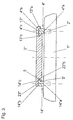
- Fig. 3 shows an embodiment in which the right in the drawing figure, "leading" guide element 4 "in reversal to the embodiment shown in Fig. 1 next to a base part 4" a, a guide part 4 “b and pointing inward to the ski center Guide bar 4 "c, which by a sliding profile 13" of the support or base plate 3 "by means of a likewise U-shaped sliding element 13" b can be overlapped or overlapped .
- On the outside of the guide element 4 " is only a support lug 13" a of the slide 13 "on.
- the cooperating components of support or base plate 3 "and guide element 4" are coordinated so that in a tolerance and play-free guidance of the support or base plate 3 "on the guide element 4" the support or base plate 3 "both in is held vertically and horizontally.
- the guide element 14 "shown on the left in FIG. 3 has, in addition to a base part 14" a, a guide part 14 "b and a guide rail 14" c projecting from this to the center of the ski.
- a U-shaped sliding element 23 “b of a sliding profile 23" of the support or base plate 3 "surrounds the guide rail 14" c and holds the base plate 3 "on the guide element 14" in the vertical direction.
- Columns or exemptions 5, 5 ' permit in the horizontal direction a relative movement between the support or base plate 3 "and the guide element 14".
- the invention is not limited to the illustrated embodiments. So it is particularly possible to realize the invention in other sliding boards, such as snowboards. Concerning the design of the guide elements and the sliding profiles cooperating with these on the binding parts or support or base plates, there are a variety of other ways to vertical in the region of the one guide element of the pair of guide elements, the binding member or the support or base plate and to hold in the horizontal direction and in the region of the second guide element only in the vertical direction and with a certain play in the horizontal direction.
Landscapes
- Fittings On The Vehicle Exterior For Carrying Loads, And Devices For Holding Or Mounting Articles (AREA)
- Basic Packing Technique (AREA)
- Ropes Or Cables (AREA)
- Vibration Prevention Devices (AREA)
Description
- Die Erfindung betrifft ein in den Aufbau eines Gleitbrettes, insbesondere eines Skis, integriertes Führungssystem für ein Funktionselement einer Bindung, wobei das Führungssystem aus einem Paar von sich in Skilängsrichtung erstreckenden und in Skiquerrichtung voneinander beabstandeten Führungselementen besteht. Die Erfindung betrifft ferner ein Gleitbrett, insbesondere einen Ski, mit einem auf seiner Oberseite angeordneten, in den Aufbau des Skis integrierten Führungssystem für ein Funktionselement einer Bindung, bestehend aus einem Paar von in Skilängsrichtung verlaufenden und in Skiquerrichtung voneinander beabstandeten Führungselementen.
- Derartige Führungssysteme bzw. derartige Gleitbretter sind in der noch nicht veröffentlichten österreichischen Gebrauchsmusteranmeldung Nr. GM 632/2002 und der noch nicht veröffentlichten europäischen Patentanmeldung Nr. 02015378.9 der Anmelderin beschrieben. Die Gleitbretter, welche gemäß diesen Anmeldungen mit einem geschäumten Kern versehen sind, weisen Führungselemente mit Verankerungselementen auf, die beim Schäumvorgang des Kern eingebunden und durch den ausgehärteten Schaum im Gleitbrett gehalten werden.
- Eine weitere Ausführung eines Führungssystems ist aus der EP-A-1 161 072 bekannt. Das Führungssystem besteht hier aus einem Paar von Profilschienen, die über wenigstens einen angeformten Dübel oder Dübelabschnitt durch eine Dübelverbindung- bzw. verankerung mit dem Gleitbrettkörper verbunden werden. Die Befestigung der Profilschienen erfolgt am bereits fertigen Gleitbrett und ersetzt somit lediglich die ansonsten übliche Schraubenbefestigung.
- Bei Führungssystemen, die bereits während der Herstellung des Skis in den Skiaufbau eingebundene bzw. integrierte Bestandteile aufweisen, besteht das Problem, dass gewisse Fertigungstoleranzen, beispielsweise auch hinsichtlich des gegenseitigen Abstandes der in den Skiaufbau integrierten Bestandteile der Führungselemente des Führungssystems, nur schwer bzw. mit großem Aufwand herstellungstechnisch vermieden werden können. Das kann nun zur Folge haben, dass die auf das Führungssystem aufzuschiebenden und hier gleitbeweglich zu führenden Funktionselemente der Bindung, beispielsweise Trag- bzw. Grundplatten, entweder ein unerwünschten Spiel gegenüber dem Führungssystem aufweisen oder am Führungssystem leicht verklemmen.
- Hier setzt nun die Erfindung ein, deren Aufgabe darin besteht, dieses Problem zu beseitigen.
- Gelöst wird die gestellte Aufgabe durch ein erfindungsgemäß ausgeführtes Führungssystem, bei dem eines der Führungselemente für ein in horizontaler und vertikaler Richtung spielfreies Halten des Funktionselementes und das andere Führungselement für ein spielfreies Halten des Funktionselementes lediglich in vertikaler Richtung ausgeführt ist.
- Die gestellte Aufgabe wird auch durch ein erfindungsgemäß ausgeführtes Gleitbrett gelöst, welches mit einem derartigen Führungssystem versehen ist.
- Gemäß der Erfindung ist somit eines der beiden Führungselemente das "führende" Führungselement, welches die exakte Führung des Funktionselementes spielfrei und klemmungsfrei gewährleistet, das zweite "ausgleichende" Führungselement gestattet den gegebenenfalls erforderlichen seitlichen Bewegungsspielraum zum Toleranzausgleich.
- Ein weiterer Vorteil der Erfindung besteht darin, dass die zusammenwirkenden Bautelle, wie Funktions- und Fuhrungseiemente, weiterhin einfach, zweckmäßig und funktionell aufgebaut sein können. So kann beispielsweise das das Funktionselemente in vertikaler und in horizontaler Richtung haltende Führungselement so ausgeführt sein, dass es eine in Skilängsrichtung verlaufende Führungsleiste aufweist, die von einem vorzugsweise U-förmigen Gleitelement des Funktionselementes umgreifbar ist. Um das Funktionselement an diesem Führungselement in horizontaler Richtung zu halten, braucht beispielsweise lediglich ein Stützansatz am Funktionselement vorgesehen werden.
- Das zweite das Funktionselement nur in vertikaler Richtung haltende Führungselement ist ebenfalls sehr einfach ausführbar. Bei einer bevorzugten Ausführung ist vorgesehen, dass dieses Führungselement eine einzige von einem U-förmigen Gleitelement mit horizontalem Spiel umgreifbare Führungsleiste aufweist.
- Erfindungsgemäß ausgeführte Führungssysteme bzw. Führungselemente lassen sich ohne weiteres auch in den Aufbau eines Skis integrieren, indem sie beispielsweise im Schaummaterial des Kerns bereits bei der Herstellung des Gleitbrettes verankert werden. Gerade bei einer derartigen Ausführungen des Gleitbrettes, ist es besonders vorteilhaft ein erfindungsgemäßes Führungssystem zu verwenden, da es gerade bei dieser Ausführung wichtig ist, Fertigungstoleranzen ausgleichen zu können.
- Weitere Merkmale, Vorteile und Einzelheiten der Erfindung werden nun anhand der Zeichnung, die ein Ausführungsbeispiel darstellt, näher beschrieben. Dabei zeigen,
- Fig. 1 bis 3 Querschnitte durch unterschiedliche Ausführungsformen eines Skis mit einem Führungssystem für Bindungsteile.
- In sämtlichen drei Zeichnungsfiguren sind die Außenkonturen eines Skis 1 dargestellt, auf dessen Oberseite ein Paar von Führungselementen 4, 14 (Fig. 1), 4', 14' (Fig. 2) und 4", 14" (Fig. 3) für ein Bindungsteil, beispielsweise eine Trag- bzw. Grundplatte 3, 3', 3", vorgesehen ist. Die Führungselemente 4, 14, 4', 14', 4", 14" sind solche, die während des Skiaufbaues, also der Skiherstellung, in den Ski 1 eingebaut bzw. integriert werden. Die dazu vorgesehenen Befestigungs- oder Verankerungselemente 2 sind in den Zeichnungsfiguren nur angedeutet. Die Verankerungselemente 2 können solche sein, die Bestandteile der Führungselemente 4, 14, 4', 14', 4", 14" sind und beim Schäumen des nicht dargestellten Skikerns eingebunden werden und durch den ausgehärteten Schaum gehalten werden. Diesbezüglich wird beispielsweise auf die noch nicht veröffentlichte österreichischen Gebrauchsmusteranmeldung Nr. GM 632/2002 der Anmelderin hingewiesen. Die Art der Einbindung bzw. Integration der Führungselemente 4, 14, 4', 14', 4", 14" ist nicht Gegenstand der Erfindung und kann auch auf andere Weise erfolgen. Dabei kann auch so vorgegangen werden, dass die Führungselemente 4, 14, 4', 14', 4", 14" an während der Skiproduktion eingebundenen Befestigungs- oder Verankerungselementen 2 nachträglich, bei fertigem Ski 1, angebracht, aufgeschraubt, beispielsweise aufgesteckt und dergleichen werden.
- Bei der Produktion von Skiern 1 mit integrierten Führungs- oder Verankerungselementen ist es relativ schwierig, den gegenseitigen Abstand der Führungs- oder Verankerungselemente derart exakt einzuhalten, dass das auf den Führungselementen 4, 14, 4', 14', 4", 14" gehaltene Bindungsteil, etwa die in den Zeichnungsfiguren gezeigte Trag- bzw. Grundplatte 3, 3', 3", spielfrei bzw. ohne zu verklemmen und mit der erwünschten Gleitbeweglichkeit in Skilängsrichtung aufschiebbar und anordenbar ist. Dieses Problem wird durch die Erfindung gelöst, indem das eine Führungselement 4, 4', 4" als "führendes" Führungselement und das zweite Führungselement 14, 14', 14" als "ausgleichendes" Führungselement ausgeführt ist.
- Bei der in Fig. 1 gezeigten Ausführungsform weist das in der Zeichnungsfigur rechte "führende" Führungselement 4 ein Basisteil 4a und ein Führungsteil 4b mit einer zu den Skiseitenkanten weisenden und zu diesen parallel verlaufenden seitlichen Führungsleiste 4c auf. Die Trag- bzw. Grundplatte 3 ist an ihrer Innenseite mit einem mit diesem Führungselement 4 zusammenwirkenden Gleitprofil 13 versehen, welches auf der Innenseite des Führungselementes 4 einen in Richtung Skioberseite weisenden Stützansatz 13a und auf der Außenseite ein etwa U-förmiges Gleitelement 13b aufweist, welches die Führungsleiste 4c umgreift. Der Stützansatz 13a und das Gleitelement 13b sind bezüglich ihrer Abmessungen derart an das Führungsteil 4b des Führungselementes 4 angepasst, dass die Trag- bzw. Grundplatte 3 auf das Führungselement 4 spiel- und klemmfrei aufschiebbar und in Längsrichtung gleitbeweglich führbar ist. Die Trag- bzw. Grundplatte 3 ist dabei gleichzeitig sowohl in vertikaler (senkrecht zur Skioberseite) als auch in den horizontalen, seitlichen Richtungen (in Skiquerrichtung) gehalten.
- Das zweite, in Fig. 1 linke Führungselement 14 weist ebenfalls ein Basisteil 14a, ein Führungsteil 14b und eine Führungsleiste 14c auf. Das Gleitprofil 23 der Trag- bzw. Grundplatte 3 weist ebenfalls ein U-förmiges Gleitelement 23b auf, welches die Führungsleiste 14c umgreift. Führungsleiste 14c und Gleitelement 23b sind derart ausgeführt, dass zwischen dem Führungsteil 14 und dem U-förmigen Gleitelement 23b vorgesehene Spalten bzw. Freistellungen 5, 5' in Skiquerrichtung den erwünschten Toleranzausgleich gewährleisten. Demnach ist die Trag- bzw. Grundplatte 3 im Bereich des "ausgleichenden" Führungselementes 14 zwar in vertikaler Richtung gesichert bzw. gehalten, in horizontaler Richtung ist ein ausreichender Ausgleich für Fertigungstoleranzen gegeben, indem eine Horizontalbewegung zwischen Führungselement 14 und Trag- bzw. Grundplatte 3 zugelassen ist.
- Bei der in Fig. 2 gezeigten Ausführungsform ist das rechts eingezeichnete, "führende" Führungselement 4' mit einem Basisteil 4'a, einem Führungsteil 4'b und zwei Führungsleisten 4'c, versehen. An der Trag- bzw. Grundplatte 3' ist ein Gleitprofil 13' vorgesehen, welches zwei etwa U-förmige Gleitelemente 13'b aufweist, die die beiden Führungsleisten 4'c umgreifen. Die zusammenwirkenden Bauteile sind bezüglich ihrer Dimensionen und Abmessungen wieder derart aufeinander abgestimmt, dass die Trag- bzw. Grundplatte 3' am Führungselement 4' spiel- und klemmfrei aufschiebbar, in Skilängsrichtung gleitbeweglich ist und sowohl in vertikaler als auch in horizontaler Richtung gehalten ist. Das zweite, "ausgleichende" Führungselement 14' besteht ebenfalls aus einem Basisteil 14'a, einem Führungsteil 14'b und einer einzigen Führungsleiste 14'c, welche, bezogen auf die Skiseitenkante, außenseitig am Führungselement 14' vorgesehen ist und von einem Gleitprofil 23' mit einem U-förmigen Gleitelement 23'b der Trag- bzw. Grundplatte 3' übergreifbar ist. Spalten bzw. Freistellungen 5, 5' zwischen dem U-törmigen Gleitelement 23'b und dem Führungselement 14' gewährleisten auch bei dieser Ausführungsvariante den Ausgleich von Fertigungstoleranzen. In vertikaler Richtung ist die Trag- bzw. Grundplatte 3' am Führungselement 14' spielfrei gehalten.
- Fig. 3 zeigt eine Ausführungsform, bei welcher das in der Zeichnungsfigur rechte, "führende" Führungselement 4" in Umkehrung zu der in Fig. 1 gezeigten Ausführungsform neben einem Basisteil 4"a, ein Führungsteil 4"b und eine nach innen zur Skimitte weisende Führungsleiste 4"c aufweist, die von einem Gleitprofil 13" der Trag- bzw. Grundplatte 3" mittels eines ebenfalls U-förmigen Gleitelementes 13"b um- bzw. übergreifbar ist. An der Außenseite des Führungselementes 4" liegt lediglich ein Stützansatz 13"a des Gleitprofils 13" an. Die zusammenwirkenden Bestandteile von Trag- bzw. Grundplatte 3"und Führungselement 4"sind so aufeinander abgestimmt, dass bei einer toleranz- und spielfreien Führung der Trag- bzw. Grundplatte 3" am Führungselement 4" die Trag- bzw. Grundplatte 3" sowohl in vertikaler als auch in horizontaler Richtung gehalten ist.
- Das in Fig. 3 links dargestellte Führungselement 14" weist neben einem Basisteil 14"a ein Führungsteil 14"b und eine von diesem zur Skimitte abragende Führungsleiste 14"c auf. Ein U-förmiges Gleitelement 23"b eines Gleitprofiles 23" der Trag- bzw. Grundplatte 3" umgreift die Führungsleiste 14"c und hält die Grundplatte 3" am Führungselement 14" in vertikaler Richtung. Spalten bzw. Freistellungen 5, 5' gestatten hingegen in horizontaler Richtung eine Relativbewegung zwischen der Trag- bzw. Grundplatte 3" und dem Führungselement 14".
- Die Erfindung ist auf die dargestellten Ausführungsformen nicht eingeschränkt. So ist es insbesondere möglich, die Erfindung auch bei anderen Gleitbrettern, etwa Snowboards, zu realisieren. Was die Ausgestaltung der Führungselemente und der mit diesen zusammenwirkenden Gleitprofile an den Bindungsteilen bzw. Trag- oder Grundplatten betrifft, gibt es eine Vielzahl weiterer Möglichkeiten, um im Bereich des einen Führungselementes des Paares von Führungselementen das Bindungsteil bzw. die Trag- oder Grundplatte in vertikaler und in horizontaler Richtung und im Bereich des zweiten Führungselementes lediglich in vertikaler Richtung und mit einem gewissen Spiel in horizontaler Richtung zu halten.
Claims (6)
- In den Aufbau eines Gleitbrettes, insbesondere eines Skis, integriertes Führungssystem für ein Funktionselement einer Bindung, bestehend aus einem Paar von sich in Skilängsrichtung erstreckenden und in Skiquerrichtung voneinander beabstandeten Führungselementen,
dadurch gekennzeichnet,
dass eines der Führungselemente (4, 4', 4") für ein in horizontaler und vertikaler Richtung spielfreies Halten des Funktionselementes (3, 3', 3") und das andere Führungselement (14, 14', 14") für ein spielfreies Halten des Funktionselementes (3, 3', 3") lediglich in vertikaler Richtung ausgeführt ist. - Führungssystem nach Anspruch 1, dadurch gekennzeichnet, dass das das Funktionselement in vertikaler und horizontaler Richtung haltende Führungselement (4, 4', 4") zumindest eine in Skilängsrichtung verlaufende Führungsleiste (4c, 4'c, 4c"), die von einem insbesondere U-förmigen Gleitelement (13b, 13'b, 13"b) des Funktionselementes (3, 3") umgreifbar ist, aufweist.
- Führungssystem nach Anspruch 1 oder 2, dadurch gekennzeichnet, dass das Funktionselement an dem in vertikaler und horizontaler Richtung haltenden Führungselement (4) in horizontaler Richtung durch einen Stützansatz (13a) gehalten ist.
- Führungssystem nach einem der Ansprüche 1 bis 3, dadurch gekennzeichnet, dass das das Funktionselement lediglich in vertikaler Richtung haltende Führungselement (14, 14', 14") eine einzige von einem U-förmigen Gleitelement (23b, 23'b, 23"b) mit horizontalem Spiel umgreifbare Führungsleiste (14c, 14'c, 14"c) aufweist.
- Gleitbrett, insbesondere Ski, mit einem auf seiner Oberseite angeordneten, in den Aufbau des Skis integrierten Führungssystem für ein Funktionselement einer Bindung, bestehend aus einem Paar von in Skilängsrichtung verlaufenden und in Skiquerrichtung voneinander beabstandeten Führungselementen, dadurch gekennzeichnet, dass das Führungssystem gemäß zumindest einem der Ansprüche 1 bis 4 ausgeführt ist.
- Gleitbrett mit einem geschäumten Kern nach Anspruch 5, dadurch gekennzeichnet, dass das Paar von Führungselementen (4, 4', 4", 14, 14', 14") im Schaum des Kerns verankert ist.
Applications Claiming Priority (2)
| Application Number | Priority Date | Filing Date | Title |
|---|---|---|---|
| AT0162402A AT414100B (de) | 2002-10-28 | 2002-10-28 | In den aufbau eines gleitbrettes, insbesondere eines skis, integrierte führungseinrichtung und gleitbrett, insbesondere ski |
| AT16242002 | 2002-10-28 |
Publications (2)
| Publication Number | Publication Date |
|---|---|
| EP1415687A1 EP1415687A1 (de) | 2004-05-06 |
| EP1415687B1 true EP1415687B1 (de) | 2007-05-09 |
Family
ID=32074998
Family Applications (1)
| Application Number | Title | Priority Date | Filing Date |
|---|---|---|---|
| EP03021703A Expired - Lifetime EP1415687B1 (de) | 2002-10-28 | 2003-09-25 | Integriertes Führungssystem einer Skibindung |
Country Status (3)
| Country | Link |
|---|---|
| EP (1) | EP1415687B1 (de) |
| AT (2) | AT414100B (de) |
| DE (1) | DE50307224D1 (de) |
Families Citing this family (1)
| Publication number | Priority date | Publication date | Assignee | Title |
|---|---|---|---|---|
| DE102004032386A1 (de) * | 2004-07-02 | 2006-01-26 | Völkl Sports GmbH & Co.KG | Schneegleitbrett |
Family Cites Families (14)
| Publication number | Priority date | Publication date | Assignee | Title |
|---|---|---|---|---|
| US3798691A (en) * | 1972-09-13 | 1974-03-26 | Lake Region Prod Inc | Water ski foot binding |
| AT367642B (de) * | 1980-06-12 | 1982-07-26 | Tyrolia Freizeitgeraete | Verstelleinrichtung fuer einen skibindungsteil |
| AT369657B (de) * | 1980-12-19 | 1983-01-25 | Tyrolia Freizeitgeraete | Verstelleinrichtung fuer einen backen |
| AT375260B (de) * | 1980-12-19 | 1984-07-25 | Tyrolia Freizeitgeraete | Vorrichtung zur laengsverstellung von skibindungsteilen |
| AT388877B (de) * | 1987-12-23 | 1989-09-11 | Tyrolia Freizeitgeraete | Sicherheitsskibindung |
| US5348355A (en) * | 1991-12-11 | 1994-09-20 | Mazda Motor Corporation | Automotive engine hood latch mechanism |
| DE4445283A1 (de) * | 1994-12-19 | 1996-06-20 | Emag Masch Vertriebs Serv Gmbh | Werkzeugmaschine |
| FR2766379B1 (fr) * | 1997-07-22 | 1999-10-08 | Rossignol Sa | Plate-forme pour le montage d'une fixation de ski sur un ski |
| JP2000324274A (ja) | 1999-03-10 | 2000-11-24 | Yasuo Muramatsu | 通話料金管理システム |
| FR2809635B1 (fr) * | 2000-05-30 | 2002-08-30 | Salomon Sa | Dispositif interface entre un ski et une chaussure |
| ATE276806T1 (de) * | 2000-06-09 | 2004-10-15 | Voelkl Sports Gmbh & Co Kg | Gleitbrett, insbesondere ski sowie profilschienen-system für ein solches gleitbrett |
| EP1188464A1 (de) * | 2000-09-15 | 2002-03-20 | Reinhard Mag. Kittler | Wintersportgerät |
| CH696024A5 (de) * | 2000-12-29 | 2006-11-30 | Atomic Austria Gmbh | Gleitvorrichtung, z.B. Schi, Snowboard. |
| FR2823681B1 (fr) * | 2001-04-24 | 2003-06-13 | Rene Bressand | Dispositif de montage/demontage rapides d'une fixation de ski sur un ski |
-
2002
- 2002-10-28 AT AT0162402A patent/AT414100B/de not_active IP Right Cessation
-
2003
- 2003-09-25 AT AT03021703T patent/ATE361779T1/de active
- 2003-09-25 DE DE50307224T patent/DE50307224D1/de not_active Expired - Lifetime
- 2003-09-25 EP EP03021703A patent/EP1415687B1/de not_active Expired - Lifetime
Also Published As
| Publication number | Publication date |
|---|---|
| EP1415687A1 (de) | 2004-05-06 |
| ATA16242002A (de) | 2005-12-15 |
| AT414100B (de) | 2006-09-15 |
| DE50307224D1 (de) | 2007-06-21 |
| ATE361779T1 (de) | 2007-06-15 |
Similar Documents
| Publication | Publication Date | Title |
|---|---|---|
| EP0056484A2 (de) | Mit einem Stulpschienenbeschlag ausgerüsteter Tür- oder Fensterflügel | |
| EP1276658B1 (de) | Verschiebevorrichtung für sattelkupplungen | |
| EP0440104A1 (de) | Trennwand zur Unterteilung von Räumen | |
| DE3943203C2 (de) | Verfahren zum schnellen Montieren einer Bindung für einen Schuh auf einem Ski, insbesondere einer Langlaufskibindung, Ski und Bindung zur Durchführung eines solchen Montageverfahrens | |
| EP0152110A2 (de) | Randschiene für eine Scheibe, insbesondere einer Ganzglastüre | |
| DE2604882C2 (de) | Befahrbare Fläche für mechanische Parkeinrichtungen, Rampen, Hebebühnen o.dgl. | |
| WO2014101995A2 (de) | Abdeckvorrichtung für ein mit einem schliesskeilmodul in eine die verbindung einer fahrzeugtüre mit einem seitenwandrahmen einer fahrzeugkarosserie bewirkende lösbare kopplung bringbares haltebackenmodul | |
| DE2912665C2 (de) | Schiebedachkonstruktion für Kraftfahrzeuge | |
| EP1424107B1 (de) | Gleitbrett, insbesondere Ski | |
| EP1415687B1 (de) | Integriertes Führungssystem einer Skibindung | |
| EP0104340A2 (de) | Anordnung, insbesondere für eine Duschtrennwand | |
| DE2757450A1 (de) | Betonschalung | |
| WO1989004621A1 (fr) | Tiroir a deux chassis lateraux, de preference metalliques | |
| DE9015060U1 (de) | Schubkastenführung | |
| DE2159244C3 (de) | Eckumlenkung für Treibstangenbeschläge | |
| DE2800231C3 (de) | Verbundprofilstab eines Rahmens für Fenter, Türen u.dgl. | |
| DE3301326A1 (de) | Verbesserungen bei waermesperren in fenstern, tueren oder anderen rahmenkonstruktionen | |
| AT337426B (de) | Anordnung zum verbinden von plattenelementen | |
| DE9402042U1 (de) | Seitenzarge eines Schubkastens | |
| DE202004017047U1 (de) | Türsystem mit Führungselement | |
| DE1683309C (de) | Verbindung zweier im Winkel zueinan der angeordneter Profilstabe eines Fenster rahmens, Türrahmens, od dgl | |
| AT7293U1 (de) | Gleitbrett, insbesondere ski | |
| DE7344616U (de) | Stuetzenschalung | |
| DE8322358U1 (de) | Aus kunststoff bestehende gartenbank | |
| DE202019005047U1 (de) | Betonbauelement und Bewehrungsanordnung, insbesondere für ein Betonbauelement |
Legal Events
| Date | Code | Title | Description |
|---|---|---|---|
| PUAI | Public reference made under article 153(3) epc to a published international application that has entered the european phase |
Free format text: ORIGINAL CODE: 0009012 |
|
| AK | Designated contracting states |
Kind code of ref document: A1 Designated state(s): AT BE BG CH CY CZ DE DK EE ES FI FR GB GR HU IE IT LI LU MC NL PT RO SE SI SK TR |
|
| AX | Request for extension of the european patent |
Extension state: AL LT LV MK |
|
| 17P | Request for examination filed |
Effective date: 20041028 |
|
| AKX | Designation fees paid |
Designated state(s): AT CH DE FR IT LI |
|
| GRAP | Despatch of communication of intention to grant a patent |
Free format text: ORIGINAL CODE: EPIDOSNIGR1 |
|
| GRAS | Grant fee paid |
Free format text: ORIGINAL CODE: EPIDOSNIGR3 |
|
| GRAA | (expected) grant |
Free format text: ORIGINAL CODE: 0009210 |
|
| AK | Designated contracting states |
Kind code of ref document: B1 Designated state(s): AT CH DE FR IT LI |
|
| REG | Reference to a national code |
Ref country code: CH Ref legal event code: EP |
|
| REF | Corresponds to: |
Ref document number: 50307224 Country of ref document: DE Date of ref document: 20070621 Kind code of ref document: P |
|
| ET | Fr: translation filed | ||
| PLBE | No opposition filed within time limit |
Free format text: ORIGINAL CODE: 0009261 |
|
| STAA | Information on the status of an ep patent application or granted ep patent |
Free format text: STATUS: NO OPPOSITION FILED WITHIN TIME LIMIT |
|
| 26N | No opposition filed |
Effective date: 20080212 |
|
| REG | Reference to a national code |
Ref country code: FR Ref legal event code: PLFP Year of fee payment: 14 |
|
| REG | Reference to a national code |
Ref country code: FR Ref legal event code: PLFP Year of fee payment: 15 |
|
| PGFP | Annual fee paid to national office [announced via postgrant information from national office to epo] |
Ref country code: CH Payment date: 20170921 Year of fee payment: 15 Ref country code: FR Payment date: 20170928 Year of fee payment: 15 Ref country code: IT Payment date: 20170926 Year of fee payment: 15 Ref country code: DE Payment date: 20170928 Year of fee payment: 15 |
|
| PGFP | Annual fee paid to national office [announced via postgrant information from national office to epo] |
Ref country code: AT Payment date: 20170922 Year of fee payment: 15 |
|
| REG | Reference to a national code |
Ref country code: DE Ref legal event code: R119 Ref document number: 50307224 Country of ref document: DE |
|
| REG | Reference to a national code |
Ref country code: CH Ref legal event code: PL |
|
| REG | Reference to a national code |
Ref country code: AT Ref legal event code: MM01 Ref document number: 361779 Country of ref document: AT Kind code of ref document: T Effective date: 20180925 |
|
| PG25 | Lapsed in a contracting state [announced via postgrant information from national office to epo] |
Ref country code: IT Free format text: LAPSE BECAUSE OF NON-PAYMENT OF DUE FEES Effective date: 20180925 Ref country code: DE Free format text: LAPSE BECAUSE OF NON-PAYMENT OF DUE FEES Effective date: 20190402 |
|
| PG25 | Lapsed in a contracting state [announced via postgrant information from national office to epo] |
Ref country code: CH Free format text: LAPSE BECAUSE OF NON-PAYMENT OF DUE FEES Effective date: 20180930 Ref country code: FR Free format text: LAPSE BECAUSE OF NON-PAYMENT OF DUE FEES Effective date: 20180930 Ref country code: LI Free format text: LAPSE BECAUSE OF NON-PAYMENT OF DUE FEES Effective date: 20180930 |
|
| PG25 | Lapsed in a contracting state [announced via postgrant information from national office to epo] |
Ref country code: AT Free format text: LAPSE BECAUSE OF NON-PAYMENT OF DUE FEES Effective date: 20180925 |