EP1415687B1 - Système de guidage intégré pour une fixation de ski - Google Patents
Système de guidage intégré pour une fixation de ski Download PDFInfo
- Publication number
- EP1415687B1 EP1415687B1 EP03021703A EP03021703A EP1415687B1 EP 1415687 B1 EP1415687 B1 EP 1415687B1 EP 03021703 A EP03021703 A EP 03021703A EP 03021703 A EP03021703 A EP 03021703A EP 1415687 B1 EP1415687 B1 EP 1415687B1
- Authority
- EP
- European Patent Office
- Prior art keywords
- guide
- ski
- functional element
- elements
- holding
- Prior art date
- Legal status (The legal status is an assumption and is not a legal conclusion. Google has not performed a legal analysis and makes no representation as to the accuracy of the status listed.)
- Expired - Lifetime
Links
Images


Classifications
-
- A—HUMAN NECESSITIES
- A63—SPORTS; GAMES; AMUSEMENTS
- A63C—SKATES; SKIS; ROLLER SKATES; DESIGN OR LAYOUT OF COURTS, RINKS OR THE LIKE
- A63C9/00—Ski bindings
- A63C9/003—Non-swivel sole plate fixed on the ski
-
- A—HUMAN NECESSITIES
- A63—SPORTS; GAMES; AMUSEMENTS
- A63C—SKATES; SKIS; ROLLER SKATES; DESIGN OR LAYOUT OF COURTS, RINKS OR THE LIKE
- A63C5/00—Skis or snowboards
- A63C5/12—Making thereof; Selection of particular materials
- A63C5/128—A part for the binding being integrated within the board structure, e.g. plate, rail, insert
Definitions
- the invention relates to a in the construction of a sliding board, in particular a ski, integrated guide system for a functional element of a binding, wherein the guide system consists of a pair of extending in the ski longitudinal direction and spaced apart in the cross direction Skibercardi guide elements.
- the invention further relates to a gliding board, in particular a ski, having a guide system, which is arranged on its upper side and integrated in the structure of the ski, for a functional element of a binding, consisting of a pair of guide elements extending in the longitudinal direction of the ski and spaced apart in the transverse direction.
- the sliding boards which are provided according to these applications with a foamed core, have guide elements with anchoring elements, which are involved in the foaming of the core and held by the hardened foam in the sliding board.
- the guide system here consists of a pair of rails, which are connected via at least one molded dowel or dowel section by a Dübelharm- or anchoring to the sliding board body. The attachment of the rails takes place on the already finished sliding board and thus replaces only the otherwise usual screw fastening.
- the object is achieved by an inventively executed guide system, in which one of the guide elements for a play in the horizontal and vertical direction play holding the functional element and the other guide element for a play-free holding the functional element is designed only in the vertical direction.
- one of the two guide elements is the "leading" guide element, which ensures the exact guidance of the functional element backlash-free and non-clamping, the second "compensating" guide allows the possibly required lateral movement margin for tolerance compensation.
- the cooperating construction site such as functional and management elements
- the guide element holding the functional elements in the vertical and in the horizontal direction can be designed such that it runs in the longitudinal direction of the ski Guide strip which is encompassed by a preferably U-shaped sliding element of the functional element.
- a support projection needs to be provided on the functional element.
- the second functional element holding only in the vertical direction guide element is also very easy to execute.
- this guide element has a single guide bar which can be grasped by a U-shaped sliding element with horizontal play.
- executed guide systems or guide elements can be readily integrated into the structure of a ski, for example, they are anchored in the foam material of the core already in the production of the sliding board.
- a guide system according to the invention since it is important in this embodiment to be able to compensate for manufacturing tolerances.
- Fig. 1 to 3 cross-sections through different embodiments of a ski with a guide system for binding parts.
- a guide element 4, 14 (Fig. 1), 4 ', 14' (Fig. 2) and 4 ", 14" (Fig a guide member 4, 14, 4 ', 14', 4 ", 14" are those which, during ski construction, ie ski production, can be installed or integrated in the ski 1.
- the fastening or anchoring elements 2 provided for this purpose are only indicated in the drawing figures
- the anchoring elements 2 can be those which comprise components of the guide elements 4, 14, 4 ', 14', 4 ", 14 "are not and when foaming Skikerns are involved and held by the cured foam.
- the type of integration or integration of the guide elements 4, 14, 4 ', 14', 4 ", 14" is not the subject of the invention and can also be done in other ways. In this case, it is also possible to proceed in such a way that the guide elements 4, 14, 4 ', 14', 4 ", 14" are subsequently attached to screw-in fastening or anchoring elements 2, finished skis 1, screwed on, for example plugged on and the like become.
- the "leading" guide element 4 on the right in the drawing figure has a base part 4a and a guide part 4b with a lateral guide strip 4c pointing to the ski side edges and parallel to them.
- the support or base plate 3 is provided on its inner side with a sliding profile 13 cooperating with this guide element 4, which has on the inside of the guide element 4 a support lug 13a pointing in the direction of the ski upper side and an approximately U-shaped sliding element 13b on the outside the guide rail 4c surrounds.
- the support lug 13a and the sliding member 13b are adapted with respect to their dimensions to the guide part 4b of the guide element 4, that the support or base plate 3 on the guide element 4 play and clamping free pushed and slidably guided in the longitudinal direction.
- the support or base plate 3 is here held both vertically (perpendicular to the ski top) and in the horizontal, lateral directions (in Skiquerides).
- the second left-hand guide element 14 in FIG. 1 also has a base part 14a, a guide part 14b and a guide strip 14c.
- the sliding profile 23 of the support or base plate 3 also has a U-shaped sliding element 23b, which surrounds the guide rail 14c.
- Guide rail 14c and sliding member 23b are designed such that provided between the guide member 14 and the U-shaped sliding member 23b provided gaps or exemptions 5, 5 'in Skiquerides the desired tolerance compensation. Accordingly, the supporting or base plate 3 is indeed secured or held in the vertical direction in the region of the "compensating" guide element 14, in the horizontal direction is sufficient compensation for manufacturing tolerances given by a horizontal movement between the guide element 14 and support or base plate. 3 is allowed.
- the right-hand guide element 4 ' is provided with a base part 4'a, a guide part 4'b and two guide strips 4'c.
- a sliding profile 13' is provided, which has two approximately U-shaped sliding elements 13'b, which surround the two guide rails 4'c.
- the cooperating components are again coordinated with respect to their dimensions and dimensions to one another such that the support or base plate 3 'on the guide element 4' play and clamping free pushed, slidable in the ski longitudinal direction and is held both in the vertical and in the horizontal direction.
- the second, "compensating" guide element 14 ' also consists of a base part 14'a, a guide part 14'b and a single guide rail 14'c, which, based on the ski side edge, on the outside of the guide element 14' is provided and by a sliding profile 23rd 'With a U-shaped sliding member 23' b of the support or base plate 3 'is overlapped.
- Columns or exemptions 5, 5 'between the U-shaped sliding element 23' b and the guide element 14 ' ensure the compensation of manufacturing tolerances in this embodiment as well.
- the support or base plate 3 'on the guide member 14' held without play.
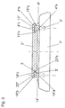
- Fig. 3 shows an embodiment in which the right in the drawing figure, "leading" guide element 4 "in reversal to the embodiment shown in Fig. 1 next to a base part 4" a, a guide part 4 “b and pointing inward to the ski center Guide bar 4 "c, which by a sliding profile 13" of the support or base plate 3 "by means of a likewise U-shaped sliding element 13" b can be overlapped or overlapped .
- On the outside of the guide element 4 " is only a support lug 13" a of the slide 13 "on.
- the cooperating components of support or base plate 3 "and guide element 4" are coordinated so that in a tolerance and play-free guidance of the support or base plate 3 "on the guide element 4" the support or base plate 3 "both in is held vertically and horizontally.
- the guide element 14 "shown on the left in FIG. 3 has, in addition to a base part 14" a, a guide part 14 "b and a guide rail 14" c projecting from this to the center of the ski.
- a U-shaped sliding element 23 “b of a sliding profile 23" of the support or base plate 3 "surrounds the guide rail 14" c and holds the base plate 3 "on the guide element 14" in the vertical direction.
- Columns or exemptions 5, 5 ' permit in the horizontal direction a relative movement between the support or base plate 3 "and the guide element 14".
- the invention is not limited to the illustrated embodiments. So it is particularly possible to realize the invention in other sliding boards, such as snowboards. Concerning the design of the guide elements and the sliding profiles cooperating with these on the binding parts or support or base plates, there are a variety of other ways to vertical in the region of the one guide element of the pair of guide elements, the binding member or the support or base plate and to hold in the horizontal direction and in the region of the second guide element only in the vertical direction and with a certain play in the horizontal direction.
Landscapes
- Fittings On The Vehicle Exterior For Carrying Loads, And Devices For Holding Or Mounting Articles (AREA)
- Vibration Prevention Devices (AREA)
- Basic Packing Technique (AREA)
- Ropes Or Cables (AREA)
Claims (6)
- Système de guidage intégré dans la structure d'une latte de glissage, notamment d'un ski, pour un élément fonctionnel d'une attache, consistant en une paire d'éléments de guidage s'étendant en direction longitudinale du ski et espacés en direction latérale du ski,
caractérisé en ce que, pour un maintien sans jeu en direction horizontale et verticale de l'élément fonctionnel (3, 3', 3"), l'un des éléments de guidage (4, 4', 4"), et l'autre élément de guidage (14, 14', 14") pour un maintien sans jeu de l'élément fonctionnel (3, 3', 3") est uniquement réalisé en direction verticale. - Système de guidage selon la revendication 1, caractérisé en ce que l'élément de guidage (4, 4', 4") maintenant l'élément fonctionnel en direction verticale et horizontale comporte au moins une baguette de guidage (4c, 4'c, 4"c) s'étendant en direction longitudinale du ski, qui peut être enveloppée par un élément coulissant (13b, 13'b, 13"b) notamment en forme de U de l'élément fonctionnel (3, 3").
- Système de guidage selon la revendication 1 ou 2, caractérisé en ce que l'élément fonctionnel est maintenu en direction horizontale sur l'élément de guidage (4) maintenant en direction verticale et horizontale par un embout d'appui (13a).
- Système de guidage selon l'une quelconque des revendications 1 à 3, caractérisé en ce que l'élément de guidage (14, 14', 14") maintenant l'élément fonctionnel uniquement en direction verticale comporte une seule baguette de guidage (14c, 14'c, 14"c) pouvant être enveloppée avec un jeu horizontal par un élément coulissant (23b, 23'b, 23"b).
- Planche glissante, notamment ski, avec un système de guidage disposé sur sa face supérieure, intégré dans la structure du ski, pour un élément fonctionnel d'une attache, consistant en une paire d'éléments de guidage s'étendant en direction longitudinale du ski et espacés en direction latérale du ski,
caractérisée en ce que le système de guidage est réalisé selon au moins l'une quelconque des revendications 1 à 4. - Planche glissante, avec un noyau expansé selon la revendication 5, caractérisée en ce que la paire d'éléments de guidage (4, 4', 4", 14, 14', 14") est ancrée dans la mousse du noyau.
Applications Claiming Priority (2)
| Application Number | Priority Date | Filing Date | Title |
|---|---|---|---|
| AT0162402A AT414100B (de) | 2002-10-28 | 2002-10-28 | In den aufbau eines gleitbrettes, insbesondere eines skis, integrierte führungseinrichtung und gleitbrett, insbesondere ski |
| AT16242002 | 2002-10-28 |
Publications (2)
| Publication Number | Publication Date |
|---|---|
| EP1415687A1 EP1415687A1 (fr) | 2004-05-06 |
| EP1415687B1 true EP1415687B1 (fr) | 2007-05-09 |
Family
ID=32074998
Family Applications (1)
| Application Number | Title | Priority Date | Filing Date |
|---|---|---|---|
| EP03021703A Expired - Lifetime EP1415687B1 (fr) | 2002-10-28 | 2003-09-25 | Système de guidage intégré pour une fixation de ski |
Country Status (3)
| Country | Link |
|---|---|
| EP (1) | EP1415687B1 (fr) |
| AT (2) | AT414100B (fr) |
| DE (1) | DE50307224D1 (fr) |
Families Citing this family (1)
| Publication number | Priority date | Publication date | Assignee | Title |
|---|---|---|---|---|
| DE102004032386A1 (de) * | 2004-07-02 | 2006-01-26 | Völkl Sports GmbH & Co.KG | Schneegleitbrett |
Family Cites Families (14)
| Publication number | Priority date | Publication date | Assignee | Title |
|---|---|---|---|---|
| US3798691A (en) * | 1972-09-13 | 1974-03-26 | Lake Region Prod Inc | Water ski foot binding |
| AT367642B (de) * | 1980-06-12 | 1982-07-26 | Tyrolia Freizeitgeraete | Verstelleinrichtung fuer einen skibindungsteil |
| AT369657B (de) * | 1980-12-19 | 1983-01-25 | Tyrolia Freizeitgeraete | Verstelleinrichtung fuer einen backen |
| AT375260B (de) * | 1980-12-19 | 1984-07-25 | Tyrolia Freizeitgeraete | Vorrichtung zur laengsverstellung von skibindungsteilen |
| AT388877B (de) * | 1987-12-23 | 1989-09-11 | Tyrolia Freizeitgeraete | Sicherheitsskibindung |
| US5348355A (en) * | 1991-12-11 | 1994-09-20 | Mazda Motor Corporation | Automotive engine hood latch mechanism |
| DE4445283A1 (de) * | 1994-12-19 | 1996-06-20 | Emag Masch Vertriebs Serv Gmbh | Werkzeugmaschine |
| FR2766379B1 (fr) * | 1997-07-22 | 1999-10-08 | Rossignol Sa | Plate-forme pour le montage d'une fixation de ski sur un ski |
| JP2000324274A (ja) | 1999-03-10 | 2000-11-24 | Yasuo Muramatsu | 通話料金管理システム |
| FR2809635B1 (fr) * | 2000-05-30 | 2002-08-30 | Salomon Sa | Dispositif interface entre un ski et une chaussure |
| EP1161972B1 (fr) * | 2000-06-09 | 2004-09-22 | Völkl Sports GmbH & Co. KG | Planche de glisse, notamment ski ainsi qu'un système de rails profilés pour une telle planche de glisse |
| EP1188464A1 (fr) * | 2000-09-15 | 2002-03-20 | Reinhard Mag. Kittler | Article de sports d'hiver |
| CH696024A5 (de) * | 2000-12-29 | 2006-11-30 | Atomic Austria Gmbh | Gleitvorrichtung, z.B. Schi, Snowboard. |
| FR2823681B1 (fr) * | 2001-04-24 | 2003-06-13 | Rene Bressand | Dispositif de montage/demontage rapides d'une fixation de ski sur un ski |
-
2002
- 2002-10-28 AT AT0162402A patent/AT414100B/de not_active IP Right Cessation
-
2003
- 2003-09-25 EP EP03021703A patent/EP1415687B1/fr not_active Expired - Lifetime
- 2003-09-25 AT AT03021703T patent/ATE361779T1/de active
- 2003-09-25 DE DE50307224T patent/DE50307224D1/de not_active Expired - Lifetime
Also Published As
| Publication number | Publication date |
|---|---|
| ATA16242002A (de) | 2005-12-15 |
| EP1415687A1 (fr) | 2004-05-06 |
| ATE361779T1 (de) | 2007-06-15 |
| DE50307224D1 (de) | 2007-06-21 |
| AT414100B (de) | 2006-09-15 |
Similar Documents
| Publication | Publication Date | Title |
|---|---|---|
| EP0056484A2 (fr) | Battant de porte ou de fenêtre équipé d'une armature pour barres coulissantes | |
| EP1276658B1 (fr) | Dispositif de coulissement pour sellette d'attelage | |
| EP0440104A1 (fr) | Mur de séparation pour la subdivision d'espaces | |
| DE3943203C2 (de) | Verfahren zum schnellen Montieren einer Bindung für einen Schuh auf einem Ski, insbesondere einer Langlaufskibindung, Ski und Bindung zur Durchführung eines solchen Montageverfahrens | |
| DE2604882C2 (de) | Befahrbare Fläche für mechanische Parkeinrichtungen, Rampen, Hebebühnen o.dgl. | |
| WO2014101995A2 (fr) | Dispositif de recouvrement pour un module flasque de retenue pouvant être amené en accouplement libérable a l'aide d'un module a clavettes de fermeture créant une liaison entre une porte de véhicule et un cadre de paroi latérale sur une carrosserie de véhicule | |
| EP1424107B1 (fr) | Planche de glisse, en particulier un ski | |
| EP0104340A2 (fr) | Agencement, en particulier pour une cloison de douche | |
| DE2757450A1 (de) | Betonschalung | |
| DE9015060U1 (de) | Schubkastenführung | |
| EP0340285A1 (fr) | Tiroir a deux chassis lateraux, de preference metalliques | |
| AT414100B (de) | In den aufbau eines gleitbrettes, insbesondere eines skis, integrierte führungseinrichtung und gleitbrett, insbesondere ski | |
| DE1227629B (de) | Gitterfoermiges Traggerippe, insbesondere fuer eine Haengedecke | |
| DE9215844U1 (de) | Beschlagteileverbindung | |
| DE2159244C3 (de) | Eckumlenkung für Treibstangenbeschläge | |
| DE2800231C3 (de) | Verbundprofilstab eines Rahmens für Fenter, Türen u.dgl. | |
| DE3301326A1 (de) | Verbesserungen bei waermesperren in fenstern, tueren oder anderen rahmenkonstruktionen | |
| AT337426B (de) | Anordnung zum verbinden von plattenelementen | |
| DE9402042U1 (de) | Seitenzarge eines Schubkastens | |
| DE202004017047U1 (de) | Türsystem mit Führungselement | |
| DE2513552A1 (de) | Laufschiene | |
| DE1683309C (de) | Verbindung zweier im Winkel zueinan der angeordneter Profilstabe eines Fenster rahmens, Türrahmens, od dgl | |
| AT7293U1 (de) | Gleitbrett, insbesondere ski | |
| DE7344616U (de) | Stuetzenschalung | |
| DE8322358U1 (de) | Aus kunststoff bestehende gartenbank |
Legal Events
| Date | Code | Title | Description |
|---|---|---|---|
| PUAI | Public reference made under article 153(3) epc to a published international application that has entered the european phase |
Free format text: ORIGINAL CODE: 0009012 |
|
| AK | Designated contracting states |
Kind code of ref document: A1 Designated state(s): AT BE BG CH CY CZ DE DK EE ES FI FR GB GR HU IE IT LI LU MC NL PT RO SE SI SK TR |
|
| AX | Request for extension of the european patent |
Extension state: AL LT LV MK |
|
| 17P | Request for examination filed |
Effective date: 20041028 |
|
| AKX | Designation fees paid |
Designated state(s): AT CH DE FR IT LI |
|
| GRAP | Despatch of communication of intention to grant a patent |
Free format text: ORIGINAL CODE: EPIDOSNIGR1 |
|
| GRAS | Grant fee paid |
Free format text: ORIGINAL CODE: EPIDOSNIGR3 |
|
| GRAA | (expected) grant |
Free format text: ORIGINAL CODE: 0009210 |
|
| AK | Designated contracting states |
Kind code of ref document: B1 Designated state(s): AT CH DE FR IT LI |
|
| REG | Reference to a national code |
Ref country code: CH Ref legal event code: EP |
|
| REF | Corresponds to: |
Ref document number: 50307224 Country of ref document: DE Date of ref document: 20070621 Kind code of ref document: P |
|
| ET | Fr: translation filed | ||
| PLBE | No opposition filed within time limit |
Free format text: ORIGINAL CODE: 0009261 |
|
| STAA | Information on the status of an ep patent application or granted ep patent |
Free format text: STATUS: NO OPPOSITION FILED WITHIN TIME LIMIT |
|
| 26N | No opposition filed |
Effective date: 20080212 |
|
| REG | Reference to a national code |
Ref country code: FR Ref legal event code: PLFP Year of fee payment: 14 |
|
| REG | Reference to a national code |
Ref country code: FR Ref legal event code: PLFP Year of fee payment: 15 |
|
| PGFP | Annual fee paid to national office [announced via postgrant information from national office to epo] |
Ref country code: CH Payment date: 20170921 Year of fee payment: 15 Ref country code: FR Payment date: 20170928 Year of fee payment: 15 Ref country code: IT Payment date: 20170926 Year of fee payment: 15 Ref country code: DE Payment date: 20170928 Year of fee payment: 15 |
|
| PGFP | Annual fee paid to national office [announced via postgrant information from national office to epo] |
Ref country code: AT Payment date: 20170922 Year of fee payment: 15 |
|
| REG | Reference to a national code |
Ref country code: DE Ref legal event code: R119 Ref document number: 50307224 Country of ref document: DE |
|
| REG | Reference to a national code |
Ref country code: CH Ref legal event code: PL |
|
| REG | Reference to a national code |
Ref country code: AT Ref legal event code: MM01 Ref document number: 361779 Country of ref document: AT Kind code of ref document: T Effective date: 20180925 |
|
| PG25 | Lapsed in a contracting state [announced via postgrant information from national office to epo] |
Ref country code: IT Free format text: LAPSE BECAUSE OF NON-PAYMENT OF DUE FEES Effective date: 20180925 Ref country code: DE Free format text: LAPSE BECAUSE OF NON-PAYMENT OF DUE FEES Effective date: 20190402 |
|
| PG25 | Lapsed in a contracting state [announced via postgrant information from national office to epo] |
Ref country code: CH Free format text: LAPSE BECAUSE OF NON-PAYMENT OF DUE FEES Effective date: 20180930 Ref country code: FR Free format text: LAPSE BECAUSE OF NON-PAYMENT OF DUE FEES Effective date: 20180930 Ref country code: LI Free format text: LAPSE BECAUSE OF NON-PAYMENT OF DUE FEES Effective date: 20180930 |
|
| PG25 | Lapsed in a contracting state [announced via postgrant information from national office to epo] |
Ref country code: AT Free format text: LAPSE BECAUSE OF NON-PAYMENT OF DUE FEES Effective date: 20180925 |