EP1415718A2 - Dispositif de revêtement par projection d'un liquide de revêtement - Google Patents
Dispositif de revêtement par projection d'un liquide de revêtement Download PDFInfo
- Publication number
- EP1415718A2 EP1415718A2 EP03019140A EP03019140A EP1415718A2 EP 1415718 A2 EP1415718 A2 EP 1415718A2 EP 03019140 A EP03019140 A EP 03019140A EP 03019140 A EP03019140 A EP 03019140A EP 1415718 A2 EP1415718 A2 EP 1415718A2
- Authority
- EP
- European Patent Office
- Prior art keywords
- valve
- liquid
- compressed gas
- measuring
- valve body
- Prior art date
- Legal status (The legal status is an assumption and is not a legal conclusion. Google has not performed a legal analysis and makes no representation as to the accuracy of the status listed.)
- Granted
Links
- 239000007788 liquid Substances 0.000 title claims abstract description 130
- 239000011248 coating agent Substances 0.000 title claims abstract description 32
- 238000000576 coating method Methods 0.000 title claims abstract description 32
- 238000005507 spraying Methods 0.000 title claims description 25
- 239000007921 spray Substances 0.000 claims description 49
- 230000005534 acoustic noise Effects 0.000 claims description 2
- 239000003570 air Substances 0.000 description 25
- 238000000465 moulding Methods 0.000 description 8
- 230000006835 compression Effects 0.000 description 4
- 238000007906 compression Methods 0.000 description 4
- 238000011144 upstream manufacturing Methods 0.000 description 4
- 230000001419 dependent effect Effects 0.000 description 3
- 239000012530 fluid Substances 0.000 description 3
- 238000005259 measurement Methods 0.000 description 3
- 238000000889 atomisation Methods 0.000 description 2
- 238000009530 blood pressure measurement Methods 0.000 description 2
- 230000007547 defect Effects 0.000 description 2
- 238000007493 shaping process Methods 0.000 description 2
- 230000011664 signaling Effects 0.000 description 2
- 239000012080 ambient air Substances 0.000 description 1
- 238000007600 charging Methods 0.000 description 1
- 238000004891 communication Methods 0.000 description 1
- 238000011109 contamination Methods 0.000 description 1
- 230000001934 delay Effects 0.000 description 1
- 238000001514 detection method Methods 0.000 description 1
- 238000007786 electrostatic charging Methods 0.000 description 1
- 238000004880 explosion Methods 0.000 description 1
- 239000000463 material Substances 0.000 description 1
- 238000000034 method Methods 0.000 description 1
- 230000003287 optical effect Effects 0.000 description 1
- 239000002245 particle Substances 0.000 description 1
- 238000007789 sealing Methods 0.000 description 1
Images

Classifications
-
- B—PERFORMING OPERATIONS; TRANSPORTING
- B05—SPRAYING OR ATOMISING IN GENERAL; APPLYING FLUENT MATERIALS TO SURFACES, IN GENERAL
- B05B—SPRAYING APPARATUS; ATOMISING APPARATUS; NOZZLES
- B05B7/00—Spraying apparatus for discharge of liquids or other fluent materials from two or more sources, e.g. of liquid and air, of powder and gas
- B05B7/02—Spray pistols; Apparatus for discharge
- B05B7/12—Spray pistols; Apparatus for discharge designed to control volume of flow, e.g. with adjustable passages
-
- F—MECHANICAL ENGINEERING; LIGHTING; HEATING; WEAPONS; BLASTING
- F16—ENGINEERING ELEMENTS AND UNITS; GENERAL MEASURES FOR PRODUCING AND MAINTAINING EFFECTIVE FUNCTIONING OF MACHINES OR INSTALLATIONS; THERMAL INSULATION IN GENERAL
- F16K—VALVES; TAPS; COCKS; ACTUATING-FLOATS; DEVICES FOR VENTING OR AERATING
- F16K37/00—Special means in or on valves or other cut-off apparatus for indicating or recording operation thereof, or for enabling an alarm to be given
- F16K37/0066—Hydraulic or pneumatic means
-
- B—PERFORMING OPERATIONS; TRANSPORTING
- B05—SPRAYING OR ATOMISING IN GENERAL; APPLYING FLUENT MATERIALS TO SURFACES, IN GENERAL
- B05B—SPRAYING APPARATUS; ATOMISING APPARATUS; NOZZLES
- B05B7/00—Spraying apparatus for discharge of liquids or other fluent materials from two or more sources, e.g. of liquid and air, of powder and gas
- B05B7/02—Spray pistols; Apparatus for discharge
- B05B7/12—Spray pistols; Apparatus for discharge designed to control volume of flow, e.g. with adjustable passages
- B05B7/1254—Spray pistols; Apparatus for discharge designed to control volume of flow, e.g. with adjustable passages the controlling means being fluid actuated
- B05B7/1263—Spray pistols; Apparatus for discharge designed to control volume of flow, e.g. with adjustable passages the controlling means being fluid actuated pneumatically actuated
- B05B7/1272—Spray pistols; Apparatus for discharge designed to control volume of flow, e.g. with adjustable passages the controlling means being fluid actuated pneumatically actuated actuated by gas involved in spraying, i.e. exiting the nozzle, e.g. as a spraying or jet shaping gas
-
- B—PERFORMING OPERATIONS; TRANSPORTING
- B05—SPRAYING OR ATOMISING IN GENERAL; APPLYING FLUENT MATERIALS TO SURFACES, IN GENERAL
- B05B—SPRAYING APPARATUS; ATOMISING APPARATUS; NOZZLES
- B05B1/00—Nozzles, spray heads or other outlets, with or without auxiliary devices such as valves, heating means
- B05B1/30—Nozzles, spray heads or other outlets, with or without auxiliary devices such as valves, heating means designed to control volume of flow, e.g. with adjustable passages
- B05B1/3033—Nozzles, spray heads or other outlets, with or without auxiliary devices such as valves, heating means designed to control volume of flow, e.g. with adjustable passages the control being effected by relative coaxial longitudinal movement of the controlling element and the spray head
- B05B1/304—Nozzles, spray heads or other outlets, with or without auxiliary devices such as valves, heating means designed to control volume of flow, e.g. with adjustable passages the control being effected by relative coaxial longitudinal movement of the controlling element and the spray head the controlling element being a lift valve
- B05B1/3046—Nozzles, spray heads or other outlets, with or without auxiliary devices such as valves, heating means designed to control volume of flow, e.g. with adjustable passages the control being effected by relative coaxial longitudinal movement of the controlling element and the spray head the controlling element being a lift valve the valve element, e.g. a needle, co-operating with a valve seat located downstream of the valve element and its actuating means, generally in the proximity of the outlet orifice
- B05B1/306—Nozzles, spray heads or other outlets, with or without auxiliary devices such as valves, heating means designed to control volume of flow, e.g. with adjustable passages the control being effected by relative coaxial longitudinal movement of the controlling element and the spray head the controlling element being a lift valve the valve element, e.g. a needle, co-operating with a valve seat located downstream of the valve element and its actuating means, generally in the proximity of the outlet orifice the actuating means being a fluid
Definitions
- the invention relates to a spray coating device for Coating liquid according to the preamble of claim 1.
- the invention relates to a spray coating device for Coating liquid containing a coating liquid spray gun, the a fluid dispensing valve containing a fluid valve seat and one Has liquid valve body, which relative to the liquid valve seat between a liquid valve close position and a liquid valve open position is movable.
- the spray coating device consists of at least one spray gun, which has the features of the invention.
- the invention also relates to a Spray coating device, which in addition to the spray gun also one to it connected control device or at least one connected to it Has sensor.
- a spray gun for coating liquid of this type is from the EP 1 048 359 A2 is known. It is also known from practice to use the spray gun to provide an electromagnetic sensor, which determines whether the Liquid valve body of the liquid dispensing valve in the valve closed position or is in the valve open position. Electromagnetic sensors have that Disadvantage that they are connected to the spray gun and connected via an electrical cable the spray gun can be electrically connected by an electrical connector. This is disadvantageous because the plugs are susceptible to defects, for example one easily bendable little mandrel included as an electrical connector, and that that electrical cable increases the weight of the spray gun and freedom of movement the spray gun.
- Spray guns can be manual spray guns that are held manually, or automatic spray guns, which are held by a carrier and relative to an object can be arranged to be movable or stationary.
- the carrier can be a Be a lifting stand or a robot.
- the spray guns usually have at least one electrode, which for electrostatic charging of the coating liquid at DC high voltage can be connected.
- a spray gun of a comparable type for coating liquid is also from DE 22 09 896 C2 known.
- the spray gun Atomizing air supply which is the atomization of the coating liquid positively influenced, and / or to supply as shaping air, which to that of a Spray nozzle directed liquid to shape the spray, for example, to make a flat spray jet with a round cross section Form spray jet and / or to escape the liquid particles from the to prevent atomized spray.
- the atomizing compressed air and the forming compressed air are already switched on, so that the coating liquid has the required spray quality and Spray form has that for the optimal coating of an object to be coated is necessary, otherwise poor coating qualities will result.
- the objects are automatically turned on Spray guns transported over.
- the Spray guns switched off. So that the objects from the beginning to the end with of sufficient quality must be switched on and off (Opening and closing) the coating liquid and the compressed air for the Atomizing air and / or for the shaping air precisely in time be coordinated. This is done by detecting the position of the Liquid valve body relative to the liquid valve seat Liquid discharge valve in the prior art by electromagnetic Sensors.
- the object is to be achieved Form spray coating device in such a way that it is less prone to defects is and works more precisely with the control of at least one compressed air relative to controlling the dispensing of coating liquid.
- a coating device is thereby characterized in that the spray gun includes a metering valve device, which in a compressed gas measuring valve path and arranged with the liquid valve body common movement is coupled to be actuated by this, wherein the measuring valve device is designed such that it is dependent on the Positions of the liquid valve body in each case then in the compressed gas measuring valve path closing position is when that Liquid dispensing valve is in its fully closed position and when it is in its fully open position, however, then in each case the compressed gas measuring valve path is in the open position when the liquid valve body is in any intermediate position between its full liquid valve open position and its full liquid valve closed position is such that depending on whether compressed gas flows through the measuring valve device or not, it can be automatically determined whether the liquid valve body in one of the two Liquid valve open or liquid valve closed positions or is in any intermediate position.
- the liquid valve body of the liquid discharge valve is preferably one Valve needle.
- the invention provides a detection system through which the real Start position and real end position of the liquid valve body of the Liquid discharge valve is very precisely and reliably measurable. This means you get an exact value when that Liquid dispensing valve of the spray gun is open or closed. Thereby are all runtimes and delays of a spray coating system automatically recognized and need when programming Coating parameters for coating objects no longer to be considered.
- the measuring principle of the invention is based on sound measurement or Air pressure measurement.
- the special mechanism in the spray gun controls you Air pulse that continues until the liquid valve body moves away from it Starting position (valve seat open or valve seat closed position) up to its End position (valve seat closed position or valve seat open position) has moved.
- This Air pulse can be measured by a valve body position sensor by measuring air pressure or measured by sound measurement.
- the valve body position sensor can attached to the spray gun or preferably separated from it and by a hose can be connected to the spray gun.
- the Valve body position sensor is the air pulse by sound measurement or Pressure measurement recorded and for control purposes and / or for signaling purposes used, preferably converted into an electrical signal.
- the electrical The signal is then amplified electronically, and preferably also by a filter made insensitive to ambient air pressures.
- the electrical signal is digitized so that at the output the valve body position sensor an electrical pulse analogous to the duration of the Air pulse arises. This means that for the duration of the movement of the Liquid valve body at the outlet of the valve body position sensor electrical digital signal is measurable, which is then directly through a Control system or can be evaluated for the computer Spray coating operation.
- Such a device and such a method has the advantage that the sensor does not require any electrical lines and contacts, which have to be connected to the spray gun. This will make a big one Operational safety is achieved and there is contamination and risk of explosion locked out.
- the compressed air hose, which the valve body position sensor with the spray gun connects can be housed in a package which also hoses for the compressed air supply to the spray gun for atomizing compressed air and / or forming compressed air and / or coating liquid.
- the valve body position sensor can be designed such that it electrical signal galvanically isolated by an optocoupler.
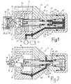
- FIG. 1 and 2 of the drawings show a spray coating device of the invention for coating liquid and contain a Coating liquid spray gun 2, which contains a liquid dispensing valve 4, which has a liquid valve seat 6 and a liquid valve body 8 in shape a valve needle with a conical needle tip 10.
- the Liquid valve body 8 is relative to the liquid valve seat 6 between one complete liquid valve closing position, which is in the lower half of Fig. 2nd and a full liquid valve open position shown in the 2 is linearly movable.
- 1 shows the valve body 8 in any intermediate position between the liquid valve open position and the liquid valve closed position of FIG. 2.
- the liquid valve body 8 is actuated in the closing direction by a Compression spring 12 and in the opening direction against the force of the compression spring 12 Control compressed air in a control compressed air chamber 14 onto a control piston 16, which with the liquid valve body 8 for common linear movement connected is.
- the liquid valve seat 6 is on the back of a nozzle channel 18 Atomizer nozzle 20 formed, which on its back by a Liquid channel 22 supplied coating liquid on the Atomizer nozzle front atomized when the liquid discharge valve 4 opened is.
- Molding gas outlets 26 may be provided for molding pressure gas, which the atomize coating liquid jet of the nozzle channel 18 shapes and for example, is supplied via a compressed gas channel 30.
- one or more atomizer gas outlets 34 may be provided which atomizing gas flow and the atomization of the Coating liquid can support.
- the atomizing compressed gas can over the same compressed gas channel 30 as the molding compressed gas are supplied, or according to another embodiment of the spray gun 2 by a separate one Compressed gas duct 36.
- one or more High voltage electrodes 38 for electrical charging of the Coating liquid can be arranged.
- the spray gun 2 contains a measuring valve device 40 which is shown in FIG a compressed gas measuring valve path 42 and arranged with the liquid valve body 8 is coupled for common axial movement to be actuated by this become.
- a measuring valve device 40 which is shown in FIG a compressed gas measuring valve path 42 and arranged with the liquid valve body 8 is coupled for common axial movement to be actuated by this become.
- too other directions of movement are provided.
- the measuring valve device 40 is dependent on the positions of the Liquid valve body 8 in each case in a compressed gas measuring valve path 42 closing closed position held when the liquid dispensing valve 4 in its full closed position and when it is in its full Open position, both of which are shown in FIG. 2.
- the measuring valve device 40 then moves the compressed gas measuring valve path 42 held open position when the Liquid valve body 8 in any intermediate position, one of which in 1 is shown between its full liquid valve open and its full liquid valve closed position.
- This is dependent of whether compressed gas flows through the measuring valve device 40 or not can be determined automatically whether the liquid valve body 8 in one of the two Full liquid valve open or full positions Liquid valve closed position of Fig. 2 or any in between lying intermediate position, one of which is shown in Fig. 1.
- pressurized gas source for the pressurized gas of the pressurized gas measuring valve path 42 various possibilities.
- One possibility is to use a compressed gas supply separate line to the spray gun.
- the compressed gas for the Compressed gas measuring valve path 42 from one of the compressed gas channels 30 or 36 to branch off which atomizing gas or molding gas or one for contain both-purpose compressed gas.
- 2 is the compressed gas Compressed gas measuring valve path 42 branches off from the compressed gas channel 30, the Compressed gas can be either atomizing compressed gas, molding compressed gas or both can.
- the spray gun 2 is in FIG. 2 compared to FIG. 1 about the longitudinal axis of the Liquid valve body 8 shown rotated. 2 shows one Section 44 of the compressed gas measuring valve path located upstream of the measuring valve device 40 42, and FIG. 1 shows a downstream section 46 of this Compressed gas measuring valve path 42.
- the measuring valve device 40 contains a measuring valve body 48 in one Valve chamber 50, which one at opposite ends of the chamber Compressed gas inlet opening 52 and a compressed gas outlet opening 54, which are designed as valve seats.
- the measuring valve body 48 is of that Liquid valve body 8 linearly movable, alternatively to one or the other to close or open these two valve openings 52 or 54, the one is fully open when the other is fully closed, and vice versa.
- the measuring valve body 48 is preferably provided with two valve elements, e.g. B. Valve seat seals 56 and 58 provided, one of which 56 at the compressed gas inlet valve opening 52 and the other 58 at the compressed gas outlet valve opening 54 each can be applied in a gas-tight manner.
- the measuring valve device 40 thus contains two coupled valves 52/56 and 54/58.
- the compressed gas inlet valve opening 52 and the compressed gas outlet valve opening 54 are on its opening side which can be closed by the measuring valve body 48 by a Compressed gas path 60 connected to one another, which alternatively from measuring valve body 48 by closing the compressed gas inlet valve opening 52 or by closing the Compressed gas outlet valve opening 54 can be closed.
- the measuring valve body 48 is in one Valve chamber 62 arranged and spaced from the valve chamber wall, so that the pressurized gas path 60 between the pressurized gas inlet valve port 52 and the Pressurized gas outlet valve opening 54 by the distance between the Measuring valve body 48 and the chamber wall of the valve chamber 62 is formed.
- the Valve chamber 62 is sealed on both sides by seals 63 and 65, respectively.
- a sensor 66 provided which generates a signal depending on whether compressed gas through the measuring valve device 40 flows through or not. If the compressed gas measuring valve path 42 not from one of the compressed gas channels 30 or 36 for Atomizing compressed gas or molding compressed gas is supplied with compressed gas, but from a pressure gas source independent of this, then the pressure gas sensor 66 in the upstream section 42 or in the downstream section 46, d. H. be arranged upstream or downstream of the measuring valves 48, 50, 52. If on the other hand, as in the embodiment of FIGS.
- Sensor 66 may be attached to spray gun 2, or preferably separate from it and with the downstream section 46 of the compressed gas measuring valve path 42 through a compressed air line 68, preferably a hose, be connected or connectable.
- the sensor 66 generates depending on whether pressurized gas passes through the pressurized gas metering valve 42 flows, a signal, preferably an electrical signal, which for controlling the liquid dispensing valve 4 and / or for signaling purposes for one optical and / or acoustic display of the valve position of the Liquid valve body 8 can serve.
- Sensor 66 is preferably on it Output side connected in terms of signal to a control device 70 for actuation of the liquid valve body 8 by means of control compressed air in the control compressed air chamber 14. This can automatically open and close the Liquid dispensing valve 4 exactly on the positions of objects to be coated can be set, which they have relative to the spray gun 2.
- the sensor 66 can be a pressure sensor which detects the pressure of the compressed gas responds, which flows through the measuring valve device 40. According to In another embodiment, sensor 66 may be a sound sensor that is on acoustic noise of the compressed gas, which is caused by the Measuring valve device 40 flows through.
- the pressurized gas path is between a pressurized gas inlet valve opening 152 and a compressed gas outlet valve opening 154 through one Bypass 160 formed to the valve chamber 162, in which the measuring valve body 148 one Measuring valve device 140 between the compressed gas inlet valve opening 152 and the Compressed gas outlet valve opening 154 is linearly movable.
- the measuring valve body 148 closes the compressed gas inlet valve opening 152 when the liquid valve body 8 completely closes the liquid valve seat 6 and is thus in the Liquid valve closed position.
- the compressed gas outlet valve opening 154 open.
- the measuring valve body 148 closes the Pressurized gas outlet valve opening 154 when the liquid valve body 8 is relative to the liquid valve seat 6 is in a liquid valve open position. in this connection the compressed gas inlet valve opening 152 is open.
- the compressed gas inlet valve opening 152 is only open when it is in the valve state valve chamber 162 through fluid communication with a pressurized gas inlet 153, which is connected to the upstream section 42 of the compressed gas measuring valve path 42 of FIGS. 1 and 2 is connected.
- the compressed gas outlet valve opening 154 has only through valve chamber 162 in its open state Flow connection with a compressed gas outlet 155, which at the downstream portion 46 of the compressed gas sensing valve path 42 of FIGS. 1 and 2 connected.
- the liquid valve body 8 (valve needle) with a pneumatically actuated piston 16 and a compression spring 12 corresponding to FIG. 1 and 2 provided.
- ⁇ are in the measuring valve body one or more holes through which the compressed gas inlet 153 with the Inlet valve opening 152 and / or through which the compressed gas outlet 155 with the Exhaust valve port 154 is connectable rather than through valve chamber 162 therethrough. Furthermore, connections can be made partly through the holes and partly through the Valve chamber to be formed.
- the spray gun of FIG. 3 has the same features as the spray gun 2 of FIG. 1 and 2, insofar as not expressly differences here with reference to FIG. 3 have been described.
- FIG. 4 shows a spray gun 202 with a measuring valve body 248, which in one Valve chamber 262 of a metering valve device 240 from the liquid valve body 8 is linearly movable, with which it is coupled for common movement.
- the measuring valve body 248 is a valve spool, which is on the chamber side wall is airtight. In the chamber side wall are adjacent to each other, for example facing each other, a pressurized gas inlet valve port 252 and one Compressed gas outlet valve opening 254 formed by the measuring valve body 248 alternatively can be connected to one another or can be separated from one another by closing depending on the axial positions of the measuring valve body 248.
- the two Openings 252 and 254 are fluidly separated from one another when the Liquid valve body 8 in the full liquid valve closed position or is in the full liquid valve open position.
- the two openings 252 and However, 254 are fluidly connected to each other through the valve chamber 262, between two sealing the valve chamber 262 and with axial Distance from each other spool 256 and 258 when the Liquid valve body 248 in one between said liquid valve end positions lying intermediate position.
- the measuring valve body 248 forms one Passage through valve chamber 262 between openings 252 and 254. This is also according to another embodiment by one or more Holes in the measuring valve body 248 possible instead of through the valve chamber. Further can these connections partly through such holes and partly through the Valve chamber to be formed.
- the liquid valve body 8 of FIG. 4 is in accordance with FIGS. 1 and 2 a control piston 16 pneumatically and actuated by a compression spring 12, such as this has been described with reference to FIGS. 1 and 2.
- the measuring valve device 240 with the spray gun 202 of FIG. 4 is the same Formed like the embodiment of FIGS. 1 and 2 except for here differences described with reference to FIG. 4.
- the compressed gas can be air or other gas.
Landscapes
- Engineering & Computer Science (AREA)
- General Engineering & Computer Science (AREA)
- Mechanical Engineering (AREA)
- Nozzles (AREA)
- Spray Control Apparatus (AREA)
Applications Claiming Priority (2)
| Application Number | Priority Date | Filing Date | Title |
|---|---|---|---|
| DE10250531 | 2002-10-29 | ||
| DE10250531A DE10250531A1 (de) | 2002-10-29 | 2002-10-29 | Spritzbeschichtungsvorrichtung für Beschichtungsflüssigkeit |
Publications (3)
| Publication Number | Publication Date |
|---|---|
| EP1415718A2 true EP1415718A2 (fr) | 2004-05-06 |
| EP1415718A3 EP1415718A3 (fr) | 2006-01-18 |
| EP1415718B1 EP1415718B1 (fr) | 2008-01-16 |
Family
ID=31984434
Family Applications (1)
| Application Number | Title | Priority Date | Filing Date |
|---|---|---|---|
| EP03019140A Expired - Lifetime EP1415718B1 (fr) | 2002-10-29 | 2003-08-23 | Dispositif de revêtement par projection d'un liquide de revêtement |
Country Status (12)
| Country | Link |
|---|---|
| US (1) | US6955724B2 (fr) |
| EP (1) | EP1415718B1 (fr) |
| JP (1) | JP4387756B2 (fr) |
| KR (1) | KR100523026B1 (fr) |
| CN (1) | CN1253248C (fr) |
| AT (1) | ATE383909T1 (fr) |
| CA (1) | CA2447213C (fr) |
| DE (3) | DE10250531A1 (fr) |
| ES (1) | ES2299652T3 (fr) |
| MX (1) | MXPA03009773A (fr) |
| PT (1) | PT1415718E (fr) |
| TW (1) | TWI238742B (fr) |
Families Citing this family (20)
| Publication number | Priority date | Publication date | Assignee | Title |
|---|---|---|---|---|
| US20060222777A1 (en) * | 2005-04-05 | 2006-10-05 | General Electric Company | Method for applying a plasma sprayed coating using liquid injection |
| US20080011333A1 (en) * | 2006-07-13 | 2008-01-17 | Rodgers Michael C | Cleaning coating dispensers |
| US7926748B2 (en) * | 2008-03-10 | 2011-04-19 | Illinois Tool Works Inc. | Generator for air-powered electrostatically aided coating dispensing device |
| US8496194B2 (en) | 2008-03-10 | 2013-07-30 | Finishing Brands Holdings Inc. | Method and apparatus for retaining highly torqued fittings in molded resin or polymer housing |
| US8590817B2 (en) * | 2008-03-10 | 2013-11-26 | Illinois Tool Works Inc. | Sealed electrical source for air-powered electrostatic atomizing and dispensing device |
| US8016213B2 (en) * | 2008-03-10 | 2011-09-13 | Illinois Tool Works Inc. | Controlling temperature in air-powered electrostatically aided coating material atomizer |
| US7988075B2 (en) | 2008-03-10 | 2011-08-02 | Illinois Tool Works Inc. | Circuit board configuration for air-powered electrostatically aided coating material atomizer |
| USD608858S1 (en) | 2008-03-10 | 2010-01-26 | Illinois Tool Works Inc. | Coating material dispensing device |
| US8770496B2 (en) * | 2008-03-10 | 2014-07-08 | Finishing Brands Holdings Inc. | Circuit for displaying the relative voltage at the output electrode of an electrostatically aided coating material atomizer |
| US7918409B2 (en) * | 2008-04-09 | 2011-04-05 | Illinois Tool Works Inc. | Multiple charging electrode |
| US7950598B2 (en) * | 2008-12-30 | 2011-05-31 | Graco Minnesota Inc. | Integrated flow control assembly for air-assisted spray gun |
| US7971806B2 (en) * | 2008-12-30 | 2011-07-05 | Graco Minnesota Inc. | Poppet check valve for air-assisted spray gun |
| US8225968B2 (en) | 2009-05-12 | 2012-07-24 | Illinois Tool Works Inc. | Seal system for gear pumps |
| DE102009044464A1 (de) * | 2009-11-09 | 2011-05-12 | Walter Westenberger | Spritzpistole |
| US8794547B2 (en) * | 2012-05-15 | 2014-08-05 | Stolle Machinery Company, Llc | Smart solenoid compound gun driver and automatic calibration method |
| DE202012006182U1 (de) * | 2012-06-27 | 2013-07-01 | Harald Adolf Sonnleitner | Zerstäuber zum Zerstäuben eines Beschichtungsmittels |
| JP5946597B1 (ja) * | 2016-04-20 | 2016-07-06 | 新倉工業株式会社 | 噴霧ノズル装置 |
| FR3058331B1 (fr) * | 2016-11-04 | 2023-05-19 | Exel Ind | Ensemble de projection pneumatique, restricteur pour un tel ensemble et installation de projection de produit de revetement comprenant un tel ensemble ou un tel restricteur |
| KR101977370B1 (ko) | 2017-10-20 | 2019-05-10 | 대양테크(주) | 금형과 스폰지를 이용한 이중 코팅장치 |
| JP2023159558A (ja) * | 2022-04-20 | 2023-11-01 | 株式会社リコー | 塗工ノズル及び塗工装置 |
Citations (2)
| Publication number | Priority date | Publication date | Assignee | Title |
|---|---|---|---|---|
| DE2209896C2 (de) | 1971-03-03 | 1986-07-17 | Graco Inc., Minneapolis, Minn. | Zerstäubungsverfahren für niederzuschlagende flüssige Überzugsmaterialien und Vorrichtung zur Durchführung des Zerstäubungsverfahrens |
| EP1048359A2 (fr) | 1999-04-27 | 2000-11-02 | ITW Oberflächentechnik GmbH | Pistolet de pulvérisation pour l'application de revêtements |
Family Cites Families (6)
| Publication number | Priority date | Publication date | Assignee | Title |
|---|---|---|---|---|
| US4922852A (en) * | 1986-10-30 | 1990-05-08 | Nordson Corporation | Apparatus for dispensing fluid materials |
| DE3713999A1 (de) * | 1987-04-27 | 1988-11-10 | Behr Industrieanlagen | Verfahren zum selbsttaetigen serienweisen beschichten von werkstuecken |
| US4944243A (en) * | 1989-06-21 | 1990-07-31 | Taise Corporation | Apparatus for automatically painting external wall of building |
| US5228342A (en) * | 1991-07-26 | 1993-07-20 | Westinghouse Electric Corp. | Ultrasonic position sensor and method |
| US6010740A (en) * | 1997-09-30 | 2000-01-04 | Preferred Machining Corporation | Fluid dispensing system |
| CN1285838C (zh) * | 2001-05-16 | 2006-11-22 | Esec贸易公司 | 压力传感器 |
-
2002
- 2002-10-29 DE DE10250531A patent/DE10250531A1/de not_active Ceased
-
2003
- 2003-08-23 EP EP03019140A patent/EP1415718B1/fr not_active Expired - Lifetime
- 2003-08-23 PT PT03019140T patent/PT1415718E/pt unknown
- 2003-08-23 AT AT03019140T patent/ATE383909T1/de active
- 2003-08-23 DE DE50309010T patent/DE50309010D1/de not_active Expired - Lifetime
- 2003-08-23 ES ES03019140T patent/ES2299652T3/es not_active Expired - Lifetime
- 2003-09-10 TW TW092124955A patent/TWI238742B/zh not_active IP Right Cessation
- 2003-10-14 JP JP2003354008A patent/JP4387756B2/ja not_active Expired - Fee Related
- 2003-10-21 KR KR10-2003-0073284A patent/KR100523026B1/ko not_active Expired - Fee Related
- 2003-10-23 US US10/690,591 patent/US6955724B2/en not_active Expired - Fee Related
- 2003-10-24 MX MXPA03009773A patent/MXPA03009773A/es active IP Right Grant
- 2003-10-28 CA CA2447213A patent/CA2447213C/fr not_active Expired - Fee Related
- 2003-10-29 CN CNB2003101044140A patent/CN1253248C/zh not_active Expired - Fee Related
- 2003-10-29 DE DE20316596U patent/DE20316596U1/de not_active Expired - Lifetime
Patent Citations (2)
| Publication number | Priority date | Publication date | Assignee | Title |
|---|---|---|---|---|
| DE2209896C2 (de) | 1971-03-03 | 1986-07-17 | Graco Inc., Minneapolis, Minn. | Zerstäubungsverfahren für niederzuschlagende flüssige Überzugsmaterialien und Vorrichtung zur Durchführung des Zerstäubungsverfahrens |
| EP1048359A2 (fr) | 1999-04-27 | 2000-11-02 | ITW Oberflächentechnik GmbH | Pistolet de pulvérisation pour l'application de revêtements |
Also Published As
| Publication number | Publication date |
|---|---|
| CN1253248C (zh) | 2006-04-26 |
| DE20316596U1 (de) | 2004-03-04 |
| TW200414935A (en) | 2004-08-16 |
| DE50309010D1 (de) | 2008-03-06 |
| PT1415718E (pt) | 2008-04-07 |
| KR100523026B1 (ko) | 2005-10-24 |
| US20040079284A1 (en) | 2004-04-29 |
| JP4387756B2 (ja) | 2009-12-24 |
| CN1498689A (zh) | 2004-05-26 |
| EP1415718B1 (fr) | 2008-01-16 |
| TWI238742B (en) | 2005-09-01 |
| MXPA03009773A (es) | 2005-09-13 |
| ES2299652T3 (es) | 2008-06-01 |
| KR20040038668A (ko) | 2004-05-08 |
| JP2004148306A (ja) | 2004-05-27 |
| EP1415718A3 (fr) | 2006-01-18 |
| US6955724B2 (en) | 2005-10-18 |
| DE10250531A1 (de) | 2004-05-19 |
| ATE383909T1 (de) | 2008-02-15 |
| CA2447213A1 (fr) | 2004-04-29 |
| CA2447213C (fr) | 2010-05-11 |
Similar Documents
| Publication | Publication Date | Title |
|---|---|---|
| EP1415718B1 (fr) | Dispositif de revêtement par projection d'un liquide de revêtement | |
| DE2217865C3 (de) | Elektrostatische Spruehpistole zum Auftragen von partikelfoermigem Material | |
| EP0979964B1 (fr) | Ensemble de soupapes pour la commande de l'écoulement du matériau dans une installation de revêtement | |
| DE2737680A1 (de) | Spritzpistole | |
| WO2023041655A1 (fr) | Pistolet de pulvérisation et procédé de fonctionnement d'un pistolet de pulvérisation | |
| DE69004441T2 (de) | Modularer Beschichtungsapparat für Dosen. | |
| DE102007049219A1 (de) | Pulverfördervorrichtung für Pulversprühbeschichtungsvorrichtungen | |
| EP0305821B1 (fr) | Dispositif pour fermer l'embranchement d'un tube | |
| EP3113887B1 (fr) | Dispositif d'extension pour appareils de pulvérisation et appareils de pulvérisation | |
| DE2646719C3 (de) | Spritzpistole | |
| DE3644184C2 (fr) | ||
| DE2757522C2 (de) | Rund- oder Ringstrahldüse zum Erzeugen und Abstrahlen eines Nebels oder Aerosols zur Beschichtung von Gegenständen | |
| DE2048043C3 (de) | Sprühvorrichtung | |
| DE2256517B2 (de) | Spritzpistole für viskose Flüssigkeiten | |
| DE102020115174A1 (de) | Spritzpistole, insbesondere Farbspritzpistole | |
| DE202015004222U1 (de) | Luftmengenreguliereinrichtung, Blaspistole, Trockenblasvorrichtung und Spritzpistole, insbesondere Farbspritzpistole | |
| DE10212601A1 (de) | Zerstäuber für eine Beschichtungsanlage | |
| DE19503413C2 (de) | Vorrichtung zum Einbringen von Schüttgut in eine Förderleitung | |
| EP1314480A1 (fr) | Procédé et appareil pour un système d'alimentation en peinture dans un appareil de revêtement avec un ramoneur | |
| CH673786A5 (fr) | ||
| DE2626612A1 (de) | Traenkvorrichtung bzw. -ventil fuer vieh | |
| EP1384518B1 (fr) | Procédé ainsi qu'ensemble de valves pour commander le changement de couleur dans une installation de revêtement | |
| DE3011359C2 (de) | Zerstäuber mit elektromagnetischem Nadelantrieb | |
| DE4104937A1 (de) | Fluessigkeitssensor | |
| DE2430814A1 (de) | Verfahren zum auftragen von ueberzuegen und auskleidungen in engen raeumen und spritzpistolen zur ausfuehrung des verfahrens |
Legal Events
| Date | Code | Title | Description |
|---|---|---|---|
| PUAI | Public reference made under article 153(3) epc to a published international application that has entered the european phase |
Free format text: ORIGINAL CODE: 0009012 |
|
| AK | Designated contracting states |
Kind code of ref document: A2 Designated state(s): AT BE BG CH CY CZ DE DK EE ES FI FR GB GR HU IE IT LI LU MC NL PT RO SE SI SK TR |
|
| AX | Request for extension of the european patent |
Extension state: AL LT LV MK |
|
| PUAL | Search report despatched |
Free format text: ORIGINAL CODE: 0009013 |
|
| AK | Designated contracting states |
Kind code of ref document: A3 Designated state(s): AT BE BG CH CY CZ DE DK EE ES FI FR GB GR HU IE IT LI LU MC NL PT RO SE SI SK TR |
|
| AX | Request for extension of the european patent |
Extension state: AL LT LV MK |
|
| RIC1 | Information provided on ipc code assigned before grant |
Ipc: B05B 7/12 20060101ALI20051201BHEP Ipc: B05B 1/30 20060101AFI20040217BHEP Ipc: F16K 37/00 20060101ALI20051201BHEP |
|
| 17P | Request for examination filed |
Effective date: 20060520 |
|
| AKX | Designation fees paid |
Designated state(s): AT BE BG CH CY CZ DE DK EE ES FI FR GB GR HU IE IT LI LU MC NL PT RO SE SI SK TR |
|
| GRAP | Despatch of communication of intention to grant a patent |
Free format text: ORIGINAL CODE: EPIDOSNIGR1 |
|
| GRAS | Grant fee paid |
Free format text: ORIGINAL CODE: EPIDOSNIGR3 |
|
| GRAA | (expected) grant |
Free format text: ORIGINAL CODE: 0009210 |
|
| AK | Designated contracting states |
Kind code of ref document: B1 Designated state(s): AT BE BG CH CY CZ DE DK EE ES FI FR GB GR HU IE IT LI LU MC NL PT RO SE SI SK TR |
|
| REG | Reference to a national code |
Ref country code: GB Ref legal event code: FG4D Free format text: NOT ENGLISH |
|
| REG | Reference to a national code |
Ref country code: CH Ref legal event code: EP |
|
| REG | Reference to a national code |
Ref country code: IE Ref legal event code: FG4D Free format text: LANGUAGE OF EP DOCUMENT: GERMAN |
|
| REF | Corresponds to: |
Ref document number: 50309010 Country of ref document: DE Date of ref document: 20080306 Kind code of ref document: P |
|
| REG | Reference to a national code |
Ref country code: PT Ref legal event code: SC4A Free format text: AVAILABILITY OF NATIONAL TRANSLATION Effective date: 20080326 |
|
| GBT | Gb: translation of ep patent filed (gb section 77(6)(a)/1977) |
Effective date: 20080413 |
|
| REG | Reference to a national code |
Ref country code: ES Ref legal event code: FG2A Ref document number: 2299652 Country of ref document: ES Kind code of ref document: T3 |
|
| PG25 | Lapsed in a contracting state [announced via postgrant information from national office to epo] |
Ref country code: FI Free format text: LAPSE BECAUSE OF FAILURE TO SUBMIT A TRANSLATION OF THE DESCRIPTION OR TO PAY THE FEE WITHIN THE PRESCRIBED TIME-LIMIT Effective date: 20080116 |
|
| PG25 | Lapsed in a contracting state [announced via postgrant information from national office to epo] |
Ref country code: BG Free format text: LAPSE BECAUSE OF FAILURE TO SUBMIT A TRANSLATION OF THE DESCRIPTION OR TO PAY THE FEE WITHIN THE PRESCRIBED TIME-LIMIT Effective date: 20080416 |
|
| ET | Fr: translation filed | ||
| PG25 | Lapsed in a contracting state [announced via postgrant information from national office to epo] |
Ref country code: SI Free format text: LAPSE BECAUSE OF FAILURE TO SUBMIT A TRANSLATION OF THE DESCRIPTION OR TO PAY THE FEE WITHIN THE PRESCRIBED TIME-LIMIT Effective date: 20080116 |
|
| REG | Reference to a national code |
Ref country code: IE Ref legal event code: FD4D |
|
| PG25 | Lapsed in a contracting state [announced via postgrant information from national office to epo] |
Ref country code: CZ Free format text: LAPSE BECAUSE OF FAILURE TO SUBMIT A TRANSLATION OF THE DESCRIPTION OR TO PAY THE FEE WITHIN THE PRESCRIBED TIME-LIMIT Effective date: 20080116 Ref country code: IE Free format text: LAPSE BECAUSE OF FAILURE TO SUBMIT A TRANSLATION OF THE DESCRIPTION OR TO PAY THE FEE WITHIN THE PRESCRIBED TIME-LIMIT Effective date: 20080116 Ref country code: DK Free format text: LAPSE BECAUSE OF FAILURE TO SUBMIT A TRANSLATION OF THE DESCRIPTION OR TO PAY THE FEE WITHIN THE PRESCRIBED TIME-LIMIT Effective date: 20080116 Ref country code: SK Free format text: LAPSE BECAUSE OF FAILURE TO SUBMIT A TRANSLATION OF THE DESCRIPTION OR TO PAY THE FEE WITHIN THE PRESCRIBED TIME-LIMIT Effective date: 20080116 Ref country code: SE Free format text: LAPSE BECAUSE OF FAILURE TO SUBMIT A TRANSLATION OF THE DESCRIPTION OR TO PAY THE FEE WITHIN THE PRESCRIBED TIME-LIMIT Effective date: 20080416 |
|
| PLBE | No opposition filed within time limit |
Free format text: ORIGINAL CODE: 0009261 |
|
| STAA | Information on the status of an ep patent application or granted ep patent |
Free format text: STATUS: NO OPPOSITION FILED WITHIN TIME LIMIT |
|
| PG25 | Lapsed in a contracting state [announced via postgrant information from national office to epo] |
Ref country code: RO Free format text: LAPSE BECAUSE OF FAILURE TO SUBMIT A TRANSLATION OF THE DESCRIPTION OR TO PAY THE FEE WITHIN THE PRESCRIBED TIME-LIMIT Effective date: 20080116 |
|
| 26N | No opposition filed |
Effective date: 20081017 |
|
| PG25 | Lapsed in a contracting state [announced via postgrant information from national office to epo] |
Ref country code: MC Free format text: LAPSE BECAUSE OF NON-PAYMENT OF DUE FEES Effective date: 20080831 |
|
| REG | Reference to a national code |
Ref country code: CH Ref legal event code: PL |
|
| GBPC | Gb: european patent ceased through non-payment of renewal fee |
Effective date: 20080823 |
|
| PG25 | Lapsed in a contracting state [announced via postgrant information from national office to epo] |
Ref country code: EE Free format text: LAPSE BECAUSE OF FAILURE TO SUBMIT A TRANSLATION OF THE DESCRIPTION OR TO PAY THE FEE WITHIN THE PRESCRIBED TIME-LIMIT Effective date: 20080116 |
|
| PG25 | Lapsed in a contracting state [announced via postgrant information from national office to epo] |
Ref country code: LI Free format text: LAPSE BECAUSE OF NON-PAYMENT OF DUE FEES Effective date: 20080831 Ref country code: CH Free format text: LAPSE BECAUSE OF NON-PAYMENT OF DUE FEES Effective date: 20080831 |
|
| PG25 | Lapsed in a contracting state [announced via postgrant information from national office to epo] |
Ref country code: CY Free format text: LAPSE BECAUSE OF FAILURE TO SUBMIT A TRANSLATION OF THE DESCRIPTION OR TO PAY THE FEE WITHIN THE PRESCRIBED TIME-LIMIT Effective date: 20080116 |
|
| PG25 | Lapsed in a contracting state [announced via postgrant information from national office to epo] |
Ref country code: GB Free format text: LAPSE BECAUSE OF NON-PAYMENT OF DUE FEES Effective date: 20080823 |
|
| PG25 | Lapsed in a contracting state [announced via postgrant information from national office to epo] |
Ref country code: HU Free format text: LAPSE BECAUSE OF FAILURE TO SUBMIT A TRANSLATION OF THE DESCRIPTION OR TO PAY THE FEE WITHIN THE PRESCRIBED TIME-LIMIT Effective date: 20080717 Ref country code: LU Free format text: LAPSE BECAUSE OF NON-PAYMENT OF DUE FEES Effective date: 20080823 |
|
| PG25 | Lapsed in a contracting state [announced via postgrant information from national office to epo] |
Ref country code: TR Free format text: LAPSE BECAUSE OF FAILURE TO SUBMIT A TRANSLATION OF THE DESCRIPTION OR TO PAY THE FEE WITHIN THE PRESCRIBED TIME-LIMIT Effective date: 20080116 |
|
| PG25 | Lapsed in a contracting state [announced via postgrant information from national office to epo] |
Ref country code: GR Free format text: LAPSE BECAUSE OF FAILURE TO SUBMIT A TRANSLATION OF THE DESCRIPTION OR TO PAY THE FEE WITHIN THE PRESCRIBED TIME-LIMIT Effective date: 20080417 |
|
| PGFP | Annual fee paid to national office [announced via postgrant information from national office to epo] |
Ref country code: PT Payment date: 20110804 Year of fee payment: 9 Ref country code: AT Payment date: 20110731 Year of fee payment: 9 |
|
| PGFP | Annual fee paid to national office [announced via postgrant information from national office to epo] |
Ref country code: NL Payment date: 20110901 Year of fee payment: 9 Ref country code: BE Payment date: 20110825 Year of fee payment: 9 |
|
| BERE | Be: lapsed |
Owner name: ITW OBERFLACHENTECHNIK G.M.B.H. & CO.KG Effective date: 20120831 |
|
| REG | Reference to a national code |
Ref country code: PT Ref legal event code: MM4A Free format text: LAPSE DUE TO NON-PAYMENT OF FEES Effective date: 20130225 |
|
| REG | Reference to a national code |
Ref country code: NL Ref legal event code: V1 Effective date: 20130301 |
|
| REG | Reference to a national code |
Ref country code: AT Ref legal event code: MM01 Ref document number: 383909 Country of ref document: AT Kind code of ref document: T Effective date: 20120823 |
|
| PG25 | Lapsed in a contracting state [announced via postgrant information from national office to epo] |
Ref country code: NL Free format text: LAPSE BECAUSE OF NON-PAYMENT OF DUE FEES Effective date: 20130301 |
|
| PG25 | Lapsed in a contracting state [announced via postgrant information from national office to epo] |
Ref country code: PT Free format text: LAPSE BECAUSE OF NON-PAYMENT OF DUE FEES Effective date: 20130225 Ref country code: BE Free format text: LAPSE BECAUSE OF NON-PAYMENT OF DUE FEES Effective date: 20120831 |
|
| PG25 | Lapsed in a contracting state [announced via postgrant information from national office to epo] |
Ref country code: AT Free format text: LAPSE BECAUSE OF NON-PAYMENT OF DUE FEES Effective date: 20120823 |
|
| REG | Reference to a national code |
Ref country code: DE Ref legal event code: R081 Ref document number: 50309010 Country of ref document: DE Owner name: FINISHING BRANDS GERMANY GMBH, DE Free format text: FORMER OWNER: ITW OBERFLAECHENTECHNIK GMBH, 63128 DIETZENBACH, DE Effective date: 20140306 |
|
| REG | Reference to a national code |
Ref country code: FR Ref legal event code: CD Owner name: FINISHING BRANDS GERMANY GMBH Effective date: 20140326 |
|
| REG | Reference to a national code |
Ref country code: ES Ref legal event code: PC2A Owner name: FINISHING BRANDAS GERMANY GMBH Effective date: 20150811 Ref country code: ES Ref legal event code: PC2A Owner name: FINISHING BRANDS GERMANY GMBH Effective date: 20151005 Ref country code: FR Ref legal event code: PLFP Year of fee payment: 13 |
|
| REG | Reference to a national code |
Ref country code: FR Ref legal event code: PLFP Year of fee payment: 14 |
|
| PGFP | Annual fee paid to national office [announced via postgrant information from national office to epo] |
Ref country code: IT Payment date: 20160824 Year of fee payment: 14 Ref country code: DE Payment date: 20160826 Year of fee payment: 14 |
|
| PGFP | Annual fee paid to national office [announced via postgrant information from national office to epo] |
Ref country code: FR Payment date: 20160825 Year of fee payment: 14 |
|
| PGFP | Annual fee paid to national office [announced via postgrant information from national office to epo] |
Ref country code: ES Payment date: 20160826 Year of fee payment: 14 |
|
| REG | Reference to a national code |
Ref country code: DE Ref legal event code: R119 Ref document number: 50309010 Country of ref document: DE |
|
| REG | Reference to a national code |
Ref country code: FR Ref legal event code: ST Effective date: 20180430 |
|
| PG25 | Lapsed in a contracting state [announced via postgrant information from national office to epo] |
Ref country code: DE Free format text: LAPSE BECAUSE OF NON-PAYMENT OF DUE FEES Effective date: 20180301 |
|
| PG25 | Lapsed in a contracting state [announced via postgrant information from national office to epo] |
Ref country code: IT Free format text: LAPSE BECAUSE OF NON-PAYMENT OF DUE FEES Effective date: 20170823 Ref country code: FR Free format text: LAPSE BECAUSE OF NON-PAYMENT OF DUE FEES Effective date: 20170831 |
|
| REG | Reference to a national code |
Ref country code: ES Ref legal event code: FD2A Effective date: 20181024 |
|
| REG | Reference to a national code |
Ref country code: ES Ref legal event code: FD2A Effective date: 20181025 |
|
| PG25 | Lapsed in a contracting state [announced via postgrant information from national office to epo] |
Ref country code: ES Free format text: LAPSE BECAUSE OF NON-PAYMENT OF DUE FEES Effective date: 20170824 |