EP1415746A2 - Outil motorisé - Google Patents
Outil motorisé Download PDFInfo
- Publication number
- EP1415746A2 EP1415746A2 EP03025019A EP03025019A EP1415746A2 EP 1415746 A2 EP1415746 A2 EP 1415746A2 EP 03025019 A EP03025019 A EP 03025019A EP 03025019 A EP03025019 A EP 03025019A EP 1415746 A2 EP1415746 A2 EP 1415746A2
- Authority
- EP
- European Patent Office
- Prior art keywords
- cooling air
- power tool
- work area
- tool bit
- workpiece
- Prior art date
- Legal status (The legal status is an assumption and is not a legal conclusion. Google has not performed a legal analysis and makes no representation as to the accuracy of the status listed.)
- Granted
Links
Images

Classifications
-
- B—PERFORMING OPERATIONS; TRANSPORTING
- B23—MACHINE TOOLS; METAL-WORKING NOT OTHERWISE PROVIDED FOR
- B23D—PLANING; SLOTTING; SHEARING; BROACHING; SAWING; FILING; SCRAPING; LIKE OPERATIONS FOR WORKING METAL BY REMOVING MATERIAL, NOT OTHERWISE PROVIDED FOR
- B23D59/00—Accessories specially designed for sawing machines or sawing devices
- B23D59/006—Accessories specially designed for sawing machines or sawing devices for removing or collecting chips
- B23D59/0062—Accessories specially designed for sawing machines or sawing devices for removing or collecting chips by blowing
-
- B—PERFORMING OPERATIONS; TRANSPORTING
- B23—MACHINE TOOLS; METAL-WORKING NOT OTHERWISE PROVIDED FOR
- B23D—PLANING; SLOTTING; SHEARING; BROACHING; SAWING; FILING; SCRAPING; LIKE OPERATIONS FOR WORKING METAL BY REMOVING MATERIAL, NOT OTHERWISE PROVIDED FOR
- B23D59/00—Accessories specially designed for sawing machines or sawing devices
-
- B—PERFORMING OPERATIONS; TRANSPORTING
- B23—MACHINE TOOLS; METAL-WORKING NOT OTHERWISE PROVIDED FOR
- B23Q—DETAILS, COMPONENTS, OR ACCESSORIES FOR MACHINE TOOLS, e.g. ARRANGEMENTS FOR COPYING OR CONTROLLING; MACHINE TOOLS IN GENERAL CHARACTERISED BY THE CONSTRUCTION OF PARTICULAR DETAILS OR COMPONENTS; COMBINATIONS OR ASSOCIATIONS OF METAL-WORKING MACHINES, NOT DIRECTED TO A PARTICULAR RESULT
- B23Q11/00—Accessories fitted to machine tools for keeping tools or parts of the machine in good working condition or for cooling work; Safety devices specially combined with or arranged in, or specially adapted for use in connection with, machine tools
- B23Q11/0042—Devices for removing chips
- B23Q11/005—Devices for removing chips by blowing
-
- B—PERFORMING OPERATIONS; TRANSPORTING
- B23—MACHINE TOOLS; METAL-WORKING NOT OTHERWISE PROVIDED FOR
- B23Q—DETAILS, COMPONENTS, OR ACCESSORIES FOR MACHINE TOOLS, e.g. ARRANGEMENTS FOR COPYING OR CONTROLLING; MACHINE TOOLS IN GENERAL CHARACTERISED BY THE CONSTRUCTION OF PARTICULAR DETAILS OR COMPONENTS; COMBINATIONS OR ASSOCIATIONS OF METAL-WORKING MACHINES, NOT DIRECTED TO A PARTICULAR RESULT
- B23Q17/00—Arrangements for observing, indicating or measuring on machine tools
- B23Q17/24—Arrangements for observing, indicating or measuring on machine tools using optics or electromagnetic waves
- B23Q17/2404—Arrangements for improving direct observation of the working space, e.g. using mirrors or lamps
-
- Y—GENERAL TAGGING OF NEW TECHNOLOGICAL DEVELOPMENTS; GENERAL TAGGING OF CROSS-SECTIONAL TECHNOLOGIES SPANNING OVER SEVERAL SECTIONS OF THE IPC; TECHNICAL SUBJECTS COVERED BY FORMER USPC CROSS-REFERENCE ART COLLECTIONS [XRACs] AND DIGESTS
- Y10—TECHNICAL SUBJECTS COVERED BY FORMER USPC
- Y10T—TECHNICAL SUBJECTS COVERED BY FORMER US CLASSIFICATION
- Y10T83/00—Cutting
- Y10T83/04—Processes
Definitions
- the present invention relates to a power tool and more particularly, to a technique for effectively utilizing cooling air of a drive motor within a power tool.
- Japanese non-examined and laid-open patent publication No. 8-336803 discloses a technique of cooling the drive motor for driving a tool bit within a power tool. According to this technique, cooling air is introduced into a motor housing by rotating a fan blade so as to cool the drive motor. Then, the cooling air is led into the blade case through a partition structure that defines a cooling air passage between the motor housing and the blade case. According to this technique, the partition structure is designed and configured to improve the motor cooling efficiency.
- an object of the present invention to provide a technique for making the effective use of cooling air for a motor within a power tool in order to rationalize the structure of the power tool.
- representative power tool may comprise a tool bit case, a tool bit, a drive motor and a cooling air guiding member.
- the tool bit is provided within the tool bit case and performs a predetermined operation on a workpiece.
- the drive motor drives the tool bit.
- the cooling air guiding member guides cooling air for cooling the drive motor to a work area of the workpiece to be worked on with the tool bit, when the cooling air is discharged into the tool bit case.
- a representative power tool may include a tool bit that is housed in a tool bit case, a drive motor and a cooling air guiding member.
- the tool bit performs a predetermined operation on a workpiece.
- the "tool bit that performs a predetermined operation on a workpiece” may embrace various tool bits, such as rotary tool bits and reciprocating tool bits.
- the tool bit may comprise a circular saw or other similar power tool in which any obstacles such as cutting-chips are continuously generated during the operation onto the workpiece.
- the drive motor drives the tool bit.
- the drive motor generates heat when driving the tool bit. Therefore, cooling air is supplied to cool the drive motor.
- the cooling air guiding member may guide cooling air to a work area of the workpiece to be worked on with the tool bit, when the cooling air for cooling the drive motor is discharged into the tool bit case. Therefore, cooling air that has been introduced into the power tool in order to cool the drive motor is further led to the work area of the tool bit as being discharged into the tool bit case. As a result, cutting chips and any other obstacles produced during the operation of the power tool can be blown away from the work area, thereby ensuring the visibility of the work area on and around the workpiece, where ink lines or other marks are provided on the workpiece.
- cooling air for cooling the drive motor, which has been led into the power tool can also serve to clean the work area of the power tool.
- the power tool can have rationalized structure. Further, according to the present teachings, quietness of the power tool can be improved owing to the structure in which cooling air is guided to the work area as being discharged into the blade case.
- the term of "guiding the cooling air” may typically embrace the situation that the flowing direction of the cooling air may be changed so as to be led to the work area.
- the flowing direction of the cooling air can be smoothly changed by discharging the cooling air to the tool bit through openings.
- part of the cooling air that has been discharged to the tool bit may be forcibly directed toward the tool bit via an air flow direction change plate or the like that is disposed transversely with respect to the flow of the cooling air.
- the present invention may be preferably applied particularly to a circular saw that is utilized to cut a workpiece with a rotating blade. That is because chips or other obstacles may tend to stay in the work area during the operation of the circular saw.
- the cooling air guiding member may preferably guide the cooling air in a direction transverse to the cutting direction in which the workpiece is cut by the rotating blade.
- the cooling air guiding member of the power tool may include a plate element that is provided in a cooling air discharge port facing the tool bit from the side of a motor housing that houses the drive motor.
- openings may be formed through the plate element obliquely toward the work area so as to guide the cooling air toward the work area.
- the plate element may be integrally formed with the cooling air discharge port Alternatively, the plate element may preferably be formed separately and then mounted onto the discharge port. Further, in the latter case, the plate element may be removably mounted on the discharge port. In view of the efficiency in guiding the cooling air, a plurality of openings may be formed through the plate element obliquely toward the work area.
- the power tool may further include an illuminating member that illuminates the work area of the workpiece.
- the cooling air guiding member may be configured also to serve as a retaining member that retains the illuminating member on the body of the power tool.
- the cooling air guiding member can provide two different functional elements for guiding the cooling air and for retaining the illuminating member. Therefore, the structure of the power tool can be rationalized.
- the retaining member can retain part or all of the components on the body, which components forms the illuminating member, such as the illuminating element, lead wire to the illuminating element, illumination switch and electric substrate.
- the term "illuminating the work area" embraces illumination not only on the work spot itself to be worked on with a tool bit, but on a region near the work spot where ink lines are provided on the work piece.
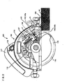
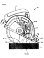
- FIGS. 1 and 2 show a circular saw 101 according to the representative embodiment.
- the circular saw 101 may generally include a body 103 and a base 105 that is connected to the body 103. In use, the base 105 is placed on a workpiece W.
- the body 103 may comprise a motor housing 111 and a blade case 113 which are connected to each other. Grip 117 is integrally formed with the motor housing 111.
- Motor housing 111 houses a drive motor 121 and a cooling fan 131. Cooling fan 131 is fitted around a drive shaft 123 of the drive motor 121. The cooling fan 131 is rotated together with the drive shaft 123 when the drive motor 121 is operated.
- Safety cover 115 is retractably attached to the blade case 113 in such a manner that it extends in the lower region of the blade case 113.
- the blade case 113 houses a blade 129.
- a gear housing 114 is integrally formed with the blade case 113 and extends toward the side of the motor housing 111.
- the gear housing 114 houses a gear 125 and a spindle 127 which are arranged in a position corresponding to the shaft end of the drive shaft 123 extending into the gear housing 114.
- Blade 129 is attached to the shaft end of the spindle 127 in such a manner that it can rotate together with the spindle 127.
- the gear 125 is fitted around the other end of the spindle 127 and engages with the shaft end of the drive shaft 123 of the drive motor 121. With this arrangement, the rotational movement of the drive motor 121 is transmitted to the spindle 127 as being suitably decelerated by the gear 125, so that the blade 129 is rotated around the spindle 127 to thereby cut the workpiece W.
- a cooling air passage 133 extends from inside the motor housing 111 in the boundary region between the motor housing 111 and the blade case 113 (gear housing 114). One end of the cooling air passage 133 forms a cooling air discharge port 135 that faces the blade 129 disposed in the blade case 113.
- a plate element 137 is provided within the cooling air discharge port 135. Plate element 137, together with cooling air guiding slits 139 which will be described below corresponds to the feature of "cooling air guiding member" according to the present invention.
- an illuminating member 141 is provided in the boundary region of the gear housing 114 of the blade case 113.
- the illuminating member 141 includes an LED 143 and a lead wire 145 for the LED 143.
- LED 143 comprises an LED 143a that illuminates a cutting work area G of the workpiece W to be cut by the blade 129 and an LED 143b that illuminates a cutting work area H (see FIG. 5) for enabling plunge cut by the circular saw 101 as described below. The plunge cutting will be explained below in detail.
- Each LED 143 is illuminated as appropriate by operating an illumination switch 119 provided on the grip 117.
- the lead wire connected to each LED 143 is retained on the gear housing 114 in such a manner that it is hidden behind the plate element 127 as shown in FIG. 2.
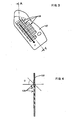
- FIGS. 3 and 4 show a detailed construction of the plate element 137.
- FIG. 3 is a front view of the plate element 137 as viewed from the side of the blade case.
- FIG. 4 is a sectional view taken along line A-A in FIG. 3.
- a plurality of cooling air guiding slits 139 are formed in the plate element 137.
- Each of the cooling air guiding slits 139 is a feature that corresponds to the "opening" according to the present teachings.
- the slit 139 is formed through the plate element 137 at a predetermined inclination angle D with respect to the horizontal plane.
- the cooling air guiding slits 139 are thus configured and arranged to change the direction of the flow of cooling air, which has been introduced from the direction perpendicular to the surface of the plate element 139, to the guiding direction F (see FIGS. 1 and 2 as well as FIG. 4).
- the cooling fan 131 that is fitted around the drive shaft 123 rotates together with the drive shaft 123 (see FIG. 1).
- air around the circular saw 101 is led into the motor housing 111 as cooling air and serves to cool the drive motor 121.
- the cooling air that has been introduced into the motor housing 111 passes through the cooling air passage 133 and the cooling air discharge port 135 and is then discharged toward the blade 129 within the blade case 113.
- the cooling air for the drive motor 121 is thus discharged from inside the motor housing 111 toward the blade 129 through the cooling air discharge port 135. At this time, the cooling air is led in the guiding direction F through the cooling air guiding slits 139 (see FIGS. 3 and 4) that are formed obliquely through the plate element 137. Thus, the cooling air is smoothly guided toward the cutting work area G (see FIG. 2) and removes obstacles in the cutting work area G, such as chips. As shown in FIG. 1, the cooling air is guided toward the axis of rotation of the blade 129, or in the direction transverse to the direction in which the workpiece W is cut with the blade 129 (leftward of the blade 129 as viewed in FIG. 1).
- the cooling air that has been used for cooling the drive motor 121 can be effectively used for removing obstacles, such as chips, in the cutting work area G.
- the LED 143 that defines the illuminating member 141 is positioned so as to face forward within the passage of the cooling air in the guiding direction F. Therefore, when cooling air is guided via the plate element 137 toward the cutting work area G for the blade 129, chips or other obstacles near the LED 143 (LED 143a and LED 143b) can be blown off. Thus, removal of chips or other obstacles in the cutting work area G and provision of visibility by the illuminating member 141 can be attained at the same time.
- the plate element 137 is configured to serve as a supporting plate as well for retaining the lead wire 145 of the illuminating member 141 on the gear housing 114.
- cutting operation using the circular saw 101 is generally started from the end region of the workpiece W by the blade 129 of the circular saw 101 which is set on the end region.
- cutting operation by the blade 129 may not be started from the end region but from the central region of the workpiece as shown in FIG. 5.
- Such cutting operation is generally referred to as "plunge cutting".
- LED 143b within the LEDs 143 of the illuminating member 141 is arranged to illuminate a plunge cutting work area H during plunge cutting operation in which the blade 129 is set on the plunge cutting work area H. Further, the LED 143b is positioned facing forward within the passage in the guiding direction F in which the cooling air is guided via the cooling air guiding slits 139. Therefore, chips or other obstacles can be effectively prevented from being left unremoved near the LED 143b and thus impairing the illuminating capability of the LED 143b.
Landscapes
- Engineering & Computer Science (AREA)
- Mechanical Engineering (AREA)
- Physics & Mathematics (AREA)
- Optics & Photonics (AREA)
- Sawing (AREA)
- Portable Power Tools In General (AREA)
- Motor Or Generator Cooling System (AREA)
Applications Claiming Priority (2)
| Application Number | Priority Date | Filing Date | Title |
|---|---|---|---|
| JP2002320246A JP4656806B2 (ja) | 2002-11-01 | 2002-11-01 | 電動工具 |
| JP2002320246 | 2002-11-01 |
Publications (3)
| Publication Number | Publication Date |
|---|---|
| EP1415746A2 true EP1415746A2 (fr) | 2004-05-06 |
| EP1415746A3 EP1415746A3 (fr) | 2004-10-06 |
| EP1415746B1 EP1415746B1 (fr) | 2007-04-11 |
Family
ID=32089622
Family Applications (1)
| Application Number | Title | Priority Date | Filing Date |
|---|---|---|---|
| EP20030025019 Expired - Lifetime EP1415746B1 (fr) | 2002-11-01 | 2003-10-30 | Outil motorisé |
Country Status (5)
| Country | Link |
|---|---|
| US (1) | US6981779B2 (fr) |
| EP (1) | EP1415746B1 (fr) |
| JP (1) | JP4656806B2 (fr) |
| CN (1) | CN100493835C (fr) |
| DE (1) | DE60313103T2 (fr) |
Cited By (3)
| Publication number | Priority date | Publication date | Assignee | Title |
|---|---|---|---|---|
| WO2009031710A1 (fr) * | 2007-09-07 | 2009-03-12 | Hitachi Koki Co., Ltd. | Outil de coupe portable |
| DE102007057531A1 (de) * | 2007-11-29 | 2009-06-04 | Mafell Ag | Elektrowerkzeug |
| EP2813310A1 (fr) * | 2013-06-13 | 2014-12-17 | Black & Decker Inc. | Scie avec carter de ventilateur |
Families Citing this family (34)
| Publication number | Priority date | Publication date | Assignee | Title |
|---|---|---|---|---|
| US7103979B2 (en) * | 2001-04-20 | 2006-09-12 | Hitachi Koki Co., Ltd. | Portable electric cutting device with blower mechanism |
| DE10348396A1 (de) * | 2003-10-17 | 2005-05-19 | Robert Bosch Gmbh | Werkzeugmaschine und Kühlmitteldurchtrittsanordnung |
| JP4467964B2 (ja) * | 2003-12-08 | 2010-05-26 | 株式会社マキタ | 集塵丸鋸 |
| JP3765425B2 (ja) * | 2004-01-26 | 2006-04-12 | 日立工機株式会社 | 携帯用電動切断機 |
| JP4733952B2 (ja) | 2004-09-24 | 2011-07-27 | 株式会社マキタ | 切断機 |
| JP2006150623A (ja) * | 2004-11-25 | 2006-06-15 | Matsushita Electric Works Ltd | 電動丸鋸 |
| US20070017326A1 (en) * | 2005-07-20 | 2007-01-25 | One World Technologies Limited | Laser generator mounted on a fixed component of a handheld cutting device |
| DE102007056381A1 (de) * | 2007-11-22 | 2009-05-28 | Hilti Aktiengesellschaft | Handwerkzeugmaschine |
| US7850325B2 (en) * | 2007-11-30 | 2010-12-14 | Black & Decker Inc. | Light source and wiring configuration for power tool |
| CN101524853B (zh) * | 2008-03-07 | 2013-12-25 | 株式会社牧田 | 锯断机 |
| DE102008042687A1 (de) * | 2008-10-08 | 2010-04-15 | Robert Bosch Gmbh | Werkzeugmaschine, insbesondere Handwerkzeugmaschine |
| JP4782819B2 (ja) * | 2008-10-17 | 2011-09-28 | 株式会社マキタ | 切断機 |
| JP5490572B2 (ja) * | 2010-03-04 | 2014-05-14 | 株式会社マキタ | 手持ち式切断工具 |
| JP5649834B2 (ja) | 2010-03-04 | 2015-01-07 | 株式会社マキタ | 手持ち式切断工具 |
| CN202028816U (zh) * | 2011-04-25 | 2011-11-09 | 博世电动工具(中国)有限公司 | 便携式电动锯机 |
| JP5752492B2 (ja) * | 2011-06-07 | 2015-07-22 | リョービ株式会社 | 電動工具 |
| US9931704B2 (en) * | 2013-05-06 | 2018-04-03 | Nanjing Chevron Industry Co., Ltd. | Line-of-sight blower for a power tool |
| JP2014217921A (ja) * | 2013-05-09 | 2014-11-20 | 株式会社マキタ | 切断工具 |
| JP6137471B2 (ja) * | 2013-05-30 | 2017-05-31 | 日立工機株式会社 | コードレス丸のこ |
| DE102014201437B4 (de) * | 2014-01-27 | 2022-05-25 | Robert Bosch Gmbh | Handwerkzeugmaschine |
| CN104155038B (zh) * | 2014-07-28 | 2016-02-03 | 华东交通大学 | 非接触式电动锯机功率快速测试方法 |
| US10404136B2 (en) * | 2015-10-14 | 2019-09-03 | Black & Decker Inc. | Power tool with separate motor case compartment |
| JP6890965B2 (ja) * | 2016-12-15 | 2021-06-18 | 株式会社マキタ | 携帯用切断機 |
| CN109773269A (zh) * | 2019-03-15 | 2019-05-21 | 上海华鄂工程技术有限公司 | 一种高速旋转含锯片的切割刀具分尘口 |
| WO2021107827A1 (fr) * | 2019-11-25 | 2021-06-03 | Husqvarna Ab | Outil de travail portatif alimenté électriquement |
| EP3848158A1 (fr) * | 2020-01-10 | 2021-07-14 | Hilti Aktiengesellschaft | Machine-outil doté d'un refroidissement par air et procédé de protection d'un utilisateur d'une machine-outil contre la poussière |
| US11772224B2 (en) | 2020-04-27 | 2023-10-03 | Techtronic Cordless Gp | Compact multi-material cut-off tool |
| US11027392B1 (en) | 2020-04-27 | 2021-06-08 | Techtronic Cordless Gp | Compact multi-material cut-off tool |
| EP4171910B1 (fr) * | 2020-06-25 | 2025-08-06 | Festool GmbH | Scie guidées avec ensemble de guides à protusions autoréglables et méthode de fonctionnement |
| US12318853B2 (en) * | 2021-04-06 | 2025-06-03 | Lisheng Yu | Dustless miter saw |
| US12330225B2 (en) * | 2021-06-28 | 2025-06-17 | Milwaukee Electric Tool Corporation | Cut-off saw including forward and reverse blade rotation |
| DE112022004347T5 (de) | 2021-11-12 | 2024-06-20 | Milwaukee Electric Tool Corporation | Schattenfreies beleuchtungssystem für ein elektrohandwerkzeug |
| EP4446062A1 (fr) | 2023-03-13 | 2024-10-16 | Milwaukee Electric Tool Corporation | Outil électrique avec ensemble d'éclairage et passage de fil |
| US12533784B2 (en) | 2023-05-30 | 2026-01-27 | Milwaukee Electric Tool Corporation | Shadowless lighting design for a power tool |
Family Cites Families (10)
| Publication number | Priority date | Publication date | Assignee | Title |
|---|---|---|---|---|
| US3535829A (en) * | 1968-05-21 | 1970-10-27 | Singer Co | Belt cleaners for belt sanders |
| US3873862A (en) * | 1970-05-13 | 1975-03-25 | Murphy Ind Inc G W | Rotary saw |
| JPS55154101U (fr) * | 1979-04-20 | 1980-11-06 | ||
| JP2543298Y2 (ja) * | 1989-12-01 | 1997-08-06 | 日立工機株式会社 | 携帯用電気丸のこ |
| US5634274A (en) | 1995-04-14 | 1997-06-03 | Makita Corporation | Ventilating device in power driven tool |
| JP3231994B2 (ja) * | 1995-04-14 | 2001-11-26 | 株式会社マキタ | 電動工具の通風構造 |
| JP3874990B2 (ja) * | 2000-04-18 | 2007-01-31 | 株式会社マキタ | 切断機の照明装置 |
| JP2001300902A (ja) * | 2000-04-21 | 2001-10-30 | Hitachi Koki Co Ltd | レーザー発振器付切断機の切り屑除去装置 |
| JP3748073B2 (ja) * | 2002-10-22 | 2006-02-22 | 日立工機株式会社 | 電動切断機 |
| JP2003011101A (ja) * | 2001-06-29 | 2003-01-15 | Ryobi Ltd | 手持ち式電動工具 |
-
2002
- 2002-11-01 JP JP2002320246A patent/JP4656806B2/ja not_active Expired - Lifetime
-
2003
- 2003-09-12 CN CNB031570798A patent/CN100493835C/zh not_active Expired - Lifetime
- 2003-10-30 EP EP20030025019 patent/EP1415746B1/fr not_active Expired - Lifetime
- 2003-10-30 DE DE2003613103 patent/DE60313103T2/de not_active Expired - Lifetime
- 2003-11-03 US US10/700,759 patent/US6981779B2/en not_active Expired - Lifetime
Cited By (3)
| Publication number | Priority date | Publication date | Assignee | Title |
|---|---|---|---|---|
| WO2009031710A1 (fr) * | 2007-09-07 | 2009-03-12 | Hitachi Koki Co., Ltd. | Outil de coupe portable |
| DE102007057531A1 (de) * | 2007-11-29 | 2009-06-04 | Mafell Ag | Elektrowerkzeug |
| EP2813310A1 (fr) * | 2013-06-13 | 2014-12-17 | Black & Decker Inc. | Scie avec carter de ventilateur |
Also Published As
| Publication number | Publication date |
|---|---|
| DE60313103D1 (de) | 2007-05-24 |
| JP2004154872A (ja) | 2004-06-03 |
| DE60313103T2 (de) | 2007-12-20 |
| CN1493436A (zh) | 2004-05-05 |
| EP1415746A3 (fr) | 2004-10-06 |
| US20040093743A1 (en) | 2004-05-20 |
| US6981779B2 (en) | 2006-01-03 |
| EP1415746B1 (fr) | 2007-04-11 |
| CN100493835C (zh) | 2009-06-03 |
| JP4656806B2 (ja) | 2011-03-23 |
Similar Documents
| Publication | Publication Date | Title |
|---|---|---|
| US6981779B2 (en) | Power tools | |
| EP1982786B1 (fr) | Scie pivotante | |
| US7069967B2 (en) | Power tool | |
| EP1260299B1 (fr) | Outils de coupe à mouvement de va-et-vient à moyens limitant la dispersion des poussières de découpage | |
| CN101524853B (zh) | 锯断机 | |
| US20090165312A1 (en) | Hand-held power tool | |
| EP1707328B1 (fr) | Outil portatif de découpe | |
| EP1834723B1 (fr) | Scie sauteuse avec dispositif d'évacuation de copeaux | |
| CN1974093B (zh) | 具有用于从工件去除碎屑的装置的动力工具 | |
| JP2003011101A (ja) | 手持ち式電動工具 | |
| JP4211478B2 (ja) | 携帯用電気切断機 | |
| CN113118549A (zh) | 电圆锯 | |
| JP4864420B2 (ja) | 電動切削工具 | |
| JP4498750B2 (ja) | 丸鋸 | |
| JP4870145B2 (ja) | 電動工具 | |
| JP2018058125A (ja) | 電動工具 | |
| AU2003252944A1 (en) | Improvements to a power tool | |
| JP2006256341A (ja) | 丸鋸 | |
| JP2004330658A (ja) | 携帯用電気切断機 |
Legal Events
| Date | Code | Title | Description |
|---|---|---|---|
| PUAI | Public reference made under article 153(3) epc to a published international application that has entered the european phase |
Free format text: ORIGINAL CODE: 0009012 |
|
| 17P | Request for examination filed |
Effective date: 20031030 |
|
| AK | Designated contracting states |
Kind code of ref document: A2 Designated state(s): AT BE BG CH CY CZ DE DK EE ES FI FR GB GR HU IE IT LI LU MC NL PT RO SE SI SK TR |
|
| AX | Request for extension of the european patent |
Extension state: AL LT LV MK |
|
| PUAL | Search report despatched |
Free format text: ORIGINAL CODE: 0009013 |
|
| AK | Designated contracting states |
Kind code of ref document: A3 Designated state(s): AT BE BG CH CY CZ DE DK EE ES FI FR GB GR HU IE IT LI LU MC NL PT RO SE SI SK TR |
|
| AX | Request for extension of the european patent |
Extension state: AL LT LV MK |
|
| RIC1 | Information provided on ipc code assigned before grant |
Ipc: 7B 23Q 11/00 B Ipc: 7B 23D 59/00 A Ipc: 7B 23Q 17/24 B |
|
| 17Q | First examination report despatched |
Effective date: 20050323 |
|
| AKX | Designation fees paid |
Designated state(s): DE FR GB |
|
| GRAP | Despatch of communication of intention to grant a patent |
Free format text: ORIGINAL CODE: EPIDOSNIGR1 |
|
| GRAS | Grant fee paid |
Free format text: ORIGINAL CODE: EPIDOSNIGR3 |
|
| GRAA | (expected) grant |
Free format text: ORIGINAL CODE: 0009210 |
|
| AK | Designated contracting states |
Kind code of ref document: B1 Designated state(s): DE FR GB |
|
| REG | Reference to a national code |
Ref country code: GB Ref legal event code: FG4D |
|
| REF | Corresponds to: |
Ref document number: 60313103 Country of ref document: DE Date of ref document: 20070524 Kind code of ref document: P |
|
| ET | Fr: translation filed | ||
| PLBE | No opposition filed within time limit |
Free format text: ORIGINAL CODE: 0009261 |
|
| STAA | Information on the status of an ep patent application or granted ep patent |
Free format text: STATUS: NO OPPOSITION FILED WITHIN TIME LIMIT |
|
| 26N | No opposition filed |
Effective date: 20080114 |
|
| REG | Reference to a national code |
Ref country code: FR Ref legal event code: PLFP Year of fee payment: 14 |
|
| REG | Reference to a national code |
Ref country code: FR Ref legal event code: PLFP Year of fee payment: 15 |
|
| REG | Reference to a national code |
Ref country code: FR Ref legal event code: PLFP Year of fee payment: 16 |
|
| PGFP | Annual fee paid to national office [announced via postgrant information from national office to epo] |
Ref country code: GB Payment date: 20220908 Year of fee payment: 20 |
|
| PGFP | Annual fee paid to national office [announced via postgrant information from national office to epo] |
Ref country code: FR Payment date: 20220908 Year of fee payment: 20 |
|
| PGFP | Annual fee paid to national office [announced via postgrant information from national office to epo] |
Ref country code: DE Payment date: 20220621 Year of fee payment: 20 |
|
| REG | Reference to a national code |
Ref country code: DE Ref legal event code: R071 Ref document number: 60313103 Country of ref document: DE |
|
| REG | Reference to a national code |
Ref country code: GB Ref legal event code: PE20 Expiry date: 20231029 |
|
| PG25 | Lapsed in a contracting state [announced via postgrant information from national office to epo] |
Ref country code: GB Free format text: LAPSE BECAUSE OF EXPIRATION OF PROTECTION Effective date: 20231029 |
|
| PG25 | Lapsed in a contracting state [announced via postgrant information from national office to epo] |
Ref country code: GB Free format text: LAPSE BECAUSE OF EXPIRATION OF PROTECTION Effective date: 20231029 |