EP1834723B1 - Scie sauteuse avec dispositif d'évacuation de copeaux - Google Patents
Scie sauteuse avec dispositif d'évacuation de copeaux Download PDFInfo
- Publication number
- EP1834723B1 EP1834723B1 EP06251458A EP06251458A EP1834723B1 EP 1834723 B1 EP1834723 B1 EP 1834723B1 EP 06251458 A EP06251458 A EP 06251458A EP 06251458 A EP06251458 A EP 06251458A EP 1834723 B1 EP1834723 B1 EP 1834723B1
- Authority
- EP
- European Patent Office
- Prior art keywords
- shroud
- footplate
- conduit
- disposed
- tool according
- Prior art date
- Legal status (The legal status is an assumption and is not a legal conclusion. Google has not performed a legal analysis and makes no representation as to the accuracy of the status listed.)
- Expired - Lifetime
Links
Images


Classifications
-
- B—PERFORMING OPERATIONS; TRANSPORTING
- B23—MACHINE TOOLS; METAL-WORKING NOT OTHERWISE PROVIDED FOR
- B23D—PLANING; SLOTTING; SHEARING; BROACHING; SAWING; FILING; SCRAPING; LIKE OPERATIONS FOR WORKING METAL BY REMOVING MATERIAL, NOT OTHERWISE PROVIDED FOR
- B23D59/00—Accessories specially designed for sawing machines or sawing devices
- B23D59/006—Accessories specially designed for sawing machines or sawing devices for removing or collecting chips
- B23D59/0064—Accessories specially designed for sawing machines or sawing devices for removing or collecting chips by suction
-
- B—PERFORMING OPERATIONS; TRANSPORTING
- B23—MACHINE TOOLS; METAL-WORKING NOT OTHERWISE PROVIDED FOR
- B23D—PLANING; SLOTTING; SHEARING; BROACHING; SAWING; FILING; SCRAPING; LIKE OPERATIONS FOR WORKING METAL BY REMOVING MATERIAL, NOT OTHERWISE PROVIDED FOR
- B23D49/00—Machines or devices for sawing with straight reciprocating saw blades, e.g. hacksaws
- B23D49/10—Hand-held or hand-operated sawing devices with straight saw blades
- B23D49/16—Hand-held or hand-operated sawing devices with straight saw blades actuated by electric or magnetic power or prime movers
- B23D49/162—Pad sawing devices
Definitions
- the present invention relates to a reciprocating saw, such as a jigsaw, which comprises a means for removing debris from the cut area.
- the present invention is described below with reference to jigsaws. However, the present invention is not limited to jigsaws and it can be applied to other types of machinery according to the preamble of claim 1 where removal of debris from an area of a work-piece being cut by the machine is required.
- Jigsaws are a well known type of reciprocating saw.
- the jigsaw typically comprises an electric motor which drives a reciprocating shaft via a gearbox.
- the shaft comprises a blade clamp disposed at one end thereof into which a cutting or sawing blade can be disposed.
- the blade held by the clamp extends through an aperture in a base plate.
- the base plate is placed on a work-piece such that the saw blade engages an edge of the work-piece.
- Activation of the motor causes the blade to reciprocate and the application of a forward directed force by a user causes the blade to start cutting the work-piece.
- the saw blades are typically arranged such that their cutting stroke occurs during the upward motion of the blade towards the jigsaw's body.
- debris produced by the cutting action of the blade can be thrown onto the work-piece during operation of the saw.
- the debris can obscure markings made on the work-piece by the user prior to cutting the work-piece, for guiding the cut.
- the user might have to manually blow or brush debris away from the cut area in order to keep sight of the markings during operation.
- EP 1601487 describes an arrangement where the air is directed across the cut direction of the jigsaw.
- a dust shroud system is described in EP 0347631 which comprises a hood arranged to cover the entire front portion of a jigsaw, including the saw blade, blade clamp and reciprocating shaft.
- US3,938,251 describes a jigsaw according to the preamble of claim 1.
- an electrically operated hand-held cutting tool comprising the features of claim 1. More specifically, an embodiment of the present invention provides an electrically operated hand-held cutting tool comprising a housing in which is disposed an electric motor for driving the tool, said motor having an output coupled to a reciprocating shaft, said shaft comprising a clamp disposed at an end of the shaft for holding a saw blade, wherein, during use, a saw blade disposed in the clamp extends through an aperture formed in a footplate arranged to engage with a work-piece, said tool further comprising a suction conduit arranged to remove a portion of debris ejected from a saw blade during a cutting operation, characterised in that the suction conduit further comprises a shroud arranged to engage with the footplate and cover a portion of the aperture, said shroud comprising a slot through which a blade can pass.
- the shroud and conduit are separable.
- these components can easily be removed from the tool for cleaning, for example.
- the conduit is arranged to be coupled to a low pressure source thereby providing a means to suck the debris away from cut area of the work-piece and further improve the operator's visibility of the work-piece being cut.
- the shroud is disposed on the footplate and the footplate is disposable on a work-piece, thereby defining a volume encapsulated by the shroud, footplate and work-piece, such that a portion of a saw blade having cutting teeth thereon enters the volume through the slot.
- the blade clamp and/or reciprocating shaft are excluded from, or do not enter the volume.
- the volume is kept relatively small such that, when the conduit is coupled to a vacuum cleaner (for instance), the airflow through the volume removes the debris with relatively greater efficiency than known systems.
- the volume comprises an airflow input and output, said airflow output being coupled to either, a pressure source lower than ambient pressure, or the conduit thereby providing a means to efficiently remove debris from the cut area.
- a pressure source lower than ambient pressure
- the conduit thereby providing a means to efficiently remove debris from the cut area.
- the low pressure source comprises a vacuum cleaner a portion of the debris ejected during cutting can be collected to assist with keeping the vicinity of the work area clean and relatively free of unwanted dust.
- the shroud is arranged to define a volume such that, during use, air passes across an area of the work-piece being cut by a blade in a direction transverse to the direction of cut.
- air passing in front of the blade is generally in one direction with little or no turbulence.
- dust is cleared relatively quickly from an area immediately in front of the blade.
- the conduit can be coupled to the airflow output thereby driving area through the volume when the conduit is coupled to a blowing or suction device.
- conduit detachably engages with the footplate.
- conduit can be removed from the footplate if it is not needed by the operator, or for cleaning.
- the airflow input and output respectively extend along either side of a saw blade disposed in the clamp.
- the shroud is generally U-shaped with the blade passing through the bottom portion of the U.
- the airflow through the shroud is relatively lamina, although there will be some turbulence in the airflow, of course.
- the conduit is detachably engaged with a bridge component of the footplate arranged to couple the footplate to the housing. This provides a convenient anchor point for attaching the conduit to the tool.
- the footplate is moveable between a straight position and an angled position with respect to the housing to facilitate bevel cutting
- the conduit can be disposed on the footplate in a first or second position on either side of a central axis, such that, when the footplate is in the straight position, the conduit can be disposed in either the first or second positions.
- the operator can chose where the conduit is disposed to best suit their job in hand. For instance, the conduit might provide and obstacle if a cut is to be performed close to a wall. Thus, switching the conduit over to the over side of the tool can overcome this obstacle.
- the conduit when the footplate is in the angled position, can be disposed in the first position only.
- the conduit can be arranged on a side of the tool during bevel cutting which does not obstruct the space between the tool housing and footplate.
- the shroud is transparent thereby allowing the operator to view the cut area during use.
- Figure 1 is a schematic diagram of a portion of a jigsaw embodying the present invention
- Figure 2 is a schematic diagram of the jigsaw shown in figure 1 , viewed from a different angle;
- Figure 3 is a schematic diagram showing components of the jigsaw in figure 1 ;
- FIG. 4 is a schematic diagram of a debris collection shroud embodying the present invention.
- Figure 5 is a schematic diagram of the shroud shown in figure 4 viewed from a different angle.
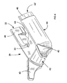
- a jigsaw 10 embodying the present invention is shown.
- the jigsaw comprises a body 12 in which a motor and gearbox (not shown) are disposed.
- a reciprocating shaft 14 extends from a gearbox housing 15 and comprises a clamp 16 at one end into which a saw blade 18 can be disposed and securely held.
- the saw blade extends through an aperture in a footplate 28 which is arranged to be place on, and engage with a work-piece during use.
- the footplate is coupled to the housing 12 or gearbox housing 15 via a bridge member 20.
- the bridge member has an arc-shaped profile such that the footplate can be angled with respect to the housing thereby allowing bevel cuts to be made, as is common in jigsaws.
- a conduit or pipe 22 is detachably engaged to the shoe.
- the pipe engages with a portion of the bridge component 20 such that the pipe passes through a space between the bridge and the footplate28.
- the pipe has a large diameter end 24 and a relatively small cross-sectional area end 26.
- the large diameter end is arranged to be coupled to a vacuum cleaner of source of low pressure (compared to the ambient room pressure) so that, during use, air is drawn along the pipe from the small diameter end to the large diameter end.
- a vacuum cleaner of source of low pressure compared to the ambient room pressure
- the smaller diameter end 24 of the pipe 22 is coupled to a shroud 26.
- the shroud is generally U-shaped and defines a volume into which a portion of the saw blade enters through a slot 30 formed in the shroud.
- the blade is free to reciprocate during use through the slot.
- the volume defined by the shroud has two openings 32 to which the pipe 22 can be attached; the pipe is attachable to either opening.
- an operating vacuum source is attached to the pipe air flows through the volume from one opening (not having the pipe attached), across the front of the saw blade in a direction perpendicular to the cut direction of the blade and out of the volume through the opening to which the pipe is attached.
- a large proportion of debris ejected by the saw into the volume becomes entrained in the airflow and is removed from the immediate vicinity of the saw blade/work-piece engagement area by the moving air.
- the air flow is predominately lamina through the volume, although there will be turbulent flow areas, typically around the saw blade.
- the cross-sectional area of the volume within the shroud is greater at the base of the U-shaped shroud in the vicinity of the blade than the cross-sectional area of the volume at either opening end of the shroud.
- the shroud can be securely disposed on the footplate such that it generally wraps around the blade and an orbital-action mechanism 34 such as a bell crank. As a result, it is possible to minimise debris escaping the shroud and entering mechanisms where it might contribute to the wear of components over a length of time.
- the shroud can be arranged to be removably disposed on the footplate between the bridge component 20 and a safety guard 36.
- the shroud does not hinder the normal operational characteristics of the jigsaw.
- the pipe 22 can be removaby disposed on the footplate.
- a latch mechanism 38 can be used to secure the pipe in position, where the latch is resiliently urged into engagement with a cooperating component of the bridge.
- the system shown in figure is further shown from a different angle. From this viewpoint the other opening 32' of the shroud can be seen.
- the pipe is not connected to this opening 32'.
- the shroud is arranged to be symmetrical such that the opening 32' is disposed in a position close to the bridge component 20.
- the airflow through the shroud when a vacuum source is coupled to the pipe is in the opposite direction to the arrangement described above, of course.
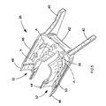
- FIG 3 the arrangement shown in figure 1 is shown again, however, some components of the jigsaw are not shown for clarity.
- This figure does not show the jigsaw body, gearbox housing, blade clamp or saw blade, for instance.
- Both openings 32 and 32' of the shroud 26 are arranged to extend into a position close to the bridge component 20, as described above.
- the pipe is arranged to be properly located such that the small diameter end 24 engages with or is coupled to an opening of the shroud. Because of the shroud's symmetry, the pipe can be arranged to couple to either opening 32 or 32'. As a result the operator is able to choose on which side of the jigsaw the pipe is to be placed so as to cause lease disruption or obscuration during use. The efficiency of debris removal from the cut area is not dependent on the location of the pipe.
- the pipe comprises a resilient member 38 arranged to cooperate with a portion of the bridge member 20.
- the resilient member is arranged to positively engage with this portion of the bridge to ensure proper location of the pipe on the footplate. Furthermore, the operator is able to see that the pipe is properly located when the resilient member has engaged with the portion of the bridge component.
- FIG. 4 shows the top side of the shroud and figure 5 shows the shroud's underside.
- the shroud comprises tangs 40 extending from a front portion 42 of the shroud. These tangs provide a convenient means by which the shroud can be manually placed on or removed from the jigsaw footplate.
- the underside edge 44 of the shroud is arranged to locate with cooperating components formed on the jigsaw footplate or shoe to secure the shroud in position during normal usage.
- each opening 32 or 32' of the shroud comprises a depressed portion 46 arranged to cooperate with a tang formed on the pipe to assist with locating the pipe and the shoe for proper use thereof.
- FIG. 5 the underside of the shroud is shown.
- Arrows A indicate the direction of airflow when the pipe and vacuum source are attached to opening 32', and when the shroud is disposed on a jigsaw footplate which in turn is disposed on a work-piece.
- the airflow is along one arm 48 of the U-shaped shroud, across the front portion 42 of the shroud and down the other arm 50 to the opening 32' and thence along the pipe and eventually to the source of the vacuum.
- the shroud is made from a transparent plastic material to enable the operator to view the area of the work-piece being cut. Acrylic or other similar material might be suitable.
Landscapes
- Engineering & Computer Science (AREA)
- Mechanical Engineering (AREA)
- Sawing (AREA)
- Control And Other Processes For Unpacking Of Materials (AREA)
Claims (12)
- Outil de découpe manuel actionné électriquement (10) comprenant :■ un logement (12) dans lequel un moteur électrique est disposé pour commander l'outil, ledit moteur ayant une sortie couplée à un arbre alternatif (14),■ une pince (16) disposée à une extrémité de l'arbre pour maintenir une lame de scie (18), dans laquelle, pendant l'utilisation, la lame de scie disposée dans la pince s'étend à travers une ouverture formée dans une base (28) disposée de façon à mettre en prise une pièce à travailler,■ un conduit (22) disposé de façon à enlever une portion de copeaux éjectés de la lame de scie pendant une opération de découpe, dans lequel le conduit comprend en outre un carénage (26) disposé de façon à couvrir une partie de l'ouverture, ledit carénage comprenant une fente (30) à travers laquelle une portion de la lame peut passer, caractérisé en ce que, lorsque le carénage est disposé sur la base et que la base est disposée sur la pièce à travailler, le carénage, la base et la pièce à travailler définissent un volume agencé, de sorte qu'une partie de la lame de scie sur laquelle se trouvent des dents de coupe entre dans le volume à travers la fente pendant l'utilisation, et la pince et/ou l'arbre alternatif soit(soient) exclus du volume.
- Outil selon la revendication 1, dans lequel le carénage et le conduit sont séparables.
- Outil selon la revendication 1, dans lequel le conduit est disposé de façon à être raccordé à une source de basse pression.
- Outil selon la revendication 1, dans lequel le volume comprend une entrée (32) et une sortie (32') de flux d'air, ladite sortie de flux d'air étant raccordée soit à la source de pression inférieure à la pression ambiante, soit au conduit.
- Outil selon la revendication 4, dans lequel le carénage est disposé de façon à définir un volume tel que, pendant l'utilisation, l'air passe à travers une superficie de la pièce à travailler coupée par la lame dans une direction (A) transversale au sens de coupe.
- Outil selon la revendication 4, dans lequel le conduit peut être raccordé à l'entrée de flux d'air.
- Outil selon les revendications 1 ou 6, dans lequel le conduit se met en prise, de manière détachable, avec la base.
- Outil selon la revendication 4, dans lequel l'entrée et la sortie de flux d'air s'étendent respectivement le long de chaque côté de la lame de scie, disposée dans la pince.
- Outil selon la revendication 1, dans lequel le conduit est mis en prise de façon détachable avec un composant de pont (20) de la base, disposé de façon à relier la base au logement.
- Outil selon la revendication 9, dans lequel la base se déplace entre une position droite et une position inclinée relativement au logement, afin de faciliter la découpe en biseau, et le conduit peut être disposé sur la base, dans une première ou une seconde position de chaque côté d'un axe central, de sorte que, lorsque la base est dans la position droite, le conduit puisse être disposé soit dans la première, soit dans la seconde position.
- Outil selon la revendication 10, dans lequel, quand la base est dans la position inclinée, le conduit peut être disposé dans la première position uniquement.
- Outil selon la revendication 1, dans lequel le carénage est transparent.
Priority Applications (6)
| Application Number | Priority Date | Filing Date | Title |
|---|---|---|---|
| AT06251458T ATE419086T1 (de) | 2006-03-18 | 2006-03-18 | Stichsäge mit vorrichtung zur späneabfuhr |
| DE602006004552T DE602006004552D1 (de) | 2006-03-18 | 2006-03-18 | Stichsäge mit Vorrichtung zur Späneabfuhr |
| EP06251458A EP1834723B1 (fr) | 2006-03-18 | 2006-03-18 | Scie sauteuse avec dispositif d'évacuation de copeaux |
| AU2006202619A AU2006202619B2 (en) | 2006-03-18 | 2006-06-16 | Debris removal apparatus for a jigsaw |
| US11/475,332 US7497017B2 (en) | 2006-03-18 | 2006-06-27 | Debris removal apparatus for a jigsaw |
| CNB2007100878073A CN100553842C (zh) | 2006-03-18 | 2007-03-19 | 电动手持式切割工具 |
Applications Claiming Priority (1)
| Application Number | Priority Date | Filing Date | Title |
|---|---|---|---|
| EP06251458A EP1834723B1 (fr) | 2006-03-18 | 2006-03-18 | Scie sauteuse avec dispositif d'évacuation de copeaux |
Publications (2)
| Publication Number | Publication Date |
|---|---|
| EP1834723A1 EP1834723A1 (fr) | 2007-09-19 |
| EP1834723B1 true EP1834723B1 (fr) | 2008-12-31 |
Family
ID=37075835
Family Applications (1)
| Application Number | Title | Priority Date | Filing Date |
|---|---|---|---|
| EP06251458A Expired - Lifetime EP1834723B1 (fr) | 2006-03-18 | 2006-03-18 | Scie sauteuse avec dispositif d'évacuation de copeaux |
Country Status (6)
| Country | Link |
|---|---|
| US (1) | US7497017B2 (fr) |
| EP (1) | EP1834723B1 (fr) |
| CN (1) | CN100553842C (fr) |
| AT (1) | ATE419086T1 (fr) |
| AU (1) | AU2006202619B2 (fr) |
| DE (1) | DE602006004552D1 (fr) |
Families Citing this family (14)
| Publication number | Priority date | Publication date | Assignee | Title |
|---|---|---|---|---|
| DE602006004552D1 (de) * | 2006-03-18 | 2009-02-12 | Black & Decker Inc | Stichsäge mit Vorrichtung zur Späneabfuhr |
| DE102006000200A1 (de) * | 2006-04-27 | 2007-10-31 | Hilti Ag | Elektrohandsäge mit Absaugvorrichtung |
| US20090077819A1 (en) * | 2007-09-21 | 2009-03-26 | Black & Decker Inc. | Cutting Angle Indicator in Jigsaw Housing with Positive Lock in Separately Assembled Shoe Sub-Assembly |
| US9981327B2 (en) | 2007-09-21 | 2018-05-29 | Black & Decker Inc. | Cutting angle indicator in jigsaw housing with dust extraction |
| DE102007056381A1 (de) * | 2007-11-22 | 2009-05-28 | Hilti Aktiengesellschaft | Handwerkzeugmaschine |
| US8549759B2 (en) | 2008-07-25 | 2013-10-08 | Milwaukee Electric Tool Corporation | Adjustable shoe for a power tool |
| US8549760B2 (en) * | 2008-07-25 | 2013-10-08 | Milwaukee Electric Tool Corporation | Adjustable locking shoe |
| DE102009055827A1 (de) * | 2009-11-26 | 2011-06-01 | Festool Gmbh | Hand-Werkzeugmaschine mit einer Gleitsohle |
| US10413980B2 (en) | 2011-04-01 | 2019-09-17 | Milwaukee Electric Tool Corporation | Reciprocating saw, such as a jigsaw |
| JP5620709B2 (ja) * | 2010-04-28 | 2014-11-05 | 株式会社マキタ | 切断工具 |
| JP5526003B2 (ja) * | 2010-11-19 | 2014-06-18 | 株式会社マキタ | 切断機 |
| US12070809B2 (en) | 2019-03-01 | 2024-08-27 | Milwaukee Electric Tool Corporation | Band saw |
| DE102020132285A1 (de) * | 2020-10-28 | 2022-04-28 | Festool Gmbh | Absaugvorrichtung sowie damit ausgestattete Hand-Sägemaschine |
| DE102021215109A1 (de) | 2021-12-30 | 2023-07-06 | Robert Bosch Gesellschaft mit beschränkter Haftung | Stichsäge mit Befestigungselement für Absaugstutzen |
Family Cites Families (17)
| Publication number | Priority date | Publication date | Assignee | Title |
|---|---|---|---|---|
| US3938251A (en) | 1975-03-10 | 1976-02-17 | The Raymond Lee Organization, Inc. | Saber or jig saw with demountable foot plate and shield |
| DE2546527C2 (de) * | 1975-10-17 | 1993-05-27 | Robert Bosch Gmbh, 7000 Stuttgart | Stichsäge |
| DE3420442A1 (de) * | 1984-06-01 | 1985-12-05 | Festo KG, 7300 Esslingen | Stichsaege |
| DE3712236A1 (de) * | 1987-04-10 | 1988-10-27 | Bosch Gmbh Robert | Stichsaege |
| DE3820752A1 (de) | 1988-06-18 | 1989-12-21 | Reich Maschf Gmbh Karl | Stichsaege mit absaugung |
| USD339276S (en) * | 1991-04-12 | 1993-09-14 | Hitachi Koki Co., Ltd. | Portable electric jigsaw |
| JP3251456B2 (ja) * | 1995-03-10 | 2002-01-28 | 株式会社マキタ | ジグソーの吸塵装置 |
| USD409469S (en) * | 1998-02-10 | 1999-05-11 | Makita Corporation | Portable electric jig saw |
| US6230411B1 (en) * | 1998-07-10 | 2001-05-15 | Porter-Cable Corporation | Blade guide system for a jigsaw |
| USD440474S1 (en) * | 1999-11-22 | 2001-04-17 | Choon Nang Electrical Appliance Mfy., Ltd. | Electric jigsaw |
| USD474384S1 (en) * | 2001-09-15 | 2003-05-13 | Politec Power Tools (Europe) Ltd. | Jigsaw power tool |
| GB2399315A (en) * | 2003-03-13 | 2004-09-15 | Black & Decker Inc | Method and apparatus for removing dust from a workpiece |
| GB2399537A (en) * | 2003-03-13 | 2004-09-22 | Black & Decker Inc | Method and apparatus for removing dust from a workpiece |
| US7296356B2 (en) * | 2004-04-14 | 2007-11-20 | Eastway Fair Company Limited | Toolless adjustable base for a portable saw |
| USD523311S1 (en) * | 2004-09-17 | 2006-06-20 | Black & Decker Inc. | Jigsaw |
| EP1790432B1 (fr) * | 2005-11-28 | 2014-01-08 | Black & Decker, Inc. | Outil motorisé tel que scie sauteuse pourvu de moyens pour dégager les débris de coupe d'une pièce |
| DE602006004552D1 (de) * | 2006-03-18 | 2009-02-12 | Black & Decker Inc | Stichsäge mit Vorrichtung zur Späneabfuhr |
-
2006
- 2006-03-18 DE DE602006004552T patent/DE602006004552D1/de not_active Expired - Lifetime
- 2006-03-18 AT AT06251458T patent/ATE419086T1/de not_active IP Right Cessation
- 2006-03-18 EP EP06251458A patent/EP1834723B1/fr not_active Expired - Lifetime
- 2006-06-16 AU AU2006202619A patent/AU2006202619B2/en not_active Ceased
- 2006-06-27 US US11/475,332 patent/US7497017B2/en not_active Expired - Fee Related
-
2007
- 2007-03-19 CN CNB2007100878073A patent/CN100553842C/zh not_active Expired - Fee Related
Also Published As
| Publication number | Publication date |
|---|---|
| EP1834723A1 (fr) | 2007-09-19 |
| CN100553842C (zh) | 2009-10-28 |
| ATE419086T1 (de) | 2009-01-15 |
| CN101036952A (zh) | 2007-09-19 |
| AU2006202619A1 (en) | 2007-10-04 |
| AU2006202619B2 (en) | 2012-01-19 |
| US7497017B2 (en) | 2009-03-03 |
| US20070214659A1 (en) | 2007-09-20 |
| DE602006004552D1 (de) | 2009-02-12 |
Similar Documents
| Publication | Publication Date | Title |
|---|---|---|
| CN100553842C (zh) | 电动手持式切割工具 | |
| EP1415746B1 (fr) | Outil motorisé | |
| US8371034B2 (en) | Dust collection cover attachable to cutter | |
| US6827640B2 (en) | Portable dust collection system | |
| CN106163751B (zh) | 用于台锯的气流和照明系统 | |
| CN100436016C (zh) | 从工件上除去碎屑的方法和装置 | |
| US20090183800A1 (en) | Dust shroud for gas powered circular saws | |
| US20090165312A1 (en) | Hand-held power tool | |
| CN1506194A (zh) | 手持式电动工具机 | |
| EP1790432B1 (fr) | Outil motorisé tel que scie sauteuse pourvu de moyens pour dégager les débris de coupe d'une pièce | |
| EP3715032B1 (fr) | Scie alternative | |
| US6173499B1 (en) | Vent cover for an electric saw | |
| EP2463049B1 (fr) | Découpeuse | |
| CN201537747U (zh) | 切割机 | |
| CN215661162U (zh) | 集尘装置以及手工锯切工具 | |
| US20070033807A1 (en) | Planer with improved chip removal | |
| US20260097443A1 (en) | Circular saw | |
| JPH06335904A (ja) | 電動丸鋸の集塵機構 | |
| CN217123077U (zh) | 电动工具 | |
| JP2000141307A (ja) | 糸鋸盤 | |
| GB2348848A (en) | Jig saw dust blower |
Legal Events
| Date | Code | Title | Description |
|---|---|---|---|
| PUAI | Public reference made under article 153(3) epc to a published international application that has entered the european phase |
Free format text: ORIGINAL CODE: 0009012 |
|
| AK | Designated contracting states |
Kind code of ref document: A1 Designated state(s): AT BE BG CH CY CZ DE DK EE ES FI FR GB GR HU IE IS IT LI LT LU LV MC NL PL PT RO SE SI SK TR |
|
| AX | Request for extension of the european patent |
Extension state: AL BA HR MK YU |
|
| 17P | Request for examination filed |
Effective date: 20070928 |
|
| 17Q | First examination report despatched |
Effective date: 20071105 |
|
| REG | Reference to a national code |
Ref country code: SE Ref legal event code: TRGR |
|
| AKX | Designation fees paid |
Designated state(s): AT BE BG CH CY CZ DE DK EE ES FI FR GB GR HU IE IS IT LI LT LU LV MC NL PL PT RO SE SI SK TR |
|
| GRAP | Despatch of communication of intention to grant a patent |
Free format text: ORIGINAL CODE: EPIDOSNIGR1 |
|
| GRAS | Grant fee paid |
Free format text: ORIGINAL CODE: EPIDOSNIGR3 |
|
| GRAA | (expected) grant |
Free format text: ORIGINAL CODE: 0009210 |
|
| AK | Designated contracting states |
Kind code of ref document: B1 Designated state(s): AT BE BG CH CY CZ DE DK EE ES FI FR GB GR HU IE IS IT LI LT LU LV MC NL PL PT RO SE SI SK TR |
|
| REG | Reference to a national code |
Ref country code: GB Ref legal event code: FG4D Ref country code: CH Ref legal event code: EP |
|
| REF | Corresponds to: |
Ref document number: 602006004552 Country of ref document: DE Date of ref document: 20090212 Kind code of ref document: P |
|
| REG | Reference to a national code |
Ref country code: IE Ref legal event code: FG4D |
|
| PG25 | Lapsed in a contracting state [announced via postgrant information from national office to epo] |
Ref country code: PL Free format text: LAPSE BECAUSE OF FAILURE TO SUBMIT A TRANSLATION OF THE DESCRIPTION OR TO PAY THE FEE WITHIN THE PRESCRIBED TIME-LIMIT Effective date: 20081231 Ref country code: NL Free format text: LAPSE BECAUSE OF FAILURE TO SUBMIT A TRANSLATION OF THE DESCRIPTION OR TO PAY THE FEE WITHIN THE PRESCRIBED TIME-LIMIT Effective date: 20081231 Ref country code: LV Free format text: LAPSE BECAUSE OF FAILURE TO SUBMIT A TRANSLATION OF THE DESCRIPTION OR TO PAY THE FEE WITHIN THE PRESCRIBED TIME-LIMIT Effective date: 20081231 Ref country code: SI Free format text: LAPSE BECAUSE OF FAILURE TO SUBMIT A TRANSLATION OF THE DESCRIPTION OR TO PAY THE FEE WITHIN THE PRESCRIBED TIME-LIMIT Effective date: 20081231 Ref country code: FI Free format text: LAPSE BECAUSE OF FAILURE TO SUBMIT A TRANSLATION OF THE DESCRIPTION OR TO PAY THE FEE WITHIN THE PRESCRIBED TIME-LIMIT Effective date: 20081231 |
|
| NLV1 | Nl: lapsed or annulled due to failure to fulfill the requirements of art. 29p and 29m of the patents act | ||
| PG25 | Lapsed in a contracting state [announced via postgrant information from national office to epo] |
Ref country code: ES Free format text: LAPSE BECAUSE OF FAILURE TO SUBMIT A TRANSLATION OF THE DESCRIPTION OR TO PAY THE FEE WITHIN THE PRESCRIBED TIME-LIMIT Effective date: 20090411 Ref country code: LT Free format text: LAPSE BECAUSE OF FAILURE TO SUBMIT A TRANSLATION OF THE DESCRIPTION OR TO PAY THE FEE WITHIN THE PRESCRIBED TIME-LIMIT Effective date: 20081231 Ref country code: BE Free format text: LAPSE BECAUSE OF FAILURE TO SUBMIT A TRANSLATION OF THE DESCRIPTION OR TO PAY THE FEE WITHIN THE PRESCRIBED TIME-LIMIT Effective date: 20081231 Ref country code: EE Free format text: LAPSE BECAUSE OF FAILURE TO SUBMIT A TRANSLATION OF THE DESCRIPTION OR TO PAY THE FEE WITHIN THE PRESCRIBED TIME-LIMIT Effective date: 20081231 Ref country code: RO Free format text: LAPSE BECAUSE OF FAILURE TO SUBMIT A TRANSLATION OF THE DESCRIPTION OR TO PAY THE FEE WITHIN THE PRESCRIBED TIME-LIMIT Effective date: 20081231 |
|
| PG25 | Lapsed in a contracting state [announced via postgrant information from national office to epo] |
Ref country code: PT Free format text: LAPSE BECAUSE OF FAILURE TO SUBMIT A TRANSLATION OF THE DESCRIPTION OR TO PAY THE FEE WITHIN THE PRESCRIBED TIME-LIMIT Effective date: 20090601 Ref country code: AT Free format text: LAPSE BECAUSE OF FAILURE TO SUBMIT A TRANSLATION OF THE DESCRIPTION OR TO PAY THE FEE WITHIN THE PRESCRIBED TIME-LIMIT Effective date: 20081231 Ref country code: IS Free format text: LAPSE BECAUSE OF FAILURE TO SUBMIT A TRANSLATION OF THE DESCRIPTION OR TO PAY THE FEE WITHIN THE PRESCRIBED TIME-LIMIT Effective date: 20090430 Ref country code: CZ Free format text: LAPSE BECAUSE OF FAILURE TO SUBMIT A TRANSLATION OF THE DESCRIPTION OR TO PAY THE FEE WITHIN THE PRESCRIBED TIME-LIMIT Effective date: 20081231 |
|
| PG25 | Lapsed in a contracting state [announced via postgrant information from national office to epo] |
Ref country code: SK Free format text: LAPSE BECAUSE OF FAILURE TO SUBMIT A TRANSLATION OF THE DESCRIPTION OR TO PAY THE FEE WITHIN THE PRESCRIBED TIME-LIMIT Effective date: 20081231 |
|
| PG25 | Lapsed in a contracting state [announced via postgrant information from national office to epo] |
Ref country code: DK Free format text: LAPSE BECAUSE OF FAILURE TO SUBMIT A TRANSLATION OF THE DESCRIPTION OR TO PAY THE FEE WITHIN THE PRESCRIBED TIME-LIMIT Effective date: 20081231 Ref country code: MC Free format text: LAPSE BECAUSE OF NON-PAYMENT OF DUE FEES Effective date: 20090331 |
|
| PLBE | No opposition filed within time limit |
Free format text: ORIGINAL CODE: 0009261 |
|
| STAA | Information on the status of an ep patent application or granted ep patent |
Free format text: STATUS: NO OPPOSITION FILED WITHIN TIME LIMIT |
|
| 26N | No opposition filed |
Effective date: 20091001 |
|
| REG | Reference to a national code |
Ref country code: FR Ref legal event code: ST Effective date: 20091130 |
|
| REG | Reference to a national code |
Ref country code: IE Ref legal event code: MM4A |
|
| PG25 | Lapsed in a contracting state [announced via postgrant information from national office to epo] |
Ref country code: IE Free format text: LAPSE BECAUSE OF NON-PAYMENT OF DUE FEES Effective date: 20090318 Ref country code: BG Free format text: LAPSE BECAUSE OF FAILURE TO SUBMIT A TRANSLATION OF THE DESCRIPTION OR TO PAY THE FEE WITHIN THE PRESCRIBED TIME-LIMIT Effective date: 20090331 |
|
| PG25 | Lapsed in a contracting state [announced via postgrant information from national office to epo] |
Ref country code: FR Free format text: LAPSE BECAUSE OF NON-PAYMENT OF DUE FEES Effective date: 20091123 |
|
| PG25 | Lapsed in a contracting state [announced via postgrant information from national office to epo] |
Ref country code: GR Free format text: LAPSE BECAUSE OF FAILURE TO SUBMIT A TRANSLATION OF THE DESCRIPTION OR TO PAY THE FEE WITHIN THE PRESCRIBED TIME-LIMIT Effective date: 20090401 |
|
| REG | Reference to a national code |
Ref country code: CH Ref legal event code: PL |
|
| PG25 | Lapsed in a contracting state [announced via postgrant information from national office to epo] |
Ref country code: LI Free format text: LAPSE BECAUSE OF NON-PAYMENT OF DUE FEES Effective date: 20100331 Ref country code: CH Free format text: LAPSE BECAUSE OF NON-PAYMENT OF DUE FEES Effective date: 20100331 |
|
| PG25 | Lapsed in a contracting state [announced via postgrant information from national office to epo] |
Ref country code: IT Free format text: LAPSE BECAUSE OF FAILURE TO SUBMIT A TRANSLATION OF THE DESCRIPTION OR TO PAY THE FEE WITHIN THE PRESCRIBED TIME-LIMIT Effective date: 20081231 |
|
| PG25 | Lapsed in a contracting state [announced via postgrant information from national office to epo] |
Ref country code: LU Free format text: LAPSE BECAUSE OF NON-PAYMENT OF DUE FEES Effective date: 20090318 |
|
| PG25 | Lapsed in a contracting state [announced via postgrant information from national office to epo] |
Ref country code: HU Free format text: LAPSE BECAUSE OF FAILURE TO SUBMIT A TRANSLATION OF THE DESCRIPTION OR TO PAY THE FEE WITHIN THE PRESCRIBED TIME-LIMIT Effective date: 20090701 |
|
| PG25 | Lapsed in a contracting state [announced via postgrant information from national office to epo] |
Ref country code: TR Free format text: LAPSE BECAUSE OF FAILURE TO SUBMIT A TRANSLATION OF THE DESCRIPTION OR TO PAY THE FEE WITHIN THE PRESCRIBED TIME-LIMIT Effective date: 20081231 |
|
| PG25 | Lapsed in a contracting state [announced via postgrant information from national office to epo] |
Ref country code: CY Free format text: LAPSE BECAUSE OF FAILURE TO SUBMIT A TRANSLATION OF THE DESCRIPTION OR TO PAY THE FEE WITHIN THE PRESCRIBED TIME-LIMIT Effective date: 20081231 |
|
| PGFP | Annual fee paid to national office [announced via postgrant information from national office to epo] |
Ref country code: GB Payment date: 20190313 Year of fee payment: 14 Ref country code: DE Payment date: 20190305 Year of fee payment: 14 |
|
| PGFP | Annual fee paid to national office [announced via postgrant information from national office to epo] |
Ref country code: SE Payment date: 20190311 Year of fee payment: 14 |
|
| REG | Reference to a national code |
Ref country code: DE Ref legal event code: R119 Ref document number: 602006004552 Country of ref document: DE |
|
| PG25 | Lapsed in a contracting state [announced via postgrant information from national office to epo] |
Ref country code: DE Free format text: LAPSE BECAUSE OF NON-PAYMENT OF DUE FEES Effective date: 20201001 Ref country code: SE Free format text: LAPSE BECAUSE OF NON-PAYMENT OF DUE FEES Effective date: 20200319 |
|
| GBPC | Gb: european patent ceased through non-payment of renewal fee |
Effective date: 20200318 |
|
| PG25 | Lapsed in a contracting state [announced via postgrant information from national office to epo] |
Ref country code: GB Free format text: LAPSE BECAUSE OF NON-PAYMENT OF DUE FEES Effective date: 20200318 |