EP1415882A1 - Drehgestell für ein Schienenfahrzeug - Google Patents
Drehgestell für ein Schienenfahrzeug Download PDFInfo
- Publication number
- EP1415882A1 EP1415882A1 EP20030024926 EP03024926A EP1415882A1 EP 1415882 A1 EP1415882 A1 EP 1415882A1 EP 20030024926 EP20030024926 EP 20030024926 EP 03024926 A EP03024926 A EP 03024926A EP 1415882 A1 EP1415882 A1 EP 1415882A1
- Authority
- EP
- European Patent Office
- Prior art keywords
- truck
- end beam
- railroad car
- side frames
- antenna
- Prior art date
- Legal status (The legal status is an assumption and is not a legal conclusion. Google has not performed a legal analysis and makes no representation as to the accuracy of the status listed.)
- Granted
Links
Images



Classifications
-
- B—PERFORMING OPERATIONS; TRANSPORTING
- B61—RAILWAYS
- B61F—RAIL VEHICLE SUSPENSIONS, e.g. UNDERFRAMES, BOGIES OR ARRANGEMENTS OF WHEEL AXLES; RAIL VEHICLES FOR USE ON TRACKS OF DIFFERENT WIDTH; PREVENTING DERAILING OF RAIL VEHICLES; WHEEL GUARDS, OBSTRUCTION REMOVERS OR THE LIKE FOR RAIL VEHICLES
- B61F5/00—Constructional details of bogies; Connections between bogies and vehicle underframes; Arrangements or devices for adjusting or allowing self-adjustment of wheel axles or bogies when rounding curves
- B61F5/50—Other details
- B61F5/52—Bogie frames
-
- B—PERFORMING OPERATIONS; TRANSPORTING
- B61—RAILWAYS
- B61F—RAIL VEHICLE SUSPENSIONS, e.g. UNDERFRAMES, BOGIES OR ARRANGEMENTS OF WHEEL AXLES; RAIL VEHICLES FOR USE ON TRACKS OF DIFFERENT WIDTH; PREVENTING DERAILING OF RAIL VEHICLES; WHEEL GUARDS, OBSTRUCTION REMOVERS OR THE LIKE FOR RAIL VEHICLES
- B61F3/00—Types of bogies
Definitions
- the present invention relates to a truck for railroad car, and particularly to a truck for railroad car including an end beam for supporting an instrument.
- a truck for railroad car there is known one having an H-shaped, when viewed in plan, truck frame in which a transom is connected to intermediate portions, in a longitudinal direction of a railroad car, of side frames extending substantially in parallel at both right and left sides of a truck (for example, see JP-A-11-29040).
- an end beam a beam extending in a lateral direction of the truck
- the instrument is supported at the end beam.
- Both end portions of the end beam as stated above are attached to the end portions (the rear end portions or front end portions) of the side frames of the truck.
- This attachment is typically performed by welding, or by bolt coupling. That is, the attachment of the end beam to the side frames is generally rigid connection.
- a railroad on which a railroad car (truck) travels is constituted by two right and left rails, they are not always provided horizontally and in parallel according to the state of the ground on which the rails are installed.
- the relative positions of the right and left side frames of the truck are shifted in the vertical direction, and the truck frame is deformed such that the truck frame is deformed under torsion relative to the transom.
- the amount of deformation of the truck frame near the transom is small, the amount of deformation of the truck frame near the end beam distant from the transom becomes large.
- the present invention has been made to solve the above problem, and has an object to provide a truck for railroad car which can absorb and reduce deformation by torsional force acting on an end beam.
- a truck for railroad car comprising an H-shaped, when viewed in plan, truck frame including side frames extending substantially in parallel at both right and left sides of the truck for railroad car, and a transom connected to intermediate portions of the side frames, the intermediate portions being substantially at a center in a longitudinal direction of a railroad car, an end beam extending in a lateral direction of the railroad car and connected to end portions of the right and left side frames of the truck frame, an instrument being supported by the end beam, and deformation absorbing means provided at both sides of a portion of the end beam where the instrument is supported, for absorbing torsional force acting on the end beam.
- the deformation absorbing means may be provided at any position as long as the torsional force acting on the end beam can be absorbed and reduced, and may be located at any portion on both right and left sides of the instrument between the side frames.
- both end portions of the end beam may be directly softly connected to the end portions (front end portions or rear end portions) of the side frames with the deformation absorbing means placed in the end beam.
- the deformation absorbing means may be any means as long as the torsional force acting on the end beam can be absorbed, and for example, the elasticity of elastic rubber, or the elasticity of a plate spring or a coil spring can be used.
- the end beam when the truck frame is deformed under torsion, the end beam starts to be significantly deformed under torsion, however, the torsional force is absorbed and reduced by the deformation absorbing means provided at the end beam. Since the deformation absorbing means are provided at both sides of the portion of the end beam where the instrument is supported, the torsional force does not act on the attachment portion of the instrument.
- the end beam includes right and left support brackets whose outer edges are connected to the right and left side frames, and a center bar connected to inner end portions of the right and left support brackets through the deformation absorbing means and having an instrument attachment portion, each of the deformation absorbing means is constructed by a rubber bush including an outer cylindrical member, a center shaft member, and an elastic rubber member provided therebetween, the outer cylindrical members are respectively connected to end portions of the center bar, and the center shaft members are respectively connected to the right and left brackets.
- the rubber bushes are used to softly connect the end beam to the side frames, even if the outer cylindrical member connected to the end portion of the center bar and the center shaft member connected to the support bracket (side frame) are relatively shifted, the displacement is naturally absorbed by the deformation of the elastic rubber member.
- the rubber bush is used as the deformation absorbing means, the torsional force acting on the end beam can be absorbed and reduced.
- the end beam comprises the right and left support brackets whose outer ends are connected to the right and left side frames, and the center bar provided between the right and left support brackets, and the deformation absorbing means are provided between the left support brackets and the center bar and between the right support brackets and the center bar.
- the rubber bushes can be assembled before the end beam is attached to the side frames, or after the right and left support brackets are attached to the side frames, the center bar can also be attached through the rubber bushes.
- the instrument is an antenna device supported by means of an antenna support member, and a wiring attachment portion for fixing a wire to the antenna device may be provided at the center bar.
- the wire to the antenna device can be stably attached and supported by the wiring attachment portion.
- the wire connected to the antenna device is once supported by the center bar, compulsory force does not act on the wire even if the end beam is deformed.
- the wiring from the side frame to the antenna device through the wiring attachment portion of the center bar (end beam) is formed, and the wire is supported by the wiring attachment portion, so that the wire does not have influence on other areas and other components in the truck.
- Fig. 1 is a front view showing a truck for railroad car of an embodiment of the invention.
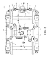
- Fig. 2 is a plan view showing a truck for railroad car of an embodiment of the invention.
- Fig. 3 is an explanatory view of a train composition.
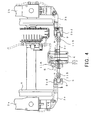
- Fig. 4 is a plan view showing a vicinity of an end beam.
- Fig. 5 is a rear view showing a vicinity of an end beam.
- Fig. 1 is a front view showing a truck for railroad car of the embodiment of the invention
- Fig. 2 is a plan view of the same
- Fig. 3 is an explanatory view of a train composition.
- a truck 1 for railroad car of the invention includes an H-shaped, when viewed in plan, truck frame 2.
- This truck frame 2 includes side frames 2a and 2b extending substantially in parallel at both right and left sides thereof, and a transom 2c connected to intermediate portions of the side frames 2a and 2b.
- the intermediate portions are located substantially at a center in the longitudinal direction of the railroad car.
- the rear ends of the right and left side frames 2a and 2b of the truck frame 2 are connected through an end beam 3 extending in the lateral direction of the railroad car, and an antenna device A (see Fig. 4) as an instrument is attached to the end beam 3 by an antenna support member 4 so as to be supported by the antenna support member 4.
- the end beam 3 includes antenna brackets 3a and 3b as right and left support brackets and a center bar 3c.
- the outer end portions of the antenna brackets 3a and 3b are connected and fixed to the rear end portions of the right and left side frames 2a and 2b by fastening tools 5 (bolts or the like).
- the inner end portions of the right and left antenna brackets 3a and 3b are elastically connected to the right and left end portions of the center bar 3c through rubber bushes 6 and 7 (deformation absorbing means).
- the antenna support member 4 is provided substantially at the center position of this center bar 3c.
- the rubber bushes 6 and 7 are provided at the end beam 3, they are positioned at both sides of the antenna support member 4.
- the rubber bushes 6 and 7 include elastic rubber members 6a and 7a (elastic bodies), and in the case where the truck frame 2 causes deformation under torsion, the elastic deformation of the elastic rubber members 6a and 7a absorb the torsional force acting on the end beam 3.
- both end portions of the end beam 3 are rigidly connected to the side frames 2a and 2b, the support condition (rigidity) for supporting the heavy antenna device A (antenna support member 4) is secured, and the end beam can stably support it.
- the end beam 3 is not required to be provided on plural trucks in the train composition, and is provided on merely a specified truck. That is, for example, as shown in Fig. 3, in the case where a train is made up of two cars of railroad cars T1 and T2 and includes four trucks 1A to 1D, the end beam 3 is provided at the rear side of the one truck 1A. That is, the end beam 3 is not provided in the remaining trucks 1B to 1D.
- the rubber bushes 6 and 7 have the shaft center in the longitudinal direction of the truck as shown in Fig. 4 and Fig. 5, include outer cylindrical members 6b and 7b, center shaft members 6c and 7c, and the elastic rubber members 6a and 7a provided respectively between outer cylindrical member 6b and center shaft members 6c and between outer cylindrical member 7b and center shaft members 7c.
- the outer cylindrical members 6b and 7b are respectively connected to both end portions of the center bar 3c by welding.
- the center axial members 6c and 7c are attached and fixed to the center side end portions of the right and left antenna brackets 3a and 3b by screw means 9.
- support bracket portions 3ad and 3bd are integrally provided at the center side end portions of the right and left antenna brackets 3a and 3b by welding.
- the antenna brackets 3a and 3b include, as shown in Fig. 5, horizontal portions 3aa and 3ba extending toward the center side of the truck in the lateral direction from the vicinities of the side frames 2a and 2b in the horizontal direction, inclined portions 3ab and 3bb extending downward toward the center side of the truck in the lateral from the inner end portions of the horizontal portions 3aa and 3ba, and vertical portions 3ac and 3bc further extending vertically downward from the lower ends of the inclined portions 3ab and 3bb.
- the antenna brackets are connected to the right and left end portions of the center bar 3c through the rubber bushes 6 and 7, and elastically support the center bar 3c.
- the position where the center bar 3c is supported is lower than a line L connecting the centers of wheels 8.
- the right and left side frames 2a and 2b are relatively shifted relative to the transom 2c. More specifically, the center shaft members 6c and 7c of the right and left rubber bushes 6 and 7 connected to the antenna brackets 3a and 3b (the side frames 2a and 2b) are at different position in the vertical direction. On the other hand, since the outer cylindrical members 6b and 7b connected to the end portions of the center bar 3c keep substantially the same position in the vertical direction.
- the center shaft members 6c and 7c connected to the antenna brackets 3a and 3b are relatively displaced with respect to the outer cylindrical members 6b and 7b.
- the displacement of the center shaft members 6c and 7c is naturally absorbed by the deformation of the elastic rubber members 6a and 7a.
- the rubber bushes 6 and 7 of the simple structure as described before the torsional force acting on the end beam 3 can be naturally absorbed and reduced by the deformation of the elastic rubber members 6a and 7a.
- Wiring attachment portions 11A and 11B are provided at the upper side of the end beam 3 (the antenna brackets 3a and 3b, the center bar 3c) .
- a wire S extending to the antenna support member 4 (antenna device A) is fixed to the wiring attachments 11A and 11B. With this structure, wiring to the antenna device A is carried out without difficulty by using the end beam 3 having high support condition (high rigidity).
- a disk brake is adopted as the brake, and in the case where the disk brake is provided at the side frame or the end beam, when the rubber bushes 6 and 7 are provided at the end beam, the amount of deformation of the end beam 3 becomes large, and it becomes too soft.
- the truck be provided with a tread brake unit, as brake means, having a brake shoe coming in contact with the tread of a wheel. This is because, since the tread brake unit is normally provided at the transom having less deformation, high support condition is not required for the end beam contrary to the case where the disk brake is adopted.
- This invention is carried out as described above, and has effects as described below.
- the deformation absorbing means for absorbing the torsional force acting on the end beam are provided at both sides of the portion of the end beam where the instrument is supported, even if the truck frame is deformed and the end beam starts to be significantly deformed, the torsional force is naturally absorbed by the deformation absorbing means and can be reduced.
- the deformation absorbing means is constructed by the rubber bush including the outer cylindrical member, the center shaft member, and the elastic rubber member provided therebetween, the structure is not complicated.
Landscapes
- Engineering & Computer Science (AREA)
- Mechanical Engineering (AREA)
- Support Of Aerials (AREA)
- Train Traffic Observation, Control, And Security (AREA)
- Platform Screen Doors And Railroad Systems (AREA)
- Vibration Prevention Devices (AREA)
- Investigating Or Analyzing Materials By The Use Of Ultrasonic Waves (AREA)
- Escalators And Moving Walkways (AREA)
- Body Structure For Vehicles (AREA)
Applications Claiming Priority (2)
| Application Number | Priority Date | Filing Date | Title |
|---|---|---|---|
| JP2002315428A JP2004148948A (ja) | 2002-10-30 | 2002-10-30 | 鉄道車両用台車 |
| JP2002315428 | 2002-10-30 |
Publications (3)
| Publication Number | Publication Date |
|---|---|
| EP1415882A1 true EP1415882A1 (de) | 2004-05-06 |
| EP1415882B1 EP1415882B1 (de) | 2008-12-03 |
| EP1415882B2 EP1415882B2 (de) | 2018-08-08 |
Family
ID=32089522
Family Applications (1)
| Application Number | Title | Priority Date | Filing Date |
|---|---|---|---|
| EP03024926.2A Expired - Lifetime EP1415882B2 (de) | 2002-10-30 | 2003-10-29 | Drehgestell für ein Schienenfahrzeug |
Country Status (6)
| Country | Link |
|---|---|
| US (1) | US7004078B2 (de) |
| EP (1) | EP1415882B2 (de) |
| JP (1) | JP2004148948A (de) |
| AT (1) | ATE416112T1 (de) |
| CA (1) | CA2446992C (de) |
| DE (1) | DE60325004D1 (de) |
Cited By (5)
| Publication number | Priority date | Publication date | Assignee | Title |
|---|---|---|---|---|
| CN104334435A (zh) * | 2012-05-21 | 2015-02-04 | 新日铁住金株式会社 | 铁道车辆的转向架构架 |
| WO2016131691A1 (de) * | 2015-02-17 | 2016-08-25 | Siemens Ag Österreich | Verbindungsträger für zwei längsträger eines schienenfahrzeugs |
| US9919719B2 (en) | 2012-05-30 | 2018-03-20 | Bombardier Transportation Gmbh | Running gear frame for a rail vehicle |
| FR3074468A1 (fr) * | 2017-12-05 | 2019-06-07 | Alstom Transport Technologies | Bogie de vehicule ferroviaire |
| AT523656A1 (de) * | 2020-03-31 | 2021-10-15 | Siemens Mobility Austria Gmbh | Trageanordnung für ein Fahrwerk eines Schienenfahrzeugs |
Families Citing this family (9)
| Publication number | Priority date | Publication date | Assignee | Title |
|---|---|---|---|---|
| USD749984S1 (en) * | 2012-05-15 | 2016-02-23 | Kawasaki Jukogyo Kabushiki Kaisha | Bogie for railcar |
| JP5772761B2 (ja) * | 2012-08-13 | 2015-09-02 | 新日鐵住金株式会社 | 鉄道車両の台車枠 |
| CN105059305A (zh) * | 2015-08-31 | 2015-11-18 | 济南轨道交通装备有限责任公司 | 一种焊接转向架 |
| CN105109501B (zh) * | 2015-09-06 | 2017-10-03 | 中车青岛四方机车车辆股份有限公司 | 一种轨道车辆用附件安装装置及其安装方法 |
| CN105216823B (zh) * | 2015-09-30 | 2018-05-25 | 中车南京浦镇车辆有限公司 | 一种用于轨道车辆的天线设备固定装置 |
| CN106004915A (zh) * | 2016-06-21 | 2016-10-12 | 中车唐山机车车辆有限公司 | 转向架的构架 |
| JP6697352B2 (ja) * | 2016-08-22 | 2020-05-20 | 川崎重工業株式会社 | 鉄道車両用台車 |
| CN106809230B (zh) * | 2016-09-21 | 2018-02-09 | 比亚迪股份有限公司 | 转向架总成和跨座式单轨车辆 |
| KR101856592B1 (ko) * | 2016-10-20 | 2018-05-14 | 한국철도기술연구원 | 산악철도차량용 대차 구조 |
Citations (5)
| Publication number | Priority date | Publication date | Assignee | Title |
|---|---|---|---|---|
| US4173933A (en) * | 1974-05-08 | 1979-11-13 | Maschinenfabrik Augsburg-Nurnberg Aktiengesellschaft | High speed bogie |
| US4475463A (en) * | 1982-09-30 | 1984-10-09 | Amsted Industries Incorporated | Single axle truck transom assembly |
| EP0287161A1 (de) * | 1987-04-16 | 1988-10-19 | Werkspoor Services B.V. | Schienenfahrzeug mit entsprechendem Drehgestell |
| US5601030A (en) * | 1996-03-04 | 1997-02-11 | Brouillette; Michael F. | Railraod bogie, for connecting vehicles in an articulated train |
| JPH1129040A (ja) | 1997-07-14 | 1999-02-02 | Hitachi Ltd | 鉄道車両用台車 |
Family Cites Families (2)
| Publication number | Priority date | Publication date | Assignee | Title |
|---|---|---|---|---|
| US5924654A (en) * | 1997-10-06 | 1999-07-20 | Zeftek, Inc. | Railroad car sensing system |
| DE19919208A1 (de) * | 1999-04-28 | 2000-11-02 | Daimler Chrysler Ag | Einstellbares Drehgestell mit drei Radsätzen für ein Schienenfahrzeug |
-
2002
- 2002-10-30 JP JP2002315428A patent/JP2004148948A/ja active Pending
-
2003
- 2003-10-27 US US10/694,581 patent/US7004078B2/en not_active Expired - Lifetime
- 2003-10-27 CA CA002446992A patent/CA2446992C/en not_active Expired - Fee Related
- 2003-10-29 AT AT03024926T patent/ATE416112T1/de not_active IP Right Cessation
- 2003-10-29 DE DE60325004T patent/DE60325004D1/de not_active Expired - Lifetime
- 2003-10-29 EP EP03024926.2A patent/EP1415882B2/de not_active Expired - Lifetime
Patent Citations (5)
| Publication number | Priority date | Publication date | Assignee | Title |
|---|---|---|---|---|
| US4173933A (en) * | 1974-05-08 | 1979-11-13 | Maschinenfabrik Augsburg-Nurnberg Aktiengesellschaft | High speed bogie |
| US4475463A (en) * | 1982-09-30 | 1984-10-09 | Amsted Industries Incorporated | Single axle truck transom assembly |
| EP0287161A1 (de) * | 1987-04-16 | 1988-10-19 | Werkspoor Services B.V. | Schienenfahrzeug mit entsprechendem Drehgestell |
| US5601030A (en) * | 1996-03-04 | 1997-02-11 | Brouillette; Michael F. | Railraod bogie, for connecting vehicles in an articulated train |
| JPH1129040A (ja) | 1997-07-14 | 1999-02-02 | Hitachi Ltd | 鉄道車両用台車 |
Cited By (15)
| Publication number | Priority date | Publication date | Assignee | Title |
|---|---|---|---|---|
| US9469313B2 (en) | 2012-05-21 | 2016-10-18 | Nippon Steel & Sumitomo Metal Corporation | Bogie frame for railway vehicles |
| CN104334435B (zh) * | 2012-05-21 | 2016-10-19 | 新日铁住金株式会社 | 铁道车辆的转向架构架 |
| CN104334435A (zh) * | 2012-05-21 | 2015-02-04 | 新日铁住金株式会社 | 铁道车辆的转向架构架 |
| US9919719B2 (en) | 2012-05-30 | 2018-03-20 | Bombardier Transportation Gmbh | Running gear frame for a rail vehicle |
| EP2669138B1 (de) * | 2012-05-30 | 2021-07-07 | Bombardier Transportation GmbH | Fahrgestellrahmen für ein Schienenfahrzeug |
| RU2675757C1 (ru) * | 2015-02-17 | 2018-12-24 | Сименс Аг Эстеррайх | Соединительная балка для двух лонжеронов рельсового транспортного средства |
| US20180043909A1 (en) * | 2015-02-17 | 2018-02-15 | Seimens Ag Österreich | Connecting Member for Two Longitudinal Members of a Rail Vehicle |
| US10745035B2 (en) | 2015-02-17 | 2020-08-18 | Siemens Mobility Austria Gmbh | Connecting member for two longitudinal members of a rail vehicle |
| WO2016131691A1 (de) * | 2015-02-17 | 2016-08-25 | Siemens Ag Österreich | Verbindungsträger für zwei längsträger eines schienenfahrzeugs |
| FR3074468A1 (fr) * | 2017-12-05 | 2019-06-07 | Alstom Transport Technologies | Bogie de vehicule ferroviaire |
| EP3495229A1 (de) * | 2017-12-05 | 2019-06-12 | ALSTOM Transport Technologies | Drehgestell eines schienenfahrzeugs |
| CN110001699A (zh) * | 2017-12-05 | 2019-07-12 | 阿尔斯通运输科技公司 | 轨道车辆转向架 |
| AT523656A1 (de) * | 2020-03-31 | 2021-10-15 | Siemens Mobility Austria Gmbh | Trageanordnung für ein Fahrwerk eines Schienenfahrzeugs |
| AT523656B1 (de) * | 2020-03-31 | 2021-11-15 | Siemens Mobility Austria Gmbh | Trageanordnung für ein Fahrwerk eines Schienenfahrzeugs |
| US12594975B2 (en) | 2020-03-31 | 2026-04-07 | Siemens Mobility Austria Gmbh | Carrier assembly for a chassis of a rail vehicle |
Also Published As
| Publication number | Publication date |
|---|---|
| US20040123767A1 (en) | 2004-07-01 |
| JP2004148948A (ja) | 2004-05-27 |
| EP1415882B1 (de) | 2008-12-03 |
| CA2446992C (en) | 2007-11-20 |
| ATE416112T1 (de) | 2008-12-15 |
| US7004078B2 (en) | 2006-02-28 |
| CA2446992A1 (en) | 2004-04-30 |
| DE60325004D1 (de) | 2009-01-15 |
| EP1415882B2 (de) | 2018-08-08 |
Similar Documents
| Publication | Publication Date | Title |
|---|---|---|
| CA2446992C (en) | Truck for railroad car | |
| CN102971203B (zh) | 用于车辆的悬架安装结构 | |
| CA2384493C (en) | Vehicle cab suspension system | |
| US5823287A (en) | Mounting assembly for a transmission cross member of a motor vehicle | |
| US4652009A (en) | Rear suspension system for vehicle | |
| US20050006868A1 (en) | Control rod suspension with outboard shock | |
| US20070090622A1 (en) | Anti-roll bar and control arm assembly | |
| JP2001287525A (ja) | トーションバー・エア・ライド・サスペンション | |
| KR100395121B1 (ko) | 차량의 리어 현가장치 장착구조 | |
| EP4458652B1 (de) | Montageanordnung zur montage einer kabine an einem fahrwerk eines fahrzeugs | |
| CN220973851U (zh) | 前悬翻转机构总成 | |
| JP2566708Y2 (ja) | サスペンションシート | |
| KR100916795B1 (ko) | 차량용 서스펜션의 스테빌라이저 바 | |
| KR100412844B1 (ko) | 상용차의 현가장치 | |
| KR100302721B1 (ko) | 자동차현가장치의측변위장치 | |
| KR200178377Y1 (ko) | 자동차의 판 스프링형 현가장치 | |
| KR200170963Y1 (ko) | 자동차의 리어 휠 하우스 인너패널과 리어 스커트패널의 연결부 보강구조 | |
| KR200251526Y1 (ko) | 프레임 장착 자동차용 바디 마운팅 구조 | |
| KR20250001550U (ko) | 트럭캡 틸팅 서스펜션의 스프링 스토퍼볼트 | |
| KR20250090649A (ko) | 화물자동차의 현가장치 | |
| KR100599259B1 (ko) | 차량의 서스펜션하우징 조립체 | |
| KR19990024369A (ko) | 강성 보강구조의 세미 트레일리 암 브라켓 | |
| KR19980021950U (ko) | 자동차의 쿼터패널 보강구조 | |
| KR19980024138U (ko) | 차체 프레임의 차체 바디 고정구조 | |
| KR19990021737A (ko) | 자동차의 패러럴 링크 결합용 일체형 와셔 |
Legal Events
| Date | Code | Title | Description |
|---|---|---|---|
| PUAI | Public reference made under article 153(3) epc to a published international application that has entered the european phase |
Free format text: ORIGINAL CODE: 0009012 |
|
| 17P | Request for examination filed |
Effective date: 20031029 |
|
| AK | Designated contracting states |
Kind code of ref document: A1 Designated state(s): AT BE BG CH CY CZ DE DK EE ES FI FR GB GR HU IE IT LI LU MC NL PT RO SE SI SK TR |
|
| AX | Request for extension of the european patent |
Extension state: AL LT LV MK |
|
| AKX | Designation fees paid |
Designated state(s): AT BE BG CH CY CZ DE DK EE ES FI FR GB GR HU IE IT LI LU MC NL PT RO SE SI SK TR |
|
| R17C | First examination report despatched (corrected) |
Effective date: 20070314 |
|
| GRAP | Despatch of communication of intention to grant a patent |
Free format text: ORIGINAL CODE: EPIDOSNIGR1 |
|
| GRAS | Grant fee paid |
Free format text: ORIGINAL CODE: EPIDOSNIGR3 |
|
| GRAS | Grant fee paid |
Free format text: ORIGINAL CODE: EPIDOSNIGR3 |
|
| GRAA | (expected) grant |
Free format text: ORIGINAL CODE: 0009210 |
|
| AK | Designated contracting states |
Kind code of ref document: B1 Designated state(s): AT BE BG CH CY CZ DE DK EE ES FI FR GB GR HU IE IT LI LU MC NL PT RO SE SI SK TR |
|
| REG | Reference to a national code |
Ref country code: GB Ref legal event code: FG4D |
|
| REG | Reference to a national code |
Ref country code: CH Ref legal event code: EP |
|
| REG | Reference to a national code |
Ref country code: IE Ref legal event code: FG4D |
|
| REF | Corresponds to: |
Ref document number: 60325004 Country of ref document: DE Date of ref document: 20090115 Kind code of ref document: P |
|
| PG25 | Lapsed in a contracting state [announced via postgrant information from national office to epo] |
Ref country code: ES Free format text: LAPSE BECAUSE OF FAILURE TO SUBMIT A TRANSLATION OF THE DESCRIPTION OR TO PAY THE FEE WITHIN THE PRESCRIBED TIME-LIMIT Effective date: 20090314 |
|
| NLV1 | Nl: lapsed or annulled due to failure to fulfill the requirements of art. 29p and 29m of the patents act | ||
| PG25 | Lapsed in a contracting state [announced via postgrant information from national office to epo] |
Ref country code: NL Free format text: LAPSE BECAUSE OF FAILURE TO SUBMIT A TRANSLATION OF THE DESCRIPTION OR TO PAY THE FEE WITHIN THE PRESCRIBED TIME-LIMIT Effective date: 20081203 Ref country code: FI Free format text: LAPSE BECAUSE OF FAILURE TO SUBMIT A TRANSLATION OF THE DESCRIPTION OR TO PAY THE FEE WITHIN THE PRESCRIBED TIME-LIMIT Effective date: 20081203 Ref country code: SI Free format text: LAPSE BECAUSE OF FAILURE TO SUBMIT A TRANSLATION OF THE DESCRIPTION OR TO PAY THE FEE WITHIN THE PRESCRIBED TIME-LIMIT Effective date: 20081203 |
|
| PG25 | Lapsed in a contracting state [announced via postgrant information from national office to epo] |
Ref country code: EE Free format text: LAPSE BECAUSE OF FAILURE TO SUBMIT A TRANSLATION OF THE DESCRIPTION OR TO PAY THE FEE WITHIN THE PRESCRIBED TIME-LIMIT Effective date: 20081203 Ref country code: BE Free format text: LAPSE BECAUSE OF FAILURE TO SUBMIT A TRANSLATION OF THE DESCRIPTION OR TO PAY THE FEE WITHIN THE PRESCRIBED TIME-LIMIT Effective date: 20081203 Ref country code: BG Free format text: LAPSE BECAUSE OF FAILURE TO SUBMIT A TRANSLATION OF THE DESCRIPTION OR TO PAY THE FEE WITHIN THE PRESCRIBED TIME-LIMIT Effective date: 20090303 Ref country code: RO Free format text: LAPSE BECAUSE OF FAILURE TO SUBMIT A TRANSLATION OF THE DESCRIPTION OR TO PAY THE FEE WITHIN THE PRESCRIBED TIME-LIMIT Effective date: 20081203 |
|
| PG25 | Lapsed in a contracting state [announced via postgrant information from national office to epo] |
Ref country code: CZ Free format text: LAPSE BECAUSE OF FAILURE TO SUBMIT A TRANSLATION OF THE DESCRIPTION OR TO PAY THE FEE WITHIN THE PRESCRIBED TIME-LIMIT Effective date: 20081203 Ref country code: PT Free format text: LAPSE BECAUSE OF FAILURE TO SUBMIT A TRANSLATION OF THE DESCRIPTION OR TO PAY THE FEE WITHIN THE PRESCRIBED TIME-LIMIT Effective date: 20090504 Ref country code: SE Free format text: LAPSE BECAUSE OF FAILURE TO SUBMIT A TRANSLATION OF THE DESCRIPTION OR TO PAY THE FEE WITHIN THE PRESCRIBED TIME-LIMIT Effective date: 20090303 Ref country code: AT Free format text: LAPSE BECAUSE OF FAILURE TO SUBMIT A TRANSLATION OF THE DESCRIPTION OR TO PAY THE FEE WITHIN THE PRESCRIBED TIME-LIMIT Effective date: 20081203 |
|
| PLBI | Opposition filed |
Free format text: ORIGINAL CODE: 0009260 |
|
| PG25 | Lapsed in a contracting state [announced via postgrant information from national office to epo] |
Ref country code: SK Free format text: LAPSE BECAUSE OF FAILURE TO SUBMIT A TRANSLATION OF THE DESCRIPTION OR TO PAY THE FEE WITHIN THE PRESCRIBED TIME-LIMIT Effective date: 20081203 |
|
| 26 | Opposition filed |
Opponent name: BOMBARDIER TRANSPORTATION GMBH Effective date: 20090902 |
|
| PLAX | Notice of opposition and request to file observation + time limit sent |
Free format text: ORIGINAL CODE: EPIDOSNOBS2 |
|
| PLAX | Notice of opposition and request to file observation + time limit sent |
Free format text: ORIGINAL CODE: EPIDOSNOBS2 |
|
| PG25 | Lapsed in a contracting state [announced via postgrant information from national office to epo] |
Ref country code: DK Free format text: LAPSE BECAUSE OF FAILURE TO SUBMIT A TRANSLATION OF THE DESCRIPTION OR TO PAY THE FEE WITHIN THE PRESCRIBED TIME-LIMIT Effective date: 20081203 |
|
| PLAF | Information modified related to communication of a notice of opposition and request to file observations + time limit |
Free format text: ORIGINAL CODE: EPIDOSCOBS2 |
|
| PLBB | Reply of patent proprietor to notice(s) of opposition received |
Free format text: ORIGINAL CODE: EPIDOSNOBS3 |
|
| PG25 | Lapsed in a contracting state [announced via postgrant information from national office to epo] |
Ref country code: MC Free format text: LAPSE BECAUSE OF NON-PAYMENT OF DUE FEES Effective date: 20091031 |
|
| REG | Reference to a national code |
Ref country code: CH Ref legal event code: PL |
|
| REG | Reference to a national code |
Ref country code: IE Ref legal event code: MM4A |
|
| PG25 | Lapsed in a contracting state [announced via postgrant information from national office to epo] |
Ref country code: LI Free format text: LAPSE BECAUSE OF NON-PAYMENT OF DUE FEES Effective date: 20091031 Ref country code: GR Free format text: LAPSE BECAUSE OF FAILURE TO SUBMIT A TRANSLATION OF THE DESCRIPTION OR TO PAY THE FEE WITHIN THE PRESCRIBED TIME-LIMIT Effective date: 20090304 Ref country code: CH Free format text: LAPSE BECAUSE OF NON-PAYMENT OF DUE FEES Effective date: 20091031 Ref country code: IE Free format text: LAPSE BECAUSE OF NON-PAYMENT OF DUE FEES Effective date: 20091029 |
|
| PG25 | Lapsed in a contracting state [announced via postgrant information from national office to epo] |
Ref country code: GB Free format text: LAPSE BECAUSE OF NON-PAYMENT OF DUE FEES Effective date: 20091029 |
|
| PG25 | Lapsed in a contracting state [announced via postgrant information from national office to epo] |
Ref country code: IT Free format text: LAPSE BECAUSE OF FAILURE TO SUBMIT A TRANSLATION OF THE DESCRIPTION OR TO PAY THE FEE WITHIN THE PRESCRIBED TIME-LIMIT Effective date: 20081203 |
|
| PG25 | Lapsed in a contracting state [announced via postgrant information from national office to epo] |
Ref country code: LU Free format text: LAPSE BECAUSE OF NON-PAYMENT OF DUE FEES Effective date: 20091029 |
|
| PG25 | Lapsed in a contracting state [announced via postgrant information from national office to epo] |
Ref country code: HU Free format text: LAPSE BECAUSE OF FAILURE TO SUBMIT A TRANSLATION OF THE DESCRIPTION OR TO PAY THE FEE WITHIN THE PRESCRIBED TIME-LIMIT Effective date: 20090604 |
|
| PG25 | Lapsed in a contracting state [announced via postgrant information from national office to epo] |
Ref country code: TR Free format text: LAPSE BECAUSE OF FAILURE TO SUBMIT A TRANSLATION OF THE DESCRIPTION OR TO PAY THE FEE WITHIN THE PRESCRIBED TIME-LIMIT Effective date: 20081203 |
|
| PG25 | Lapsed in a contracting state [announced via postgrant information from national office to epo] |
Ref country code: CY Free format text: LAPSE BECAUSE OF FAILURE TO SUBMIT A TRANSLATION OF THE DESCRIPTION OR TO PAY THE FEE WITHIN THE PRESCRIBED TIME-LIMIT Effective date: 20081203 |
|
| PLAY | Examination report in opposition despatched + time limit |
Free format text: ORIGINAL CODE: EPIDOSNORE2 |
|
| PLAH | Information related to despatch of examination report in opposition + time limit modified |
Free format text: ORIGINAL CODE: EPIDOSCORE2 |
|
| PLBC | Reply to examination report in opposition received |
Free format text: ORIGINAL CODE: EPIDOSNORE3 |
|
| APBM | Appeal reference recorded |
Free format text: ORIGINAL CODE: EPIDOSNREFNO |
|
| APBP | Date of receipt of notice of appeal recorded |
Free format text: ORIGINAL CODE: EPIDOSNNOA2O |
|
| APAH | Appeal reference modified |
Free format text: ORIGINAL CODE: EPIDOSCREFNO |
|
| APBA | Date of receipt of statement of grounds of appeal deleted |
Free format text: ORIGINAL CODE: EPIDOSDNOA3O |
|
| APBQ | Date of receipt of statement of grounds of appeal recorded |
Free format text: ORIGINAL CODE: EPIDOSNNOA3O |
|
| APBQ | Date of receipt of statement of grounds of appeal recorded |
Free format text: ORIGINAL CODE: EPIDOSNNOA3O |
|
| REG | Reference to a national code |
Ref country code: FR Ref legal event code: PLFP Year of fee payment: 14 |
|
| REG | Reference to a national code |
Ref country code: FR Ref legal event code: PLFP Year of fee payment: 15 |
|
| APBU | Appeal procedure closed |
Free format text: ORIGINAL CODE: EPIDOSNNOA9O |
|
| PUAH | Patent maintained in amended form |
Free format text: ORIGINAL CODE: 0009272 |
|
| STAA | Information on the status of an ep patent application or granted ep patent |
Free format text: STATUS: PATENT MAINTAINED AS AMENDED |
|
| 27A | Patent maintained in amended form |
Effective date: 20180808 |
|
| AK | Designated contracting states |
Kind code of ref document: B2 Designated state(s): AT BE BG CH CY CZ DE DK EE ES FI FR GB GR HU IE IT LI LU MC NL PT RO SE SI SK TR |
|
| REG | Reference to a national code |
Ref country code: DE Ref legal event code: R102 Ref document number: 60325004 Country of ref document: DE |
|
| REG | Reference to a national code |
Ref country code: FR Ref legal event code: PLFP Year of fee payment: 16 |
|
| PGFP | Annual fee paid to national office [announced via postgrant information from national office to epo] |
Ref country code: FR Payment date: 20190913 Year of fee payment: 17 |
|
| PGFP | Annual fee paid to national office [announced via postgrant information from national office to epo] |
Ref country code: DE Payment date: 20191015 Year of fee payment: 17 |
|
| REG | Reference to a national code |
Ref country code: DE Ref legal event code: R119 Ref document number: 60325004 Country of ref document: DE |
|
| PG25 | Lapsed in a contracting state [announced via postgrant information from national office to epo] |
Ref country code: DE Free format text: LAPSE BECAUSE OF NON-PAYMENT OF DUE FEES Effective date: 20210501 Ref country code: FR Free format text: LAPSE BECAUSE OF NON-PAYMENT OF DUE FEES Effective date: 20201031 |