EP1418281A2 - Haltevorrichtung zum Haltern einer Armatur an einer Spüle, die an einer Arbeitsplatte angeordnet ist - Google Patents
Haltevorrichtung zum Haltern einer Armatur an einer Spüle, die an einer Arbeitsplatte angeordnet ist Download PDFInfo
- Publication number
- EP1418281A2 EP1418281A2 EP03025062A EP03025062A EP1418281A2 EP 1418281 A2 EP1418281 A2 EP 1418281A2 EP 03025062 A EP03025062 A EP 03025062A EP 03025062 A EP03025062 A EP 03025062A EP 1418281 A2 EP1418281 A2 EP 1418281A2
- Authority
- EP
- European Patent Office
- Prior art keywords
- holding
- holding device
- holding element
- worktop
- sink
- Prior art date
- Legal status (The legal status is an assumption and is not a legal conclusion. Google has not performed a legal analysis and makes no representation as to the accuracy of the status listed.)
- Granted
Links
Images


Classifications
-
- E—FIXED CONSTRUCTIONS
- E03—WATER SUPPLY; SEWERAGE
- E03C—DOMESTIC PLUMBING INSTALLATIONS FOR FRESH WATER OR WASTE WATER; SINKS
- E03C1/00—Domestic plumbing installations for fresh water or waste water; Sinks
- E03C1/12—Plumbing installations for waste water; Basins or fountains connected thereto; Sinks
- E03C1/32—Holders or supports for basins
- E03C1/33—Fastening sinks or basins in an apertured support
-
- E—FIXED CONSTRUCTIONS
- E03—WATER SUPPLY; SEWERAGE
- E03C—DOMESTIC PLUMBING INSTALLATIONS FOR FRESH WATER OR WASTE WATER; SINKS
- E03C1/00—Domestic plumbing installations for fresh water or waste water; Sinks
- E03C1/02—Plumbing installations for fresh water
- E03C1/04—Water-basin installations specially adapted to wash-basins or baths
- E03C1/0401—Fixing a tap to the sanitary appliance or to an associated mounting surface, e.g. a countertop
Definitions
- a tap for example a mixer tap
- a sink can cause problems, especially when the valve is heavy and the sink made of a relatively thin material, for example one Stainless steel sheet, is made. In such cases, often only one can be comparative unstable fixation of the tap on the sink can be achieved.
- a holding device for holding a fitting on a sink which is arranged on a worktop, solved wherein the holding device is a first holding element that can be fixed on the fitting is, and a second holding element that can be fixed to the worktop is included, the first holding element and the second holding element being so are interconnectable that forces from the first holding element to the second holding element are transferable.
- first holding element and the second holding element are connectable so that forces in the horizontal direction are transferable from the first holding element to the second holding element.
- the first holding element and / or the second holding element is angular.
- the first holding element on the fitting advantageously has at least one a passage opening for the valve.
- This passage opening can be an open edge or a closed one Have edge.
- a versatile usability of the holding device is achieved if that first holding element at least two through openings for a fitting having.
- the holding device can be used with fittings are, which have connecting tubes of different thicknesses, the holding device is always arranged so that the connection pipe of the valve through the most suitable passage opening.
- the at least two through openings of the first holding element can in particular of different sizes.
- the holding device comprises a guide by means of which one of the holding elements slidable along a displacement direction on the respective other holding element is led.
- Such a guide can in particular comprise at least one guide tab, which engages around the guided holding element.
- a particularly effective transmission of forces and torques between the two holding elements is guaranteed if the guide is at least two guide lugs spaced apart along the direction of displacement comprises which encompass the guided holding element.
- the guided holding element can be the valve-side first holding element or the worktop-side second holding element.
- the second holding element comprises a contact surface with which the second holding element in the assembled state of the holding device on the Worktop is applied.
- the holding device at least a fastener for fixing the second holding element to the worktop includes.
- Such a fastener can be, for example, a screw which is screwed into the worktop.
- the contact surface of the second holding element by means of a suitable adhesive an opposite contact surface of the worktop is glued.
- the holding device does not necessarily have to be in two parts; rather, the holding device according to the invention can be in addition to the fitting first holding element and the worktop-side second holding element include other elements.
- valve-side first holding element and the worktop-side second holding element is not in direct contact with each other stand; rather, it is conceivable that at least one further holding element is provided, which is the mechanical connection between the first Holding element and the second holding element for transmitting forces from the first holding element to the second holding element.
- Claim 14 is a tap for a sink on a countertop is arranged, directed, which a holding device according to the invention for Holds the tap on the sink.
- Claim 15 is directed to a sink for placement on a worktop, which a fitting with a holding device according to the invention for holding the tap on the sink.
- a holding device shown in FIGS. 1 to 3, designated as a whole by 100 is used to hold a fitting 102, for example as a mixer tap can be formed on a sink 104, which in a receiving opening 108 is inserted in a worktop 106.
- the sink 104 has an elevated horizontal circumferential around the sink 104 Sink rim 110, which rests on the edge of worktop 106 and via an outer slope 112 to a top 114 of the worktop 106 descends and over an inner slope 116 to a horizontal valve support surface 118 the sink 104 falls off.
- the fitting support surface 118 falls over a surface facing away from the sink rim 110 Slant 120 down to a horizontal sink surface 122 in which the or the basins of the sink 104 are arranged.
- the fitting support surface 118 has a through opening 124 for the Passage of a connecting tube 126 of the fitting 102, which also comprises a fitting body 128, the underside 130 of which is in the assembled state the valve 102 on the top 132 of the valve support surface 118 is applied.
- the connecting pipe 126 is provided with an external thread 134 on which a fixing nut 136 is screwed on.
- the contact leg 140 is the first Bracket 142 with a passage opening 144 for the connecting pipe 126 of the fitting 102, which has a closed edge 146.
- the first bracket 142 further includes a vertical guide leg 148, which has two guide tabs spaced apart in the vertical direction 150 is provided.
- These guide tabs 150 are formed in that two horizontal Cuts are created in the guide leg 148 and the web 154 between in each case two cuts to the one facing away from the contact leg 140 Side of the guide leg 148 from the plane of the guide leg 148 is bent out so that one in each of the guide leg 148 Through opening 156 arises.
- a vertical one extends Guide leg 158 of a second bracket 160 between the guide tabs 150 and the respectively assigned through opening 156, so that the guide tabs 150 together form a guide 162, by means of which the guide leg 158 of the second bracket 160 along a vertical displacement direction 164 slidably on the guide leg 148 of the first bracket 142 is guided.
- the front side of the guide leg facing the first holding bracket 142 lies 158 flat on the back of the guide leg 148 of the first bracket 142, while that facing away from the first bracket 142 Back of the guide leg 158 to the Guide tabs 150 is present.
- the guide leg 158 of the second bracket 160 tapers to his upper end to insert the guide leg 158 into the To facilitate guide tabs 150 of the first bracket 152.
- the second bracket 160 further includes one in the assembled state Holding device 100 horizontally aligned contact leg 166, the Top 168 rests flat on the underside 170 of the worktop 106.
- the contact leg 166 of the second bracket 160 is with or a plurality of through holes 172 for the passage of one fastener each 174, for example a wood screw, through the contact leg 166 provided.
- the top 168 of the contact leg 166 with a suitable adhesive to the underside 170 of the worktop 106 is glued.
- the connecting pipe 126 of the fitting 102 is from above through the Through opening 124 in the fitting support surface 118 of the sink 104, until the valve body 128 on the valve support surface from above 118 is present.
- the first holding bracket 142 of the holding device 100 is then opened in this way the connecting pipe 126 plugged in that the connecting pipe 126 through the Passage opening 144 in the contact leg 140 passes through.
- the sink 104 is in the receiving opening 108 of the worktop 106 inserted and fixed to the worktop 106.
- the second bracket 160 with the guide leg 158 is then advanced from below into the guide tabs 150 of the guide leg 148 of the first Retaining bracket 142 inserted until the top 168 of the contact leg 166 of the second bracket 160 on the underside 170 of the worktop 106 is applied.
- the contact leg 166 of the second bracket 160 is through Glued and / or screwed to the worktop 106, which the Assembly of the holding device 100 is completed.
- the holding device 100 In operation of the fitting 102 on the sink 104, the holding device 100 all horizontally directed forces and all occurring torques completely and reliably by the holding device 100 of the Transfer fitting 102 to worktop 106.
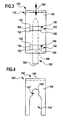
- a second embodiment of a holding device 100 shown in FIG. 4 differs from the first embodiment described above only in that the contact leg 140 of the first bracket 142 not with a single passage opening 144 with a closed edge, but instead with a large passage opening 144 'and a smaller one Passage opening 144 "is provided, none of these passage openings has a closed edge, but the larger passage opening 144 'at the front edge of the contact leg 140 and the smaller opening 144 "at its front end into the larger one Passage opening 144 'opens.
- the holding device 100 is arranged so that the connecting pipe 126 through the am best fitting passage opening 144 ', 144 ".
Landscapes
- Engineering & Computer Science (AREA)
- Health & Medical Sciences (AREA)
- Life Sciences & Earth Sciences (AREA)
- Hydrology & Water Resources (AREA)
- Public Health (AREA)
- Water Supply & Treatment (AREA)
- Environmental & Geological Engineering (AREA)
- Domestic Plumbing Installations (AREA)
- Sink And Installation For Waste Water (AREA)
- Supports Or Holders For Household Use (AREA)
- Jigs For Machine Tools (AREA)
- Workshop Equipment, Work Benches, Supports, Or Storage Means (AREA)
- Manipulator (AREA)
Abstract
Description
- Fig. 1
- eine schematische Seitenansicht des unteren Bereichs einer Armatur, die mittels einer Haltevorrichtung an einer Arbeitsplatte gehalten ist;
- Fig. 2
- eine perspektivische Darstellung der Haltevorrichtung aus Fig. 1;
- Fig. 3
- eine schematische Vorderansicht der Haltevorrichtung aus Fig. 2, mit Blickrichtung in Richtung des Pfeiles 3 in Fig. 2; und
- Fig. 4
- eine schematische Draufsicht auf einen horizontalen Halteschenkel eines armaturenseitigen Haltewinkels einer zweiten Ausführungsform der Haltevorrichtung.
Claims (15)
- Haltevorrichtung zum Haltern einer Armatur (102) an einer Spüle (104), die an einer Arbeitsplatte (106) angeordnet ist, wobei die Haltevorrichtung ein erstes Halteelement (142), das an der Armatur (102) festlegbar ist, und ein zweites Halteelement (160), das an der Arbeitsplatte (106) festlegbar ist, umfaßt, wobei das erste Halteelement (142) und das zweite Halteelement (160) so miteinander verbindbar sind, daß Kräfte von dem ersten Halteelement (142) auf das zweite Halteelement (160) übertragbar sind.
- Haltevorrichtung nach Anspruch 1, dadurch gekennzeichnet, daß das erste Halteelement (142) winkelförmig ausgebildet ist.
- Haltevorrichtung nach einem der Ansprüche 1 oder 2, dadurch gekennzeichnet, daß das zweite Halteelement (160) winkelförmig ausgebildet ist.
- Haltevorrichtung nach einem der Ansprüche 1 bis 3, dadurch gekennzeichnet, daß das erste Halteelement (142) mindestens eine Durchtrittsöffnung (144; 144', 144") für die Armatur (102) aufweist.
- Haltevorrichtung nach Anspruch 4, dadurch gekennzeichnet, daß die Durchtrittsöffnung (144) einen geschlossenen Rand (146) aufweist.
- Haltevorrichtung nach einem der Ansprüche 1 bis 5, dadurch gekennzeichnet, daß das erste Halteelement (142) mindestens zwei Durchtrittsöffnungen (144', 144") für die Armatur (102) aufweist.
- Haltevorrichtung nach Anspruch 6, dadurch gekennzeichnet, daß das erste Halteelement (142) mindestens zwei Durchtrittsöffnungen (144', 144") unterschiedlicher Größe aufweist.
- Haltevorrichtung nach einem der Ansprüche 1 bis 7, dadurch gekennzeichnet, daß die Haltevorrichtung (100) eine Führung (162) umfaßt, mittels welcher eines der Halteelemente (160) längs einer Verschiebungsrichtung (164) verschieblich an dem jeweils anderen Halteelement (142) geführt ist.
- Haltevorrichtung nach Anspruch 8, dadurch gekennzeichnet, daß die Führung (162) mindestens eine Führungslasche (150) umfaßt, welche das geführte Halteelement (160) umgreift.
- Haltevorrichtung nach Anspruch 9, dadurch gekennzeichnet, daß die Führung (162) mindestens zwei längs der Verschiebungsrichtung (164) voneinander beabstandete Führungslaschen (150) umfaßt, welche das geführte Halteelement (160) umgreifen.
- Haltevorrichtung nach einem der Ansprüche 8 bis 10, dadurch gekennzeichnet, daß die Verschiebungsrichtung (164) im montierten Zustand der Haltevorrichtung (100) im wesentlichen vertikal gerichtet ist.
- Haltevorrichtung nach einem der Ansprüche 1 bis 11, dadurch gekennzeichnet, daß das zweite Halteelement (160) eine Anlagefläche (168) umfaßt, mit welcher das zweite Halteelement (160) im montierten Zustand der Haltevorrichtung (100) an der Arbeitsplatte (106) anliegt.
- Haltevorrichtung nach einem der Ansprüche 1 bis 12, dadurch gekennzeichnet, daß die Haltevorrichtung (100) mindestens ein Befestigungsmittel (174) zum Festlegen des zweiten Halteelements (160) an der Arbeitsplatte (106) umfaßt.
- Armatur für eine Spüle (104), die an einer Arbeitsplatte (106) angeordnet ist, umfassend eine Haltevorrichtung (100) zum Haltern der Armatur (102) an der Spüle (104) nach einem der Ansprüche 1 bis 13.
- Spüle zum Anordnen an einer Arbeitsplatte (106), umfassend eine Armatur (102) mit einer Haltevorrichtung (100) zum Haltern der Armatur (102) an der Spüle (104) nach einem der Ansprüche 1 bis 13.
Applications Claiming Priority (2)
| Application Number | Priority Date | Filing Date | Title |
|---|---|---|---|
| DE10251568 | 2002-11-06 | ||
| DE10251568A DE10251568A1 (de) | 2002-11-06 | 2002-11-06 | Haltevorrichtung zum Haltern einer Armatur an einer Spüle, die an einer Arbeitsplatte angeordnet ist |
Publications (3)
| Publication Number | Publication Date |
|---|---|
| EP1418281A2 true EP1418281A2 (de) | 2004-05-12 |
| EP1418281A3 EP1418281A3 (de) | 2004-12-01 |
| EP1418281B1 EP1418281B1 (de) | 2008-12-24 |
Family
ID=32103361
Family Applications (1)
| Application Number | Title | Priority Date | Filing Date |
|---|---|---|---|
| EP03025062A Expired - Lifetime EP1418281B1 (de) | 2002-11-06 | 2003-10-31 | Haltevorrichtung zum Haltern einer Armatur an einer Spüle, die an einer Arbeitsplatte angeordnet ist |
Country Status (5)
| Country | Link |
|---|---|
| EP (1) | EP1418281B1 (de) |
| AT (1) | ATE418650T1 (de) |
| DE (2) | DE10251568A1 (de) |
| DK (1) | DK1418281T3 (de) |
| ES (1) | ES2316687T3 (de) |
Cited By (2)
| Publication number | Priority date | Publication date | Assignee | Title |
|---|---|---|---|---|
| EP2080838A3 (de) * | 2008-01-18 | 2015-01-21 | Franke Technology and Trademark Ltd | Befestigungsvorrichtung zum Fixieren einer Armatur an einer von einem Möbel getragenen Spüle |
| WO2020007633A1 (de) * | 2018-07-05 | 2020-01-09 | Franke Technology And Trademark Ltd | Armaturenverstärkung für eine spüle und verfahren zum abstützen einer armatur bei einer spüle |
Families Citing this family (1)
| Publication number | Priority date | Publication date | Assignee | Title |
|---|---|---|---|---|
| DE102021207776A1 (de) | 2021-07-21 | 2023-01-26 | BSH Hausgeräte GmbH | Anordnung mit einem Spülbecken und einem Wasserhahn sowie mit einer spezifischen Verspannvorrichtung, sowie Verfahren |
Family Cites Families (7)
| Publication number | Priority date | Publication date | Assignee | Title |
|---|---|---|---|---|
| DE8810505U1 (de) * | 1988-08-19 | 1989-02-23 | BTS-Bau-Installations-Systeme GmbH, 8755 Alzenau | Vorrichtung zur Halterung von Anschlußdosen für Kalt- und Warmwasserarmaturen |
| US5135022A (en) * | 1991-01-17 | 1992-08-04 | Masco Corporation Of Indiana | Vertically adjustable valve fitting assembly for tubs |
| US5143121A (en) * | 1991-11-08 | 1992-09-01 | Kohler Co. | Fluid pulse generating apparatus |
| DE4431869A1 (de) * | 1994-09-07 | 1996-03-14 | Knebel & Roettger Fa | Vorrichtung zur Befestigung einer Armatur an einer Arbeitsplatte, Spüle oder dergleichen |
| DE4443668C2 (de) * | 1994-12-08 | 2000-03-30 | Grohe Armaturen Friedrich | Auslaufarmatur mit Befestigungseinrichtung |
| DE19860186A1 (de) * | 1998-06-29 | 1999-12-30 | Aquis Gmbh Rebstein | Spülvorrichtung mit Spülbecken |
| GB9924080D0 (en) * | 1999-10-13 | 1999-12-15 | Springfast Ltd | Improvements relating to fasteners |
-
2002
- 2002-11-06 DE DE10251568A patent/DE10251568A1/de not_active Withdrawn
-
2003
- 2003-10-31 DE DE50310968T patent/DE50310968D1/de not_active Expired - Lifetime
- 2003-10-31 AT AT03025062T patent/ATE418650T1/de active
- 2003-10-31 EP EP03025062A patent/EP1418281B1/de not_active Expired - Lifetime
- 2003-10-31 DK DK03025062T patent/DK1418281T3/da active
- 2003-10-31 ES ES03025062T patent/ES2316687T3/es not_active Expired - Lifetime
Cited By (2)
| Publication number | Priority date | Publication date | Assignee | Title |
|---|---|---|---|---|
| EP2080838A3 (de) * | 2008-01-18 | 2015-01-21 | Franke Technology and Trademark Ltd | Befestigungsvorrichtung zum Fixieren einer Armatur an einer von einem Möbel getragenen Spüle |
| WO2020007633A1 (de) * | 2018-07-05 | 2020-01-09 | Franke Technology And Trademark Ltd | Armaturenverstärkung für eine spüle und verfahren zum abstützen einer armatur bei einer spüle |
Also Published As
| Publication number | Publication date |
|---|---|
| DK1418281T3 (da) | 2009-03-30 |
| ES2316687T3 (es) | 2009-04-16 |
| DE10251568A1 (de) | 2004-05-27 |
| EP1418281B1 (de) | 2008-12-24 |
| EP1418281A3 (de) | 2004-12-01 |
| ATE418650T1 (de) | 2009-01-15 |
| DE50310968D1 (de) | 2009-02-05 |
Similar Documents
| Publication | Publication Date | Title |
|---|---|---|
| DE69514385T2 (de) | Oberseitig montierte wannenbatterie | |
| DE112017000156B4 (de) | Ein Überlochinstallationsgerät | |
| AT13849U1 (de) | Befestigungsanordnung für einen Wasserhahn | |
| DE202007005020U1 (de) | Mehrzweck-Stützgestell | |
| DE8322502U1 (de) | Vorrichtung zur Befestigung eines Rohrs auf einer Unterlage | |
| EP1418282B1 (de) | Haltevorrichtung zum Haltern einer Armatur an einer Spüle, die an einer Arbeitsplatte angeordnet ist | |
| EP1418281A2 (de) | Haltevorrichtung zum Haltern einer Armatur an einer Spüle, die an einer Arbeitsplatte angeordnet ist | |
| DE2910144A1 (de) | Vorrichtung zum sammeln von abfaellen | |
| DE202021104030U1 (de) | Befestigungsvorrichtung für Wasserhähne | |
| WO2014037413A1 (de) | Ablaufgarnitur und verfahren zum anordnen einer ablaufgarnitur an einem ablaufflansch eines beckens | |
| DE102005046861B4 (de) | Befestigungsvorrichtung für Armaturen von Küchenspülen | |
| AT393883B (de) | Anschlussbogen | |
| DE102004036634B4 (de) | Vorrichtung zum Begasen von Flüssigkeiten und Verfahren zur Montage der Vorrichtung | |
| DE29819469U1 (de) | Befestigungsvorrichtung für Toilettenbrillen und/oder -deckel | |
| AT408107B (de) | Vorrichtung zum befestigen eines kalt- und eines warmwasseranschlusses an einer blendwand | |
| DE3604932A1 (de) | Mehrfachanschluss-armatur fuer eine anschlussdose fuer brauchwasser-installationen | |
| DE10016504A1 (de) | Befestigungsvorrichtung für eine Armatur auf ihrer Unterlage | |
| DE9403872U1 (de) | Rohrschelle | |
| EP2080838A2 (de) | Befestigungsvorrichtung zum Fixieren einer Armatur an einer von einem Möbel getragenen Spüle | |
| DE29904139U1 (de) | Ablaufgarnitur für eine Badewanne | |
| DE10114358A1 (de) | Sanitärarmatur | |
| DE19650971A1 (de) | Rohrförmiges Ausgleichsstück | |
| AT409645B (de) | Vorrichtung zum befestigen eines abwasserrohres an einer montageschiene | |
| DE102005037200A1 (de) | Rohrschelle | |
| DE10012504A1 (de) | Verfahren und Vorrichtung für die Befestigung einer Armatur auf ihrer Unterlage |
Legal Events
| Date | Code | Title | Description |
|---|---|---|---|
| PUAI | Public reference made under article 153(3) epc to a published international application that has entered the european phase |
Free format text: ORIGINAL CODE: 0009012 |
|
| AK | Designated contracting states |
Kind code of ref document: A2 Designated state(s): AT BE BG CH CY CZ DE DK EE ES FI FR GB GR HU IE IT LI LU MC NL PT RO SE SI SK TR |
|
| AX | Request for extension of the european patent |
Extension state: AL LT LV MK |
|
| PUAL | Search report despatched |
Free format text: ORIGINAL CODE: 0009013 |
|
| AK | Designated contracting states |
Kind code of ref document: A3 Designated state(s): AT BE BG CH CY CZ DE DK EE ES FI FR GB GR HU IE IT LI LU MC NL PT RO SE SI SK TR |
|
| AX | Request for extension of the european patent |
Extension state: AL LT LV MK |
|
| 17P | Request for examination filed |
Effective date: 20050409 |
|
| AKX | Designation fees paid |
Designated state(s): AT BE BG CH CY CZ DE DK EE ES FI FR GB GR HU IE IT LI LU MC NL PT RO SE SI SK TR |
|
| 17Q | First examination report despatched |
Effective date: 20060515 |
|
| GRAP | Despatch of communication of intention to grant a patent |
Free format text: ORIGINAL CODE: EPIDOSNIGR1 |
|
| GRAS | Grant fee paid |
Free format text: ORIGINAL CODE: EPIDOSNIGR3 |
|
| GRAA | (expected) grant |
Free format text: ORIGINAL CODE: 0009210 |
|
| AK | Designated contracting states |
Kind code of ref document: B1 Designated state(s): AT BE BG CH CY CZ DE DK EE ES FI FR GB GR HU IE IT LI LU MC NL PT RO SE SI SK TR |
|
| REG | Reference to a national code |
Ref country code: GB Ref legal event code: FG4D Free format text: NOT ENGLISH |
|
| REG | Reference to a national code |
Ref country code: CH Ref legal event code: NV Representative=s name: ISLER & PEDRAZZINI AG Ref country code: CH Ref legal event code: EP |
|
| REG | Reference to a national code |
Ref country code: IE Ref legal event code: FG4D Free format text: LANGUAGE OF EP DOCUMENT: GERMAN |
|
| REF | Corresponds to: |
Ref document number: 50310968 Country of ref document: DE Date of ref document: 20090205 Kind code of ref document: P |
|
| REG | Reference to a national code |
Ref country code: DK Ref legal event code: T3 |
|
| REG | Reference to a national code |
Ref country code: ES Ref legal event code: FG2A Ref document number: 2316687 Country of ref document: ES Kind code of ref document: T3 |
|
| PG25 | Lapsed in a contracting state [announced via postgrant information from national office to epo] |
Ref country code: NL Free format text: LAPSE BECAUSE OF FAILURE TO SUBMIT A TRANSLATION OF THE DESCRIPTION OR TO PAY THE FEE WITHIN THE PRESCRIBED TIME-LIMIT Effective date: 20081224 Ref country code: FI Free format text: LAPSE BECAUSE OF FAILURE TO SUBMIT A TRANSLATION OF THE DESCRIPTION OR TO PAY THE FEE WITHIN THE PRESCRIBED TIME-LIMIT Effective date: 20081224 Ref country code: SI Free format text: LAPSE BECAUSE OF FAILURE TO SUBMIT A TRANSLATION OF THE DESCRIPTION OR TO PAY THE FEE WITHIN THE PRESCRIBED TIME-LIMIT Effective date: 20081224 |
|
| NLV1 | Nl: lapsed or annulled due to failure to fulfill the requirements of art. 29p and 29m of the patents act | ||
| REG | Reference to a national code |
Ref country code: IE Ref legal event code: FD4D |
|
| PG25 | Lapsed in a contracting state [announced via postgrant information from national office to epo] |
Ref country code: RO Free format text: LAPSE BECAUSE OF FAILURE TO SUBMIT A TRANSLATION OF THE DESCRIPTION OR TO PAY THE FEE WITHIN THE PRESCRIBED TIME-LIMIT Effective date: 20081224 Ref country code: EE Free format text: LAPSE BECAUSE OF FAILURE TO SUBMIT A TRANSLATION OF THE DESCRIPTION OR TO PAY THE FEE WITHIN THE PRESCRIBED TIME-LIMIT Effective date: 20081224 Ref country code: BG Free format text: LAPSE BECAUSE OF FAILURE TO SUBMIT A TRANSLATION OF THE DESCRIPTION OR TO PAY THE FEE WITHIN THE PRESCRIBED TIME-LIMIT Effective date: 20090324 Ref country code: IE Free format text: LAPSE BECAUSE OF FAILURE TO SUBMIT A TRANSLATION OF THE DESCRIPTION OR TO PAY THE FEE WITHIN THE PRESCRIBED TIME-LIMIT Effective date: 20081224 |
|
| PG25 | Lapsed in a contracting state [announced via postgrant information from national office to epo] |
Ref country code: PT Free format text: LAPSE BECAUSE OF FAILURE TO SUBMIT A TRANSLATION OF THE DESCRIPTION OR TO PAY THE FEE WITHIN THE PRESCRIBED TIME-LIMIT Effective date: 20090525 Ref country code: SE Free format text: LAPSE BECAUSE OF FAILURE TO SUBMIT A TRANSLATION OF THE DESCRIPTION OR TO PAY THE FEE WITHIN THE PRESCRIBED TIME-LIMIT Effective date: 20090324 |
|
| PG25 | Lapsed in a contracting state [announced via postgrant information from national office to epo] |
Ref country code: SK Free format text: LAPSE BECAUSE OF FAILURE TO SUBMIT A TRANSLATION OF THE DESCRIPTION OR TO PAY THE FEE WITHIN THE PRESCRIBED TIME-LIMIT Effective date: 20081224 |
|
| PLBE | No opposition filed within time limit |
Free format text: ORIGINAL CODE: 0009261 |
|
| STAA | Information on the status of an ep patent application or granted ep patent |
Free format text: STATUS: NO OPPOSITION FILED WITHIN TIME LIMIT |
|
| 26N | No opposition filed |
Effective date: 20090925 |
|
| PG25 | Lapsed in a contracting state [announced via postgrant information from national office to epo] |
Ref country code: MC Free format text: LAPSE BECAUSE OF NON-PAYMENT OF DUE FEES Effective date: 20091031 |
|
| PG25 | Lapsed in a contracting state [announced via postgrant information from national office to epo] |
Ref country code: GR Free format text: LAPSE BECAUSE OF FAILURE TO SUBMIT A TRANSLATION OF THE DESCRIPTION OR TO PAY THE FEE WITHIN THE PRESCRIBED TIME-LIMIT Effective date: 20090325 |
|
| PGFP | Annual fee paid to national office [announced via postgrant information from national office to epo] |
Ref country code: AT Payment date: 20101014 Year of fee payment: 8 |
|
| PGFP | Annual fee paid to national office [announced via postgrant information from national office to epo] |
Ref country code: DE Payment date: 20101127 Year of fee payment: 8 |
|
| PGFP | Annual fee paid to national office [announced via postgrant information from national office to epo] |
Ref country code: IT Payment date: 20101022 Year of fee payment: 8 Ref country code: GB Payment date: 20101027 Year of fee payment: 8 |
|
| PG25 | Lapsed in a contracting state [announced via postgrant information from national office to epo] |
Ref country code: LU Free format text: LAPSE BECAUSE OF NON-PAYMENT OF DUE FEES Effective date: 20091031 |
|
| PG25 | Lapsed in a contracting state [announced via postgrant information from national office to epo] |
Ref country code: HU Free format text: LAPSE BECAUSE OF FAILURE TO SUBMIT A TRANSLATION OF THE DESCRIPTION OR TO PAY THE FEE WITHIN THE PRESCRIBED TIME-LIMIT Effective date: 20090625 |
|
| PG25 | Lapsed in a contracting state [announced via postgrant information from national office to epo] |
Ref country code: TR Free format text: LAPSE BECAUSE OF FAILURE TO SUBMIT A TRANSLATION OF THE DESCRIPTION OR TO PAY THE FEE WITHIN THE PRESCRIBED TIME-LIMIT Effective date: 20081224 |
|
| PG25 | Lapsed in a contracting state [announced via postgrant information from national office to epo] |
Ref country code: CY Free format text: LAPSE BECAUSE OF FAILURE TO SUBMIT A TRANSLATION OF THE DESCRIPTION OR TO PAY THE FEE WITHIN THE PRESCRIBED TIME-LIMIT Effective date: 20081224 |
|
| PGFP | Annual fee paid to national office [announced via postgrant information from national office to epo] |
Ref country code: CZ Payment date: 20110929 Year of fee payment: 9 |
|
| PGFP | Annual fee paid to national office [announced via postgrant information from national office to epo] |
Ref country code: CH Payment date: 20111012 Year of fee payment: 9 Ref country code: BE Payment date: 20111012 Year of fee payment: 9 Ref country code: DK Payment date: 20111011 Year of fee payment: 9 Ref country code: FR Payment date: 20111103 Year of fee payment: 9 Ref country code: ES Payment date: 20111115 Year of fee payment: 9 |
|
| BERE | Be: lapsed |
Owner name: BLANCO G.M.B.H. + CO KG Effective date: 20121031 |
|
| REG | Reference to a national code |
Ref country code: CH Ref legal event code: PL |
|
| REG | Reference to a national code |
Ref country code: DK Ref legal event code: EBP |
|
| REG | Reference to a national code |
Ref country code: AT Ref legal event code: MM01 Ref document number: 418650 Country of ref document: AT Kind code of ref document: T Effective date: 20121031 |
|
| GBPC | Gb: european patent ceased through non-payment of renewal fee |
Effective date: 20121031 |
|
| REG | Reference to a national code |
Ref country code: FR Ref legal event code: ST Effective date: 20130628 |
|
| PG25 | Lapsed in a contracting state [announced via postgrant information from national office to epo] |
Ref country code: BE Free format text: LAPSE BECAUSE OF NON-PAYMENT OF DUE FEES Effective date: 20121031 Ref country code: CH Free format text: LAPSE BECAUSE OF NON-PAYMENT OF DUE FEES Effective date: 20121031 Ref country code: LI Free format text: LAPSE BECAUSE OF NON-PAYMENT OF DUE FEES Effective date: 20121031 Ref country code: GB Free format text: LAPSE BECAUSE OF NON-PAYMENT OF DUE FEES Effective date: 20121031 Ref country code: AT Free format text: LAPSE BECAUSE OF NON-PAYMENT OF DUE FEES Effective date: 20121031 Ref country code: DE Free format text: LAPSE BECAUSE OF NON-PAYMENT OF DUE FEES Effective date: 20130501 Ref country code: CZ Free format text: LAPSE BECAUSE OF NON-PAYMENT OF DUE FEES Effective date: 20121031 |
|
| REG | Reference to a national code |
Ref country code: DE Ref legal event code: R119 Ref document number: 50310968 Country of ref document: DE Effective date: 20130501 |
|
| PG25 | Lapsed in a contracting state [announced via postgrant information from national office to epo] |
Ref country code: FR Free format text: LAPSE BECAUSE OF NON-PAYMENT OF DUE FEES Effective date: 20121031 Ref country code: IT Free format text: LAPSE BECAUSE OF NON-PAYMENT OF DUE FEES Effective date: 20121031 |
|
| PG25 | Lapsed in a contracting state [announced via postgrant information from national office to epo] |
Ref country code: DK Free format text: LAPSE BECAUSE OF NON-PAYMENT OF DUE FEES Effective date: 20121031 |
|
| REG | Reference to a national code |
Ref country code: ES Ref legal event code: FD2A Effective date: 20140207 |
|
| PG25 | Lapsed in a contracting state [announced via postgrant information from national office to epo] |
Ref country code: ES Free format text: LAPSE BECAUSE OF NON-PAYMENT OF DUE FEES Effective date: 20121101 |