EP1418281B1 - Haltevorrichtung zum Haltern einer Armatur an einer Spüle, die an einer Arbeitsplatte angeordnet ist - Google Patents
Haltevorrichtung zum Haltern einer Armatur an einer Spüle, die an einer Arbeitsplatte angeordnet ist Download PDFInfo
- Publication number
- EP1418281B1 EP1418281B1 EP03025062A EP03025062A EP1418281B1 EP 1418281 B1 EP1418281 B1 EP 1418281B1 EP 03025062 A EP03025062 A EP 03025062A EP 03025062 A EP03025062 A EP 03025062A EP 1418281 B1 EP1418281 B1 EP 1418281B1
- Authority
- EP
- European Patent Office
- Prior art keywords
- retaining
- fitting
- retaining device
- worktop
- sink
- Prior art date
- Legal status (The legal status is an assumption and is not a legal conclusion. Google has not performed a legal analysis and makes no representation as to the accuracy of the status listed.)
- Expired - Lifetime
Links
- 238000006073 displacement reaction Methods 0.000 claims description 7
- 239000000853 adhesive Substances 0.000 description 2
- 230000001070 adhesive effect Effects 0.000 description 2
- 238000004026 adhesive bonding Methods 0.000 description 1
- 230000005540 biological transmission Effects 0.000 description 1
- 230000002349 favourable effect Effects 0.000 description 1
- 238000003780 insertion Methods 0.000 description 1
- 230000037431 insertion Effects 0.000 description 1
- 239000000463 material Substances 0.000 description 1
- 238000000034 method Methods 0.000 description 1
- 229920001296 polysiloxane Polymers 0.000 description 1
- 239000000565 sealant Substances 0.000 description 1
- 229910001220 stainless steel Inorganic materials 0.000 description 1
- 239000010935 stainless steel Substances 0.000 description 1
- XLYOFNOQVPJJNP-UHFFFAOYSA-N water Substances O XLYOFNOQVPJJNP-UHFFFAOYSA-N 0.000 description 1
- 239000002023 wood Substances 0.000 description 1
Images

Classifications
-
- E—FIXED CONSTRUCTIONS
- E03—WATER SUPPLY; SEWERAGE
- E03C—DOMESTIC PLUMBING INSTALLATIONS FOR FRESH WATER OR WASTE WATER; SINKS
- E03C1/00—Domestic plumbing installations for fresh water or waste water; Sinks
- E03C1/12—Plumbing installations for waste water; Basins or fountains connected thereto; Sinks
- E03C1/32—Holders or supports for basins
- E03C1/33—Fastening sinks or basins in an apertured support
-
- E—FIXED CONSTRUCTIONS
- E03—WATER SUPPLY; SEWERAGE
- E03C—DOMESTIC PLUMBING INSTALLATIONS FOR FRESH WATER OR WASTE WATER; SINKS
- E03C1/00—Domestic plumbing installations for fresh water or waste water; Sinks
- E03C1/02—Plumbing installations for fresh water
- E03C1/04—Water-basin installations specially adapted to wash-basins or baths
- E03C1/0401—Fixing a tap to the sanitary appliance or to an associated mounting surface, e.g. a countertop
Definitions
- a fitting such as a faucet
- a sink is made of a relatively thin material, such as a stainless steel sheet.
- a relatively unstable fixation of the valve to the sink can be achieved.
- the GB-A-2 355 284 discloses a holding device for securing a sink to a worktop.
- the present invention has for its object to provide a way to stably support a fitting to a sink, which is arranged on a worktop.
- first retaining element and the second retaining element can be connected to one another in such a way that forces in the horizontal direction can be transmitted from the first retaining element to the second retaining element.
- the first holding element and / or the second holding element is formed angularly.
- the fitting-side first retaining element has at least one passage opening for the fitting.
- This passage opening may have an open edge or a closed edge.
- a versatility of the holding device is achieved when the first holding element has at least two passage openings for a valve.
- the holding device can be used with fittings having different thickness connection tubes, wherein the holding device is always arranged so that the connection pipe of the fitting passes through the best fitting passage opening.
- the at least two passage openings of the first holding element may in particular be of different sizes.
- the holding device comprises a guide, by means of which one of the holding elements along a direction of displacement is displaceably guided on the respective other holding element.
- Such a guide may in particular comprise at least one guide tab which engages around the guided holding element.
- a particularly effective transmission of forces and torques between the two holding elements is ensured when the guide comprises at least two along the direction of displacement spaced guide tabs which engage around the guided holding element.
- the displacement direction of the guide is directed in the mounted state of the holding device substantially vertically.
- the guided holding element can be the fitting-side first holding element or the worktop-side second holding element.
- the second holding element comprises a contact surface, with which the second holding element rests in the mounted state of the holding device on the worktop.
- the holding device comprises at least one fastening means for fixing the second holding element to the worktop.
- Such a fastening means may for example be a screw which is screwed into the worktop.
- the contact surface of the second holding element is glued by means of a suitable adhesive with an opposing contact surface of the worktop.
- fitting-side first retaining element and the work-plate-side second retaining element need not be in direct contact with each other; Rather, it is conceivable that at least one further retaining element is provided which establishes the mechanical connection between the first retaining element and the second retaining element for transmitting forces from the first retaining element to the second retaining element.
- Claim 14 is directed to a sink for placement on a worktop, which comprises a fitting with a holding device according to the invention for holding the fitting to the sink.
- valve 102 which may be formed, for example, as a mixer tap, to a sink 104, which is inserted into a receiving opening 108 in a worktop 106.
- the fitting support surface 118 drops over a slope 120 facing away from the rinse edge 110 to a horizontal rinsing surface 122 out in which the or the basin of the sink 104 are arranged.
- These guide plates 150 are formed by the fact that in each case two horizontal cuts are produced in the guide leg 148 and the web 154 is bent out of the plane of the guide leg 148 between each two cuts to the side facing away from the plant leg 140 side of the guide leg 148, so that in the Guide legs 148 each have a through opening 156 is formed.
- a vertical guide leg 158 of a second bracket 160 extends between the guide plates 150 and the respective associated passage opening 156 therethrough, so that the guide plates 150 together form a guide 162, by means of which the guide leg 158 of the second bracket 160 along a vertical displacement direction 164 slidably guided on the guide leg 148 of the first bracket 142.
- the first bracket 142 facing the front of the guide leg 158 lies flat against the back of the guide leg 148 of the first retaining angle 142, while the first bracket 142 facing away from the back of the guide leg 158 rests against the guide plates 150 substantially free of play.
- the guide leg 158 of the second bracket 160 tapers towards its upper end to facilitate insertion of the guide leg 158 into the guide tabs 150 of the first bracket 152.
- the second bracket 160 further includes a mounted in the state of the holding device 100 horizontally aligned bearing leg 166, the top 168 rests flat against the bottom 170 of the countertop 106.
- the top 168 of the abutment leg 166 is adhesively bonded by means of a suitable adhesive to the bottom 170 of the countertop 106.
- a seal 176 made of a resilient plastic sealant such as silicone , intended.
- the connecting pipe 126 of the valve 102 is passed from above through the through hole 124 in the Armaturentrage materials 118 of the sink 104 until the fitting body 128 abuts the top of the Armaturentrage materials 118.
- the first bracket 142 of the holding device 100 is attached to the connecting pipe 126 so that the connecting pipe 126 passes through the passage opening 144 in the plant leg 140.
- the first bracket 142 is fixed by tightening the fixing nut 136.
- the second bracket 160 with the guide leg 158 is inserted from below into the guide tabs 150 of the guide leg 148 of the first bracket 142 until the top 168 of the support leg 166 of the second bracket 160 rests against the bottom 170 of the countertop 106.
- the abutment leg 166 of the second bracket 160 is fixed by gluing and / or screwing to the work surface 106, whereby the assembly of the holding device 100 is completed.
- valve 102 In this way, a stable fixation of the valve 102 is ensured, which is sufficient for particularly heavy valves 102, for example, provided with hose showers faucets.
- FIG. 4 illustrated second embodiment of a holding device 100 differs from the first embodiment described above only in that the abutment leg 140 of the first bracket 142 not with a single passage opening 144 with a closed edge, but instead with a large passage opening 144 'and a smaller passage opening 144 " is provided, wherein none of these passage openings has a closed edge, but the larger passage opening 144 'at the front edge of the support leg 140 opens and the smaller passage opening 144 "at its front end into the larger passage opening 144 'opens.
- the second embodiment of a holding device 100 is identical in structure and function with the first embodiment, the above description of which reference is made in this regard.
Landscapes
- Engineering & Computer Science (AREA)
- Health & Medical Sciences (AREA)
- Life Sciences & Earth Sciences (AREA)
- Hydrology & Water Resources (AREA)
- Public Health (AREA)
- Water Supply & Treatment (AREA)
- Environmental & Geological Engineering (AREA)
- Domestic Plumbing Installations (AREA)
- Supports Or Holders For Household Use (AREA)
- Sink And Installation For Waste Water (AREA)
- Workshop Equipment, Work Benches, Supports, Or Storage Means (AREA)
- Jigs For Machine Tools (AREA)
- Manipulator (AREA)
Description
- Die Montage einer Armatur, beispielsweise einer Mischbatterie, an einer Spüle kann Probleme aufwerfen, insbesondere dann, wenn die Armatur schwer ist und die Spüle aus einem relativ dünnen Material, beispielsweise aus einem Edelstahlblech, hergestellt ist. In solchen Fällen kann häufig nur eine vergleichsweise labile Fixierung der Armatur an der Spüle erzielt werden.
- Die
GB-A-2 355 284 - Der vorliegenden Erfindung liegt die Aufgabe zugrunde, eine Möglichkeit zu schaffen, eine Armatur stabil an einer Spüle zu haltern, die an einer Arbeitsplatte angeordnet ist.
- Diese Aufgabe wird erfindungsgemäß durch eine Haltevorrichtung nach Anspruch 1 gelöst.
- Auf diese Weise können auf die Armatur einwirkende Kräfte über die Haltevorrichtung direkt von der Arbeitsplatte aufgenommen werden, ohne dass die an der Arbeitsplatte angeordnete Spüle beansprucht wird.
- Hierdurch ist eine stabile Fixierung der Armatur an der Spüle gewährleistet, welche auch für besonders schwere Armaturen, beispielsweise für mit Schlauchbrausen versehene Mischbatterien, ausreichend ist.
- Besonders günstig ist es, wenn das erste Halteelement und das zweite Halteelement so miteinander verbindbar sind, dass Kräfte in horizontaler Richtung von dem ersten Halteelement auf das zweite Halteelement übertragbar sind.
- Bei bevorzugten Ausgestaltungen der erfindungsgemäßen Haltevorrichtung ist das erste Halteelement und/oder das zweite Halteelement winkelförmig ausgebildet.
- Das armaturenseitige erste Halteelement weist mindestens eine Durchtrittsöffnung für die Armatur auf.
- Diese Durchtrittsöffnung kann einen offenen Rand oder einen geschlossenen Rand aufweisen.
- Eine vielseitige Verwendbarkeit der Haltevorrichtung wird erreicht, wenn das erste Halteelement mindestens zwei Durchtrittsöffnungen für eine Armatur aufweist. In diesem Fall kann die Haltevorrichtung mit Armaturen verwendet werden, die unterschiedlich dicke Anschlussrohre aufweisen, wobei die Haltevorrichtung stets so angeordnet wird, dass das Anschlussrohr der Armatur durch die am besten passende Durchtrittsöffnung hindurchtritt.
- Die mindestens zwei Durchtrittsöffnungen des ersten Halteelements können insbesondere von unterschiedlicher Größe sein.
- Um die Verbindung der Armatur über die Haltevorrichtung mit Arbeitsplatten unterschiedlicher Dicke herstellen zu können, ist es günstig, wenn die Haltevorrichtung eine Führung umfaßt, mittels welcher eines der Halteelemente längs einer Verschiebungsrichtung verschieblich an dem jeweils anderen Halteelement geführt ist.
- Eine solche Führung kann insbesondere mindestens eine Führungslasche umfassen, welche das geführte Halteelement umgreift.
- Eine besonders wirksame Übertragung von Kräften und Drehmomenten zwischen den beiden Halteelementen ist gewährleistet, wenn die Führung mindestens zwei längs der Verschiebungsrichtung voneinander beabstandete Führungslaschen umfaßt, welche das geführte Halteelement umgreifen.
- Da die Arbeitsplatte im montierten Zustand üblicherweise horizontal ausgerichtet ist, ist es günstig, wenn die Verschiebungsrichtung der Führung im montierten Zustand der Haltevorrichtung im wesentlichen vertikal gerichtet ist.
- Das geführte Halteelement kann dabei das armaturenseitige erste Halteelement oder das arbeitsplattenseitige zweite Halteelement sein.
- Um eine wirksame Übertragung von Kräften und Drehmomenten von der Haltevorrichtung auf die Arbeitsplatte zu ermöglichen, ist vorteilhafterweise vorgesehen, daß das zweite Halteelement eine Anlagefläche umfaßt, mit welcher das zweite Halteelement im montierten Zustand der Haltevorrichtung an der Arbeitsplatte anliegt.
- Für die Festlegung des zweiten Halteelements an der Arbeitsplatte gibt es verschiedene Möglichkeiten.
- So kann beispielsweise vorgesehen sein, dass die Haltevorrichtung mindestens ein Befestigungsmittel zum Festlegen des zweiten Halteelements an der Arbeitsplatte umfasst.
- Ein solches Befestigungsmittel kann beispielsweise eine Schraube sein, welche in die Arbeitsplatte eingedreht wird.
- Alternativ oder ergänzend hierzu kann auch vorgesehen sein, dass die Anlagefläche des zweiten Halteelements mittels eines geeigneten Klebemittels mit einer gegenüberliegenden Anlagefläche der Arbeitsplatte verklebt ist.
- Die Haltevorrichtung muss nicht notwendigerweise zweiteilig ausgebildet sein; vielmehr kann die erfindungsgemäße Haltevorrichtung außer dem armaturenseitigen ersten Halteelement und dem arbeitsplattenseitigen zweiten Halteelement noch weitere Elemente umfassen.
- Insbesondere müssen das armaturenseitige erste Halteelement und das arbeitsplattenseitige zweite Halteelement nicht unmittelbar miteinander in Kontakt stehen; vielmehr ist es denkbar, dass mindestens ein weiteres Halteelement vorgesehen ist, welches die mechanische Verbindung zwischen dem ersten Halteelement und dem zweiten Halteelement zur Übertragung von Kräften von dem ersten Halteelement auf das zweite Halteelement herstellt.
- Anspruch 13 ist auf eine Armatur für eine Spüle, die an einer Arbeitsplatte angeordnet ist, gerichtet, welche eine erfindungsgemäße Haltevorrichtung zum Haltern der Armatur an der Spüle umfasst.
- Anspruch 14 ist auf eine Spüle zum Anordnen an einer Arbeitsplatte gerichtet, welche eine Armatur mit einer erfindungsgemäßen Haltevorrichtung zum Haltern der Armatur an der Spüle umfasst.
- Weitere Vorteile und Merkmale der Erfindung sind Gegenstand der nachfolgenden Beschreibung und der zeichnerischen Darstellung von Ausführungsbeispielen.
- In den Zeichnungen zeigen:
- Fig. 1
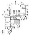
- eine schematische Seitenansicht des unteren Bereichs einer Armatur, die mittels einer Haltevorrichtung an einer Arbeitsplatte gehalten ist;
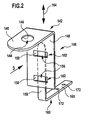
- Fig. 2
- eine perspektivische Darstellung der Haltevorrichtung aus
Fig. 1 ; - Fig. 3
- eine schematische Vorderansicht der Haltevorrichtung aus
Fig. 2 , mit Blickrichtung in Richtung des Pfeiles 3 inFig. 2 ; und - Fig. 4
- eine schematische Draufsicht auf einen horizontalen Halteschenkel eines armaturenseitigen Haltewinkels einer zweiten Ausführungsform der Haltevorrichtung.
- Gleiche oder funktional äquivalente Elemente sind in allen Figuren mit denselben Bezugszeichen bezeichnet.
- Eine in den
Fig. 1 bis 3 dargestellte, als Ganzes mit 100 bezeichnete Haltevorrichtung dient zum Haltern einer Armatur 102, die beispielsweise als Mischbatterie ausgebildet sein kann, an einer Spüle 104, welche in eine Aufnahmeöffnung 108 in einer Arbeitsplatte 106 eingesetzt ist. - Die Spüle 104 weist einen rings um die Spüle 104 umlaufenden, erhöhten horizontalen Spülenrand 110 auf, welcher auf dem Rand der Arbeitsplatte 106 ruht und über eine äußere Schräge 112 zu einer Oberseite 114 der Arbeitsplatte 106 hin abfällt und über eine innere Schräge 116 zu einer horizontalen Armaturentragefläche 118 der Spüle 104 hin abfällt.
- Die Armaturentragefläche 118 fällt über eine dem Spülenrand 110 abgewandte Schräge 120 zu einer horizontalen Spülenfläche 122 hin ab, in welcher das oder die Becken der Spüle 104 angeordnet sind.
- Die Armaturentragefläche 118 ist mit einer Durchgangsöffnung 124 für den Durchtritt eines Anschlußrohrs 126 der Armatur 102 versehen, welche ferner einen Armaturenkörper 128 umfaßt, dessen Unterseite 130 im montierten Zustand der Armatur 102 an der Oberseite 132 der Armaturentragefläche 118 anliegt.
- Das Anschlußrohr 126 ist mit einem Außengewinde 134 versehen, auf welches eine Fixiermutter 136 aufgeschraubt ist.
- Zwischen der Oberseite der Fixiermutter 136 und der Unterseite 138 der Armaturentragefläche 118 ist im montierten Zustand der Haltevorrichtung 100 ein horizontaler Anlageschenkel 140 eines ersten Haltewinkels 142 eingeklemmt, welcher mit seiner Oberseite flächig an der Unterseite 138 der Armaturentragefläche 118 und mit seiner Unterseite flächig an der Oberseite der Fixiermutter 136 anliegt.
- Wie am besten aus
Fig. 2 zu ersehen ist, ist der Anlageschenkel 140 des ersten Haltewinkels 142 mit einer Durchtrittsöffnung 144 für das Anschlußrohr 126 der Armatur 102 versehen, welche einen geschlossenen Rand 146 aufweist. - Der erste Haltewinkel 142 umfaßt ferner einen vertikalen Führungsschenkel 148, welcher mit zwei in vertikaler Richtung voneinander beabstandeten Führungslaschen 150 versehen ist.
- Diese Führungslaschen 150 sind dadurch gebildet, daß jeweils zwei horizontale Schnitte in dem Führungsschenkel 148 erzeugt werden und der Steg 154 zwischen jeweils zwei Schnitten zu der dem Anlageschenkel 140 abgewandten Seite des Führungsschenkels 148 hin aus der Ebene des Führungsschenkels 148 herausgebogen wird, so daß in dem Führungsschenkel 148 jeweils eine Durchgangsöffnung 156 entsteht.
- Im montierten Zustand der Haltevorrichtung 100 erstreckt sich ein vertikaler Führungsschenkel 158 eines zweiten Haltewinkels 160 zwischen den Führungslaschen 150 und der jeweils zugeordneten Durchgangsöffnung 156 hindurch, so daß die Führungslaschen 150 zusammen eine Führung 162 bilden, mittels welcher der Führungsschenkel 158 des zweiten Haltewinkels 160 längs einer vertikalen Verschiebungsrichtung 164 verschieblich an dem Führungsschenkel 148 des ersten Haltewinkels 142 geführt ist.
- Dabei liegt die dem ersten Haltewinkel 142 zugewandte Vorderseite des Führungsschenkels 158 flächig an der Rückseite des Führungsschenkels 148 des ersten Haltewinkels 142 an, während die dem ersten Haltewinkel 142 abgewandte Rückseite des Führungsschenkels 158 im wesentlichen spielfrei an den Führungslaschen 150 anliegt.
- Der Führungsschenkel 158 des zweiten Haltewinkels 160 verjüngt sich zu seinem oberen Ende hin, um das Einführen des Führungsschenkels 158 in die Führungslaschen 150 des ersten Haltewinkels 152 zu erleichtern.
- Der zweite Haltewinkel 160 umfaßt ferner einen im montierten Zustand der Haltevorrichtung 100 horizontal ausgerichteten Anlageschenkel 166, dessen Oberseite 168 flächig an der Unterseite 170 der Arbeitsplatte 106 anliegt.
- Der Anlageschenkel 166 des zweiten Haltewinkels 160 ist mit einem oder mehreren Durchgangslöchern 172 für den Durchtritt jeweils eines Befestigungsmittels 174, beispielsweise einer Holzschraube, durch den Anlageschenkel 166 versehen.
- Alternativ oder ergänzend zu einer Festlegung des Anlageschenkels 166 des zweiten Haltewinkels 160 an der Arbeitsplatte 106 mittels des Befestigungsmittels 174 kann vorgesehen sein, daß die Oberseite 168 des Anlageschenkels 166 mittels eines geeigneten Klebemittels mit der Unterseite 170 der Arbeitsplatte 106 verklebt ist.
- Um zu verhindern, daß Wasser von der Oberseite 114 der Arbeitsplatte 106 in den Bereich unterhalb der Spüle 104 gelangen kann, ist zwischen der Oberseite 114 der Arbeitsplatte 106 und der Unterseite des Spülenrands 110 eine Dichtung 176 aus einer elastischen Kunststoff-Dichtungsmasse, beispielsweise aus Silikon, vorgesehen.
- Bei der Montage der Armatur 102 an der Spüle 104 und der Spüle 104 an der Arbeitsplatte 106 wird wie folgt vorgegangen:
- Zunächst wird das Anschlußrohr 126 der Armatur 102 von oben durch die Durchgangsöffnung 124 in der Armaturentragefläche 118 der Spüle 104 hindurchgeführt, bis der Armaturenkörper 128 von oben an der Armaturentragefläche 118 anliegt.
- Anschließend wird der erste Haltewinkel 142 der Haltevorrichtung 100 so auf das Anschlußrohr 126 aufgesteckt, daß das Anschlußrohr 126 durch die Durchtrittsöffnung 144 in dem Anlageschenkel 140 hindurchtritt.
- In dieser Lage wird der erste Haltewinkel 142 durch Anziehen der Fixiermutter 136 festgelegt.
- Anschließend wird die Spüle 104 in die Aufnahmeöffnung 108 der Arbeitsplatte 106 eingesetzt und an der Arbeitsplatte 106 festgelegt.
- Darauf wird der zweite Haltewinkel 160 mit dem Führungsschenkel 158 voran von unten in die Führungslaschen 150 des Führungsschenkels 148 des ersten Haltewinkels 142 eingeschoben, bis die Oberseite 168 des Anlageschenkels 166 des zweiten Haltewinkels 160 an der Unterseite 170 der Arbeitsplatte 106 anliegt.
- Durch die Verschiebbarkeit des zweiten Haltewinkels 160 relativ zu dem ersten Haltewinkel 142 ist somit gewährleistet, daß der Anlageschenkel 166 des zweiten Haltewinkels 160 unabhängig von der Dicke der Arbeitsplatte 106 stets zur Anlage an der Unterseite 170 der Arbeitsplatte 106 gebracht werden kann.
- Schließlich wird der Anlageschenkel 166 des zweiten Haltewinkels 160 durch Kleben und/oder Verschrauben an der Arbeitsplatte 106 festgelegt, womit die Montage der Haltevorrichtung 100 abgeschlossen ist.
- Bei der vorstehend beschriebenen Montage der Haltevorrichtung 100 werden keinerlei Zug- oder Druckkräfte in vertikaler Richtung auf die Spüle 104 oder auf die Armatur 102 ausgeübt.
- Im Betrieb der Armatur 102 an der Spüle 104 werden durch die Haltevorrichtung 100 sämtliche horizontal gerichteten Kräfte sowie alle auftretenden Drehmomente vollständig und zuverlässig durch die Haltevorrichtung 100 von der Armatur 102 auf die Arbeitsplatte 106 übertragen.
- Auf diese Weise ist eine stabile Fixierung der Armatur 102 gewährleistet, welche auch für besonders schwere Armaturen 102, beispielsweise für mit Schlauchbrausen versehene Mischbatterien, ausreichend ist.
- Eine in
Fig. 4 dargestellte zweite Ausführungsform einer Haltevorrichtung 100 unterscheidet sich von der vorstehend beschriebenen ersten Ausführungsform lediglich dadurch, daß der Anlageschenkel 140 des ersten Haltewinkels 142 nicht mit einer einzelnen Durchtrittsöffnung 144 mit geschlossenem Rand, sondern statt dessen mit einer großen Durchtrittsöffnung 144' und einer kleineren Durchtrittsöffnung 144" versehen ist, wobei keine dieser Durchtrittsöffnungen einen geschlossenen Rand aufweist, sondern die größere Durchtrittsöffnung 144' am vorderen Rand des Anlageschenkels 140 mündet und die kleinere Durchtrittsöffnung 144" an ihrem vorderen Ende in die größere Durchtrittsöffnung 144' mündet. - Durch das Vorhandensein von zwei Durchtrittsöffnungen 144', 144" in dem Anlageschenkel 140 des ersten Haltewinkels 142 ist gewährleistet, daß die Haltevorrichtung 100 zum Haltern von Armaturen 102 mit unterschiedlich dicken Anschlußrohren 126 verwendet werden kann, wobei die Haltevorrichtung 100 jeweils so angeordnet wird, daß das Anschlußrohr 126 durch die am besten passende Durchtrittsöffnung 144', 144" hindurchtritt.
- Im übrigen stimmt die zweite Ausführungsform einer Haltevorrichtung 100 hinsichtlich Aufbau und Funktion mit der ersten Ausführungsform überein, auf deren vorstehende Beschreibung insoweit Bezug genommen wird.
Claims (14)
- Haltevorrichtung zum Haltern einer Armatur (102) an einer Spüle (104), die an einer Arbeitsplatte (106) angeordnet ist, wobei die Haltevorrichtung ein erstes Halteelement (142), das im montierten Zustand der Haltevorrichtung (100) an der Armatur (102) festgelegt ist und mindestens eine Durchtrittsöffnung (144; 144', 144") für die Armatur (102) aufweist, durch welche sich im montierten Zustand der Haltevorrichtung (100) das Anschlußrohr der Armatur (102) hindurcherstreckt, und ein zweites Halteelement (160), das im montierten Zustand der Haltevorrichtung (100) an der Arbeitsplatte (106) festgelegt ist, umfasst, wobei das erste Halteelement (142) und das zweite Halteelement (160) im montierten Zustand der Haltevorrichtung (100) so miteinander verbunden sind, dass Kräfte von dem ersten Halteelement (142) auf das zweite Halteelement (160) übertragbar sind.
- Haltevorrichtung nach Anspruch 1, dadurch gekennzeichnet, dass das erste Halteelement (142) winkelförmig ausgebildet ist.
- Haltevorrichtung nach einem der Ansprüche 1 oder 2, dadurch gekennzeichnet, dass das zweite Halteelement (160) winkelförmig ausgebildet ist.
- Haltevorrichtung nach einem der Ansprüche 1 bis 3, dadurch gekennzeichnet, dass die Durchtrittsöffnung (144) einen geschlossenen Rand (146) aufweist.
- Haltevorrichtung nach einem der Ansprüche 1 bis 4, dadurch gekennzeichnet, dass das erste Halteelement (142) mindestens zwei Durchtrittsöffnungen (144', 144") für die Armatur (102) aufweist.
- Haltevorrichtung nach Anspruch 5, dadurch gekennzeichnet, dass das erste Halteelement (142) mindestens zwei Durchtrittsöffnungen (144', 144") unterschiedlicher Größe aufweist.
- Haltevorrichtung nach einem der Ansprüche 1 bis 6, dadurch gekennzeichnet, dass die Haltevorrichtung (100) eine Führung (162) umfasst, mittels welcher eines der Halteelemente (160) längs einer Verschiebungsrichtung (164) verschieblich an dem jeweils anderen Halteelement (142) geführt ist.
- Haltevorrichtung nach Anspruch 7, dadurch gekennzeichnet, dass die Führung (162) mindestens eine Führungslasche (150) umfasst, welche das geführte Halteelement (160) umgreift.
- Haltevorrichtung nach Anspruch 8, dadurch gekennzeichnet, dass die Führung (162) mindestens zwei längs der Verschiebungsrichtung (164) voneinander beabstandete Führungslaschen (150) umfasst, welche das geführte Halteelement (160) umgreifen.
- Haltevorrichtung nach einem der Ansprüche 7 bis 9, dadurch gekennzeichnet, dass die Verschiebungsrichtung (164) im montierten Zustand der Haltevorrichtung (100) im wesentlichen vertikal gerichtet ist.
- Haltevorrichtung nach einem der Ansprüche 1 bis 10, dadurch gekennzeichnet, dass das zweite Halteelement (160) eine Anlagefläche (168) umfasst, mit welcher das zweite Halteelement (160) im montierten Zustand der Haltevorrichtung (100) an der Arbeitsplatte (106) anliegt.
- Haltevorrichtung nach einem der Ansprüche 1 bis 11, dadurch gekennzeichnet, dass die Haltevorrichtung (100) mindestens ein Befestigungsmittel (174) zum Festlegen des zweiten Halteelements (160) an der Arbeitsplatte (106) umfasst.
- Armatur für eine Spüle (104), die an einer Arbeitsplatte (106) angeordnet ist, umfassend eine Haltevorrichtung (100) zum Haltern der Armatur (102) an der Spüle (104) nach einem der Ansprüche 1 bis 12.
- Spüle zum Anordnen an einer Arbeitsplatte (106), umfassend eine Armatur (102) mit einer Haltevorrichtung (100) zum Haltern der Armatur (102) an der Spüle (104) nach einem der Ansprüche 1 bis 12.
Applications Claiming Priority (2)
| Application Number | Priority Date | Filing Date | Title |
|---|---|---|---|
| DE10251568 | 2002-11-06 | ||
| DE10251568A DE10251568A1 (de) | 2002-11-06 | 2002-11-06 | Haltevorrichtung zum Haltern einer Armatur an einer Spüle, die an einer Arbeitsplatte angeordnet ist |
Publications (3)
| Publication Number | Publication Date |
|---|---|
| EP1418281A2 EP1418281A2 (de) | 2004-05-12 |
| EP1418281A3 EP1418281A3 (de) | 2004-12-01 |
| EP1418281B1 true EP1418281B1 (de) | 2008-12-24 |
Family
ID=32103361
Family Applications (1)
| Application Number | Title | Priority Date | Filing Date |
|---|---|---|---|
| EP03025062A Expired - Lifetime EP1418281B1 (de) | 2002-11-06 | 2003-10-31 | Haltevorrichtung zum Haltern einer Armatur an einer Spüle, die an einer Arbeitsplatte angeordnet ist |
Country Status (5)
| Country | Link |
|---|---|
| EP (1) | EP1418281B1 (de) |
| AT (1) | ATE418650T1 (de) |
| DE (2) | DE10251568A1 (de) |
| DK (1) | DK1418281T3 (de) |
| ES (1) | ES2316687T3 (de) |
Cited By (1)
| Publication number | Priority date | Publication date | Assignee | Title |
|---|---|---|---|---|
| DE102021207776A1 (de) | 2021-07-21 | 2023-01-26 | BSH Hausgeräte GmbH | Anordnung mit einem Spülbecken und einem Wasserhahn sowie mit einer spezifischen Verspannvorrichtung, sowie Verfahren |
Families Citing this family (2)
| Publication number | Priority date | Publication date | Assignee | Title |
|---|---|---|---|---|
| DE202008000817U1 (de) * | 2008-01-18 | 2008-03-27 | Niro-Plan Ag | Befestigungsvorrichtung zum Fixieren einer Armatur an einer von einem Möbel getragenen Spüle |
| DE102018116334A1 (de) * | 2018-07-05 | 2020-01-09 | Franke Technology And Trademark Ltd. | Armaturenverstärkung für eine Spüle |
Family Cites Families (7)
| Publication number | Priority date | Publication date | Assignee | Title |
|---|---|---|---|---|
| DE8810505U1 (de) * | 1988-08-19 | 1989-02-23 | BTS-Bau-Installations-Systeme GmbH, 8755 Alzenau | Vorrichtung zur Halterung von Anschlußdosen für Kalt- und Warmwasserarmaturen |
| US5135022A (en) * | 1991-01-17 | 1992-08-04 | Masco Corporation Of Indiana | Vertically adjustable valve fitting assembly for tubs |
| US5143121A (en) * | 1991-11-08 | 1992-09-01 | Kohler Co. | Fluid pulse generating apparatus |
| DE4431869A1 (de) * | 1994-09-07 | 1996-03-14 | Knebel & Roettger Fa | Vorrichtung zur Befestigung einer Armatur an einer Arbeitsplatte, Spüle oder dergleichen |
| DE4443668C2 (de) * | 1994-12-08 | 2000-03-30 | Grohe Armaturen Friedrich | Auslaufarmatur mit Befestigungseinrichtung |
| DE19860186A1 (de) * | 1998-06-29 | 1999-12-30 | Aquis Gmbh Rebstein | Spülvorrichtung mit Spülbecken |
| GB9924080D0 (en) * | 1999-10-13 | 1999-12-15 | Springfast Ltd | Improvements relating to fasteners |
-
2002
- 2002-11-06 DE DE10251568A patent/DE10251568A1/de not_active Withdrawn
-
2003
- 2003-10-31 DE DE50310968T patent/DE50310968D1/de not_active Expired - Lifetime
- 2003-10-31 EP EP03025062A patent/EP1418281B1/de not_active Expired - Lifetime
- 2003-10-31 DK DK03025062T patent/DK1418281T3/da active
- 2003-10-31 ES ES03025062T patent/ES2316687T3/es not_active Expired - Lifetime
- 2003-10-31 AT AT03025062T patent/ATE418650T1/de active
Cited By (1)
| Publication number | Priority date | Publication date | Assignee | Title |
|---|---|---|---|---|
| DE102021207776A1 (de) | 2021-07-21 | 2023-01-26 | BSH Hausgeräte GmbH | Anordnung mit einem Spülbecken und einem Wasserhahn sowie mit einer spezifischen Verspannvorrichtung, sowie Verfahren |
Also Published As
| Publication number | Publication date |
|---|---|
| EP1418281A3 (de) | 2004-12-01 |
| DE50310968D1 (de) | 2009-02-05 |
| ES2316687T3 (es) | 2009-04-16 |
| EP1418281A2 (de) | 2004-05-12 |
| DK1418281T3 (da) | 2009-03-30 |
| ATE418650T1 (de) | 2009-01-15 |
| DE10251568A1 (de) | 2004-05-27 |
Similar Documents
| Publication | Publication Date | Title |
|---|---|---|
| AT13849U1 (de) | Befestigungsanordnung für einen Wasserhahn | |
| EP1699981B1 (de) | Sanit rarmatur mit einlochbefestigung | |
| DE202007005020U1 (de) | Mehrzweck-Stützgestell | |
| EP1418281B1 (de) | Haltevorrichtung zum Haltern einer Armatur an einer Spüle, die an einer Arbeitsplatte angeordnet ist | |
| EP1418282B1 (de) | Haltevorrichtung zum Haltern einer Armatur an einer Spüle, die an einer Arbeitsplatte angeordnet ist | |
| DE3823000A1 (de) | Befestigungselement | |
| EP2122084A1 (de) | Befestigungsvorrichtung | |
| EP0407352A2 (de) | Vorrichtung zur Befestigung eines Montagerahmens für Sanitärapparate | |
| EP1770224B1 (de) | Befestigungsvorrichtung zur Fixierung einer Armatur an einer Spüle, die an einer Arbeitsplatte angeordnet ist | |
| DE29819469U1 (de) | Befestigungsvorrichtung für Toilettenbrillen und/oder -deckel | |
| EP1510625A1 (de) | Befestigungsvorrichtung für die Wandmontage von sanitären Elementen | |
| AT408107B (de) | Vorrichtung zum befestigen eines kalt- und eines warmwasseranschlusses an einer blendwand | |
| DE102008062231B4 (de) | Befestigungsanordnung zum Befestigen einer Sanitärarmatur sowie Adapter | |
| DE102004036634A1 (de) | Vorrichtung zum Begasen von Flüssigkeiten und Verfahren zur Montage der Vorrichtung | |
| DE202005004524U1 (de) | Steckverbinder | |
| DE10016504A1 (de) | Befestigungsvorrichtung für eine Armatur auf ihrer Unterlage | |
| EP2080838A2 (de) | Befestigungsvorrichtung zum Fixieren einer Armatur an einer von einem Möbel getragenen Spüle | |
| DE102004058938B4 (de) | U-förmiges Klemmstück | |
| DE202024100539U1 (de) | Stanz- und/oder Biegeteil und Vorwand-Montagerahmen für eine Sanitärinstallation | |
| DE202010000963U1 (de) | Duschablaufanordnung | |
| DE3018016A1 (de) | Agraffe zur befestigung eines fassadenelements | |
| DE202018100960U1 (de) | Wandanschlusseinheit zum Anschließen einer Wasserarmatur an eine in einer Wand verlegten Wasserleitung | |
| AT409645B (de) | Vorrichtung zum befestigen eines abwasserrohres an einer montageschiene | |
| DE8210880U1 (de) | Einbaubecken, insbesondere einbauspuelbecken aus metall | |
| DE10328647B4 (de) | Montageelement und Bedienelement für eine Spüle |
Legal Events
| Date | Code | Title | Description |
|---|---|---|---|
| PUAI | Public reference made under article 153(3) epc to a published international application that has entered the european phase |
Free format text: ORIGINAL CODE: 0009012 |
|
| AK | Designated contracting states |
Kind code of ref document: A2 Designated state(s): AT BE BG CH CY CZ DE DK EE ES FI FR GB GR HU IE IT LI LU MC NL PT RO SE SI SK TR |
|
| AX | Request for extension of the european patent |
Extension state: AL LT LV MK |
|
| PUAL | Search report despatched |
Free format text: ORIGINAL CODE: 0009013 |
|
| AK | Designated contracting states |
Kind code of ref document: A3 Designated state(s): AT BE BG CH CY CZ DE DK EE ES FI FR GB GR HU IE IT LI LU MC NL PT RO SE SI SK TR |
|
| AX | Request for extension of the european patent |
Extension state: AL LT LV MK |
|
| 17P | Request for examination filed |
Effective date: 20050409 |
|
| AKX | Designation fees paid |
Designated state(s): AT BE BG CH CY CZ DE DK EE ES FI FR GB GR HU IE IT LI LU MC NL PT RO SE SI SK TR |
|
| 17Q | First examination report despatched |
Effective date: 20060515 |
|
| GRAP | Despatch of communication of intention to grant a patent |
Free format text: ORIGINAL CODE: EPIDOSNIGR1 |
|
| GRAS | Grant fee paid |
Free format text: ORIGINAL CODE: EPIDOSNIGR3 |
|
| GRAA | (expected) grant |
Free format text: ORIGINAL CODE: 0009210 |
|
| AK | Designated contracting states |
Kind code of ref document: B1 Designated state(s): AT BE BG CH CY CZ DE DK EE ES FI FR GB GR HU IE IT LI LU MC NL PT RO SE SI SK TR |
|
| REG | Reference to a national code |
Ref country code: GB Ref legal event code: FG4D Free format text: NOT ENGLISH |
|
| REG | Reference to a national code |
Ref country code: CH Ref legal event code: NV Representative=s name: ISLER & PEDRAZZINI AG Ref country code: CH Ref legal event code: EP |
|
| REG | Reference to a national code |
Ref country code: IE Ref legal event code: FG4D Free format text: LANGUAGE OF EP DOCUMENT: GERMAN |
|
| REF | Corresponds to: |
Ref document number: 50310968 Country of ref document: DE Date of ref document: 20090205 Kind code of ref document: P |
|
| REG | Reference to a national code |
Ref country code: DK Ref legal event code: T3 |
|
| REG | Reference to a national code |
Ref country code: ES Ref legal event code: FG2A Ref document number: 2316687 Country of ref document: ES Kind code of ref document: T3 |
|
| PG25 | Lapsed in a contracting state [announced via postgrant information from national office to epo] |
Ref country code: NL Free format text: LAPSE BECAUSE OF FAILURE TO SUBMIT A TRANSLATION OF THE DESCRIPTION OR TO PAY THE FEE WITHIN THE PRESCRIBED TIME-LIMIT Effective date: 20081224 Ref country code: FI Free format text: LAPSE BECAUSE OF FAILURE TO SUBMIT A TRANSLATION OF THE DESCRIPTION OR TO PAY THE FEE WITHIN THE PRESCRIBED TIME-LIMIT Effective date: 20081224 Ref country code: SI Free format text: LAPSE BECAUSE OF FAILURE TO SUBMIT A TRANSLATION OF THE DESCRIPTION OR TO PAY THE FEE WITHIN THE PRESCRIBED TIME-LIMIT Effective date: 20081224 |
|
| NLV1 | Nl: lapsed or annulled due to failure to fulfill the requirements of art. 29p and 29m of the patents act | ||
| REG | Reference to a national code |
Ref country code: IE Ref legal event code: FD4D |
|
| PG25 | Lapsed in a contracting state [announced via postgrant information from national office to epo] |
Ref country code: RO Free format text: LAPSE BECAUSE OF FAILURE TO SUBMIT A TRANSLATION OF THE DESCRIPTION OR TO PAY THE FEE WITHIN THE PRESCRIBED TIME-LIMIT Effective date: 20081224 Ref country code: EE Free format text: LAPSE BECAUSE OF FAILURE TO SUBMIT A TRANSLATION OF THE DESCRIPTION OR TO PAY THE FEE WITHIN THE PRESCRIBED TIME-LIMIT Effective date: 20081224 Ref country code: BG Free format text: LAPSE BECAUSE OF FAILURE TO SUBMIT A TRANSLATION OF THE DESCRIPTION OR TO PAY THE FEE WITHIN THE PRESCRIBED TIME-LIMIT Effective date: 20090324 Ref country code: IE Free format text: LAPSE BECAUSE OF FAILURE TO SUBMIT A TRANSLATION OF THE DESCRIPTION OR TO PAY THE FEE WITHIN THE PRESCRIBED TIME-LIMIT Effective date: 20081224 |
|
| PG25 | Lapsed in a contracting state [announced via postgrant information from national office to epo] |
Ref country code: PT Free format text: LAPSE BECAUSE OF FAILURE TO SUBMIT A TRANSLATION OF THE DESCRIPTION OR TO PAY THE FEE WITHIN THE PRESCRIBED TIME-LIMIT Effective date: 20090525 Ref country code: SE Free format text: LAPSE BECAUSE OF FAILURE TO SUBMIT A TRANSLATION OF THE DESCRIPTION OR TO PAY THE FEE WITHIN THE PRESCRIBED TIME-LIMIT Effective date: 20090324 |
|
| PG25 | Lapsed in a contracting state [announced via postgrant information from national office to epo] |
Ref country code: SK Free format text: LAPSE BECAUSE OF FAILURE TO SUBMIT A TRANSLATION OF THE DESCRIPTION OR TO PAY THE FEE WITHIN THE PRESCRIBED TIME-LIMIT Effective date: 20081224 |
|
| PLBE | No opposition filed within time limit |
Free format text: ORIGINAL CODE: 0009261 |
|
| STAA | Information on the status of an ep patent application or granted ep patent |
Free format text: STATUS: NO OPPOSITION FILED WITHIN TIME LIMIT |
|
| 26N | No opposition filed |
Effective date: 20090925 |
|
| PG25 | Lapsed in a contracting state [announced via postgrant information from national office to epo] |
Ref country code: MC Free format text: LAPSE BECAUSE OF NON-PAYMENT OF DUE FEES Effective date: 20091031 |
|
| PG25 | Lapsed in a contracting state [announced via postgrant information from national office to epo] |
Ref country code: GR Free format text: LAPSE BECAUSE OF FAILURE TO SUBMIT A TRANSLATION OF THE DESCRIPTION OR TO PAY THE FEE WITHIN THE PRESCRIBED TIME-LIMIT Effective date: 20090325 |
|
| PGFP | Annual fee paid to national office [announced via postgrant information from national office to epo] |
Ref country code: AT Payment date: 20101014 Year of fee payment: 8 |
|
| PGFP | Annual fee paid to national office [announced via postgrant information from national office to epo] |
Ref country code: DE Payment date: 20101127 Year of fee payment: 8 |
|
| PGFP | Annual fee paid to national office [announced via postgrant information from national office to epo] |
Ref country code: IT Payment date: 20101022 Year of fee payment: 8 Ref country code: GB Payment date: 20101027 Year of fee payment: 8 |
|
| PG25 | Lapsed in a contracting state [announced via postgrant information from national office to epo] |
Ref country code: LU Free format text: LAPSE BECAUSE OF NON-PAYMENT OF DUE FEES Effective date: 20091031 |
|
| PG25 | Lapsed in a contracting state [announced via postgrant information from national office to epo] |
Ref country code: HU Free format text: LAPSE BECAUSE OF FAILURE TO SUBMIT A TRANSLATION OF THE DESCRIPTION OR TO PAY THE FEE WITHIN THE PRESCRIBED TIME-LIMIT Effective date: 20090625 |
|
| PG25 | Lapsed in a contracting state [announced via postgrant information from national office to epo] |
Ref country code: TR Free format text: LAPSE BECAUSE OF FAILURE TO SUBMIT A TRANSLATION OF THE DESCRIPTION OR TO PAY THE FEE WITHIN THE PRESCRIBED TIME-LIMIT Effective date: 20081224 |
|
| PG25 | Lapsed in a contracting state [announced via postgrant information from national office to epo] |
Ref country code: CY Free format text: LAPSE BECAUSE OF FAILURE TO SUBMIT A TRANSLATION OF THE DESCRIPTION OR TO PAY THE FEE WITHIN THE PRESCRIBED TIME-LIMIT Effective date: 20081224 |
|
| PGFP | Annual fee paid to national office [announced via postgrant information from national office to epo] |
Ref country code: CZ Payment date: 20110929 Year of fee payment: 9 |
|
| PGFP | Annual fee paid to national office [announced via postgrant information from national office to epo] |
Ref country code: CH Payment date: 20111012 Year of fee payment: 9 Ref country code: BE Payment date: 20111012 Year of fee payment: 9 Ref country code: DK Payment date: 20111011 Year of fee payment: 9 Ref country code: FR Payment date: 20111103 Year of fee payment: 9 Ref country code: ES Payment date: 20111115 Year of fee payment: 9 |
|
| BERE | Be: lapsed |
Owner name: BLANCO G.M.B.H. + CO KG Effective date: 20121031 |
|
| REG | Reference to a national code |
Ref country code: CH Ref legal event code: PL |
|
| REG | Reference to a national code |
Ref country code: DK Ref legal event code: EBP |
|
| REG | Reference to a national code |
Ref country code: AT Ref legal event code: MM01 Ref document number: 418650 Country of ref document: AT Kind code of ref document: T Effective date: 20121031 |
|
| GBPC | Gb: european patent ceased through non-payment of renewal fee |
Effective date: 20121031 |
|
| REG | Reference to a national code |
Ref country code: FR Ref legal event code: ST Effective date: 20130628 |
|
| PG25 | Lapsed in a contracting state [announced via postgrant information from national office to epo] |
Ref country code: BE Free format text: LAPSE BECAUSE OF NON-PAYMENT OF DUE FEES Effective date: 20121031 Ref country code: CH Free format text: LAPSE BECAUSE OF NON-PAYMENT OF DUE FEES Effective date: 20121031 Ref country code: LI Free format text: LAPSE BECAUSE OF NON-PAYMENT OF DUE FEES Effective date: 20121031 Ref country code: GB Free format text: LAPSE BECAUSE OF NON-PAYMENT OF DUE FEES Effective date: 20121031 Ref country code: AT Free format text: LAPSE BECAUSE OF NON-PAYMENT OF DUE FEES Effective date: 20121031 Ref country code: DE Free format text: LAPSE BECAUSE OF NON-PAYMENT OF DUE FEES Effective date: 20130501 Ref country code: CZ Free format text: LAPSE BECAUSE OF NON-PAYMENT OF DUE FEES Effective date: 20121031 |
|
| REG | Reference to a national code |
Ref country code: DE Ref legal event code: R119 Ref document number: 50310968 Country of ref document: DE Effective date: 20130501 |
|
| PG25 | Lapsed in a contracting state [announced via postgrant information from national office to epo] |
Ref country code: FR Free format text: LAPSE BECAUSE OF NON-PAYMENT OF DUE FEES Effective date: 20121031 Ref country code: IT Free format text: LAPSE BECAUSE OF NON-PAYMENT OF DUE FEES Effective date: 20121031 |
|
| PG25 | Lapsed in a contracting state [announced via postgrant information from national office to epo] |
Ref country code: DK Free format text: LAPSE BECAUSE OF NON-PAYMENT OF DUE FEES Effective date: 20121031 |
|
| REG | Reference to a national code |
Ref country code: ES Ref legal event code: FD2A Effective date: 20140207 |
|
| PG25 | Lapsed in a contracting state [announced via postgrant information from national office to epo] |
Ref country code: ES Free format text: LAPSE BECAUSE OF NON-PAYMENT OF DUE FEES Effective date: 20121101 |