EP1418315A2 - Verfahren und Vorrichtung zur Steuerung des Gasstroms von einem Kurbelwellegehäuse einer Brennkraftmaschine zum Anssaugrohr - Google Patents
Verfahren und Vorrichtung zur Steuerung des Gasstroms von einem Kurbelwellegehäuse einer Brennkraftmaschine zum Anssaugrohr Download PDFInfo
- Publication number
- EP1418315A2 EP1418315A2 EP03104094A EP03104094A EP1418315A2 EP 1418315 A2 EP1418315 A2 EP 1418315A2 EP 03104094 A EP03104094 A EP 03104094A EP 03104094 A EP03104094 A EP 03104094A EP 1418315 A2 EP1418315 A2 EP 1418315A2
- Authority
- EP
- European Patent Office
- Prior art keywords
- flow
- temperature
- gas
- engine
- valve assembly
- Prior art date
- Legal status (The legal status is an assumption and is not a legal conclusion. Google has not performed a legal analysis and makes no representation as to the accuracy of the status listed.)
- Granted
Links
Images



Classifications
-
- F—MECHANICAL ENGINEERING; LIGHTING; HEATING; WEAPONS; BLASTING
- F16—ENGINEERING ELEMENTS AND UNITS; GENERAL MEASURES FOR PRODUCING AND MAINTAINING EFFECTIVE FUNCTIONING OF MACHINES OR INSTALLATIONS; THERMAL INSULATION IN GENERAL
- F16K—VALVES; TAPS; COCKS; ACTUATING-FLOATS; DEVICES FOR VENTING OR AERATING
- F16K31/00—Actuating devices; Operating means; Releasing devices
- F16K31/02—Actuating devices; Operating means; Releasing devices electric; magnetic
- F16K31/025—Actuating devices; Operating means; Releasing devices electric; magnetic actuated by thermo-electric means
-
- F—MECHANICAL ENGINEERING; LIGHTING; HEATING; WEAPONS; BLASTING
- F02—COMBUSTION ENGINES; HOT-GAS OR COMBUSTION-PRODUCT ENGINE PLANTS
- F02M—SUPPLYING COMBUSTION ENGINES IN GENERAL WITH COMBUSTIBLE MIXTURES OR CONSTITUENTS THEREOF
- F02M25/00—Engine-pertinent apparatus for adding non-fuel substances or small quantities of secondary fuel to combustion-air, main fuel or fuel-air mixture
- F02M25/06—Engine-pertinent apparatus for adding non-fuel substances or small quantities of secondary fuel to combustion-air, main fuel or fuel-air mixture adding lubricant vapours
-
- F—MECHANICAL ENGINEERING; LIGHTING; HEATING; WEAPONS; BLASTING
- F16—ENGINEERING ELEMENTS AND UNITS; GENERAL MEASURES FOR PRODUCING AND MAINTAINING EFFECTIVE FUNCTIONING OF MACHINES OR INSTALLATIONS; THERMAL INSULATION IN GENERAL
- F16K—VALVES; TAPS; COCKS; ACTUATING-FLOATS; DEVICES FOR VENTING OR AERATING
- F16K31/00—Actuating devices; Operating means; Releasing devices
- F16K31/002—Actuating devices; Operating means; Releasing devices actuated by temperature variation
-
- Y—GENERAL TAGGING OF NEW TECHNOLOGICAL DEVELOPMENTS; GENERAL TAGGING OF CROSS-SECTIONAL TECHNOLOGIES SPANNING OVER SEVERAL SECTIONS OF THE IPC; TECHNICAL SUBJECTS COVERED BY FORMER USPC CROSS-REFERENCE ART COLLECTIONS [XRACs] AND DIGESTS
- Y02—TECHNOLOGIES OR APPLICATIONS FOR MITIGATION OR ADAPTATION AGAINST CLIMATE CHANGE
- Y02T—CLIMATE CHANGE MITIGATION TECHNOLOGIES RELATED TO TRANSPORTATION
- Y02T10/00—Road transport of goods or passengers
- Y02T10/10—Internal combustion engine [ICE] based vehicles
- Y02T10/12—Improving ICE efficiencies
Definitions
- the invention relates to method and apparatus for controlling the flow of gas from an engine crankcase to an engine intake manifold.
- crankcase ventilation (PCV) valves have long been used to remove crankcases gases from the crankcase of an engine.
- Crankcases gases are a combination of (i) blow-by gases, (i.e., combusted and non-combusted combustion chamber gases which migrate past piston rings into the crankcase), (ii) fuel, (iii) air and (iv) oil vapour.
- PCV valves regulate the removal of crankcase gases from the crankcase by venting the gases into the engine intake manifold.
- PCV valve One known PCV valve is disclosed in U.S. Patent No. 3,709,204.
- the known PCV valve shuts off the flow of gases from a crankcase to an intake manifold until the temperature of the engine has increased above a predetermined temperature.
- the known valve shuts off flow of the gases during cold engine starting.
- Another similar PCV valve system is disclosed in U.S. Patent No. 3,263,660 that shuts off flow during cold engine starting.
- crankcase gases there are several disadvantages with stopping the flow of crankcase gases from a crankcase to an intake manifold during cold operating conditions.
- crankcase gases are more likely to react with oil to form sludge, which in turn can adversely effect the oil lubrication properties resulting in increased engine wear.
- stopping the flow of fresh air into the crankcase can increase the tendency of engine oil sludge formation.
- the inventors herein have recognized that because a by-product of combustion is water, the crankcase gases are relatively humid.
- stopping the flow of fresh air into the crankcase results in a relatively high crankcase humidity where the water vapour can freeze within the PCV valve during cold operating conditions. This ice formation can adversely effect the operation of the PCV valve until the valve is de-thawed.
- a method for controlling the flow of gas through a passage between an engine crankcase and an engine intake manifold characterised in that the method comprises increasing the flow of gas through the passage between the crankcase and the intake manifold when a temperature of the gas is below a predetermined temperature.
- the step of increasing the flow of gas through the passage may include decreasing a flow path restriction of the gas when the temperature is below the predetermined temperature.
- the method may further comprise controlling the flow of gas through the passage between the crankcase and the intake manifold when a temperature of the gas is above the predetermined temperature.
- valve assembly for controlling the flow of gas through a passage between an engine crankcase and an engine intake manifold characterised in that the valve assembly comprises a housing configured to be coupled with the passage and a flow control device disposed in the housing to increase the flow of gas through the housing when a temperature of the gas is below a predetermined temperature.
- the housing may include an inlet aperture connecting the passage to the housing and the flow control device includes a piston configured to move adjacent the inlet aperture and an actuator coupled to the piston wherein the actuator is operable to move the piston to increase the flow of gas through the aperture when the temperature of the gases is below the predetermined temperature.
- the valve assembly may further comprise a vacuum actuated pintle disposed downstream of the flow control device and the flow control device may further comprise a sleeve member configured to be concentrically received around a portion of the pintle at a first position to restrict flow of gases through the housing and being further configured to be moved to a second position away from the pintle to increase the flow of gas through the housing and an actuator coupled to the sleeve to move the sleeve toward the second axial position when the temperature of the gas is below the predetermined temperature.
- the actuator may comprise one of a wax motor, a bi-metallic actuator and an electrically actuated solenoid.
- a control system for controlling flow of gases through a passage between an engine crankcase and an engine intake manifold characterised in that the system comprises a temperature sensor generating a first signal indicative of a temperature of the engine, a valve assembly having a housing coupled to the passage and a flow control device disposed in the housing operable to increase the flow of the gas through the housing is response to a second signal and a controller operably connected to the temperature sensor and the valve assembly wherein the controller is operable to generate the second signal when the first signal indicates that the temperature is below a predetermined temperature.
- the temperature may be one of a temperature of the gas communicating with the valve assembly, an engine oil temperature, an engine coolant temperature and an engine block temperature.
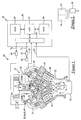
- an automotive vehicle 10 includes an internal combustion engine 12 and an engine control system 14.
- Engine 12 may include a plurality of cylinders in cylinder banks 16, 18.
- Engine 12 may further include an air filter 20, a throttle body 22, an intake manifold 24, an engine head 26, cam covers 28, 30, an engine block 32, an oil pan 34, a crankshaft 36, pistons 38, 40, a valve assembly comprising one of valve assemblies 42, 44, 46, 48 described below, and a catalytic converter 50.
- Engine 12 inducts air through filter 20 into both throttle body 22 and a conduit or passage 52.
- the air inducted into throttle body 22 is routed past throttle plate 70 to intake manifold 24. Thereafter, the air is inducted into the engine cylinders where an air-fuel mixture is combusted.
- a portion of the gases in cylinder banks 16, 18 hereinafter referred to as crankcase gas or gases migrate past pistons 38, 40 into an engine crankcase 54. As discussed above, these crankcase gases can mix with the oil in crankcase 54 to form sludge which can degrade performance of engine 12.
- crankcase 54 To remove the crankcase gases from crankcase 54, a portion of the air from air filter 20 is routed through a conduit 52 to an interior volume defined by cam cover 30. From the interior volume of cam cover 30, the inducted air flows through conduit 56 (in engine head 26) and conduit 58 (in engine block 32) to reach crankcase 54. In engine crankcase 54, the inducted air mixes with the blow-by gases and oil vapour to form a diluted mixture of crankcase gases.
- valve assemblies 42, 44, 46, 48 in accordance with the present invention will be utilized to control flow of the crankcase gases into intake manifold 24.
- a portion of valve assembly extends through a top surface of cam cover 28 to control the flow of crankcase gases into intake manifold 24.
- the gases flow through the valve assembly and through conduit 64 to intake manifold 24.
- the crankcase gases mix with incoming air from throttle body 22 and are inducted into the engine cylinders.
- crankcase gases and other combusted gases flow from the engine cylinders to catalytic converter 50 which is used to oxidize carbon monoxide (CO) and hydrocarbons (HC) and to reduce nitrogen oxides (NOx).
- catalytic converter 50 which is used to oxidize carbon monoxide (CO) and hydrocarbons (HC) and to reduce nitrogen oxides (NOx).
- Control system 14 is provided to control operation of engine 12.
- Control system 14 includes a current driver 66, an electric motor 68 for controlling throttle plate 70, an ETC driver 72, a throttle position sensor 74, a temperature sensor 76, and a controller 78.
- Current driver 66 is provided to generate a current to actuate a solenoid 80 in valve assembly 46 responsive to a signal (V A ) from controller 78, as discussed in greater detail below.
- Electric motor 68 is provided to move throttle plate 70 to a predetermined position responsive to a current received from ETC driver 72.
- ETC driver 72 generates the current responsive to a control signal (V T ) from controller 78.
- Throttle position sensor 74 generates a signal (TP) indicating a throttle position of throttle plate 70 received by controller 78 for closed-loop position control of plate 70.
- Temperature sensor 76 generates a signal (ET) indicative of an oil temperature that is received by controller 78.
- Sensor 76 may be coupled to oil pan 34. Alternately, sensor 76 could measure an engine coolant temperature (ECT), an engine block temperature, or any other temperature indicative of an operating condition of engine 12.
- ECT engine coolant temperature
- ECT engine block temperature
- Controller 78 is utilized to control operation of valve assembly 46 described in greater detail below.
- Controller 78 includes a microprocessor 82 communicating with various computer-readable storage media.
- the computer readable storage media preferably include non-volatile and volatile storage in a read-only memory (ROM) 84 and a random-access memory (RAM) 86.
- the computer readable media may be implemented using any of a number of known memory devices such as PROMs, EPROMs, EEPROMs, flash memory or any other electric, magnetic, optical or combination memory device capable of storing data, some of which represent executable instructions, used by microprocessor 82 in controlling engine 12.
- Microprocessor 82 communicates with various sensors and actuators (discussed above) via an input/output (I/O) interface 88.
- I/O input/output
- Valve assembly 42 in accordance with a first aspect of the present invention is shown.
- Valve assembly 42 is provided to control flow of gases from engine crankcase 54 to intake manifold 24.
- assembly 42 can decrease a flow of diluted crankcase gases during relatively warm engine conditions to reduce the amount of oil entering the intake and exhaust systems.
- the valve assembly 42 can increase a flow of diluted crankcase gases during relatively cold engine conditions to reduce sludge formation in crankcase 54.
- Valve assembly 42 includes a housing 90, an actuator 92, a piston 94, a pintle 96, and bias springs 98, 100.
- Housing 90 includes first, second, third housing portions 102, 104, 106 which may be constructed of metal.
- Housing portion 102 includes a closed-ended tubular wall 108 that defines an internal volume 110.
- Wall 108 is configured to hold an actuator such as a wax motor 92 therein and may be threadably coupled to a first end of housing portion 104.
- Housing portion 104 has an outer wall 112 that is generally tubular-shaped and defines an internal volume 114. Housing portion 104 is configured to hold piston 94 therein. Portion 104 includes an aperture 116 extending through outer wall 112 for communicating crankcase gases from an interior volume of cam cover 28 into valve assembly 42. Housing portion 104 has a second end that may be threadably coupled to housing portion 106.
- Housing portion 106 has an outer wall 120 that is generally tubular-shaped and defines an internal volume 118. Housing portion 106 includes a ring-shaped metering wall 122 extending inwardly from outer wall 120. Referring to Figures 3A, 7A, wall 122 is provided to define a metering orifice 124 between pintle 96 and wall 122 to control flow through assembly 42. As shown, pintle 96 is biased axially away from wall 122 via bias spring 98.
- wax motor 92 is provided to control a position of piston 94 to vary flow of crankcase gases through aperture 116 based on a temperature of the crankcase gases.
- the combination of wax motor 92 and piston 94 comprises a flow control device in assembly 42.
- Motor 92 includes a brass housing 126, a wax layer 128, a rubber boot 130, a drive pin 132, and a cap 134.
- Motor housing 126 is provided to conduct heat from housing portion 102 to wax layer 128 and may be disposed within housing portion 102.
- Motor housing 126 may be constructed from a thermally conductive metal such as brass for example.
- the wax layer 128 has a volume that expands and contracts based on a temperature of layer 128.
- Layer 128 expands when the temperature therein is above a predetermined temperature causing an adjacent rubber boot 130 move drive pin 132 in a first axial direction (right in Figure 8B).
- the predetermined temperature may be within the range of 49 to 54°C (120-130°F). It should be understood, however, that the predetermined temperature could be outside this range depending upon a desired temperature response of assembly 42.
- Layer 128 contracts when an internal temperature is below the predetermined temperature causing boot 130 to move drive pin 132 in a second axial direction (left in Figure 8A).
- Layer 128 is disposed within brass housing 126 and is composed of wax and copper particles. The ratio of the mass of wax to the mass of copper particles determines the predetermined temperature when the volume of layer 128 increases from the volume shown in Figure 8A to the larger volume shown in Figure 8B, as known to those skilled in the art.
- Rubber boot 130 is coupled between wax layer 128 and cap 134.
- Cap 134 may be constructed of metal and may be threadably coupled to motor housing 126.
- Drive pin 132 extends through an aperture 136 in cap 134 and is coupled at a first end to boot 130.
- Drive pin 132 is further coupled at a second end to piston 94.
- Drive pin 132 and piston 94 are moved axially by boot 130 responsive to the temperature-dependent volume of layer 128.
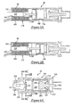
- piston 94 is provided to control a flow area through aperture 116. As shown, piston 94 has a first open operational position where crankcase gases are not restricted from flowing into housing 90. Referring to Figure 3B, piston 94 has a second closed operational position where crankcase gases are substantially restricted from flowing into housing 90. Bias spring 100 is disposed between piston 94 and wall 138 of housing portion 104 and biases piston 94 toward a closed position (to the left in Figure 3A). Thus, motor 92 must overcome the force of bias spring 100 to restrict flow through aperture 116.
- Pintle 96 includes body portions 140, 142, 144 and a flange section 146.
- valve assembly 42 The typical operational flow characteristics of assembly 42 are shown during cold and warm engine conditions in flow curves 148, 150, respectively. As shown, the flow during cold engine conditions (e.g., curve 148) is greater than the flow during hot engine conditions (e.g., curve 150).
- the flow offset between the curves 148, 150 is determined primarily by an operational position of piston 94.
- the shape of curves 148, 150 is determined primarily by the operational position of pintle 96 relative to the metering wall 122.
- the operational position of pintle 96 is determined based on the differential pressure (P DIFF ) between the cam cover pressure (P CC ) and the intake manifold pressure (P MAN ) as will be explained in greater detail below.
- crankcase gases are less than a predetermined temperature
- piston 94 is maintained at an open position relative to aperture 116.
- Crankcase gases enter aperture 116 from an interior volume of cam cover 28 with minimal flow restriction from piston 94.
- the curve 148 illustrates the flow characteristics of valve assembly 42 during the cold operating conditions.
- piston 94 is moved to a closed position relative to aperture 116. Accordingly, the flow of crankcase gases through aperture 116 is restricted by piston 94.
- the curve 150 illustrates the flow characteristics of valve assembly 42 during the warm operating conditions.
- valve assembly 42 based on the differential pressure (P DIFF ) will now be described in greater detail.
- pintle portion 144 is moved proximate wall 122 to obtain a relatively small metering orifice 124 which provides a relatively low flow rate through valve assembly 42.
- the radial distance between pintle portion 144 and wall 122 may be 0.35 mm for example.
- the differential pressure (P DIFF ) may between the values (P 3 ), (P 4 ).
- the flow rate through assembly 42 may be maintained at a relatively constant value as illustrated by flow values 152, 154.
- the flow rate may be maintained at a lower constant value as illustrated by flow values 156, 158.
- the differential pressure (P DIFF ) across assembly 42 may decrease from pressure value (P 3 ) to value (P 2 ). Further, during cold operating conditions, the flow rate illustrated by curve 148 may be increased from flow value 152 to flow value 160 while opening throttle plate 70. Similarly, during warm operating conditions, the flow rate illustrated by curve 150 may be increased from flow value 156 to flow value 162 while opening throttle plate 70.
- the combustion pressure (P COMB ) in the engine cylinders approaches a maximum value. This in turn causes the crankcase gases to flow at a maximum flow rate into crankcase 54.
- the differential pressure (P DIFF ) across valve assembly 42 approaches a minimum differential pressure.
- the relatively low differential pressure (P DIFF ) causes pintle 96 to move further left in Figure 3A.
- pintle portion 140 is moved proximate metering wall 122 to obtain the maximum sized metering orifice 124 to obtain a maximum flow through valve assembly 42.
- the radial distance between pintle portion 140 and wall 122 may be 1.85 mm, for example.
- the differential pressure (P DIFF ) across valve assembly 42 may range from pressure value (P 1 ) to value (P 2 ) depending on the robustness of the piston seals (not shown). For example, if the piston seals are substantially preventing crankcase gases from flowing to crankcase 54, the differential pressure (P DIFF ) would be equal to pressure value (P 1 ).
- the differential pressure (P DIFF ) could be equal to pressure value (P 2 ).
- the flow rate illustrated by curve 160 may range from flow value 164 to flow value 160.
- the flow rate illustrated by curve 162 may range from flow value 166 to flow value 162.
- valve assembly 44 in accordance with a second aspect of the present invention is shown.
- the valve assembly 44 is similar to valve assembly 42 except that wax motor 92 of assembly 42 is replaced with a bi-metallic actuator 168 and housing portion 102 is replaced with housing portion 170 and cap 172. Accordingly, only these new components will be discussed in detail since the remaining components of valve assembly 44 are identical to assembly 42 discussed above.
- Housing portion 170 may be threadably coupled at a first end to housing portion 104. Housing portion 170 includes an aperture 174 extending axially therethrough for receiving a drive pin 132. Cap 172 may be coupled to a second end of housing portion 170 to define an internal volume 176. Housing portion 170 and cap 172 may be constructed from a thermally conductive material such as steel.
- Bi-metallic actuator 168 is disposed in volume 176 and is constructed from two laminated metal layers 169 (not shown) having different heat expansion ratios, and drive pin 132.
- the metal layers 169 may be constructed from a first layer of invar adjacent a second layer of brass.
- the combination of actuator 168 and piston 96 comprises a flow control device in assembly 44. Referring to Figure 4A, when a temperature of the crankcase gases are below a predetermined temperature, actuator 168 flexes toward cap 134 to move piston 94 to an open position relative to aperture 116 to increase or maintain flow through valve assembly 44. Referring to Figure 4B, when the temperature of the crankcase gases increases above the predetermined temperature, actuator 168 flexes away from cap 172 to move piston 94 toward a closed position relative to aperture 116 to decrease flow through assembly 44.
- actuator 168 of valve assembly 44 decreases flow during warm operating conditions and increases flow during cold operating conditions. Further, referring to Figure 9, assembly 44 may have flow characteristics as illustrated by curves 148, 150.
- valve assembly 46 in accordance with a third aspect of the present invention is shown.
- Valve assembly 46 is similar to valve assembly 42 except that wax motor 92 of assembly 42 is replaced with a solenoid 80 and housing portion 102 is replaced with housing portion 178. Accordingly, only these new components will be discussed in detail since the remaining components of valve assembly 46 may be identical to assembly 42 discussed above.
- housing portion 178 may include an outer wall 180, a bottom wall 182 adjacent wall 180. Walls 180, 182 define an inner volume 184 for holding solenoid 80. Further, wall 182 may include an aperture 186 extending therethrough for receiving an armature 188 of solenoid 80.
- Solenoid 80 is disposed in volume 184 and includes a coil 189 surrounding armature 188.
- controller 78 determines an engine temperature is above a predetermined temperature
- the controller 78 will generate signal (V A ) to energize coil 88 at step 192.
- the energized coil 189 induces armature 188 to move piston 94 toward a closed position relative to aperture 116 to decrease flow through assembly 46.
- step 190 when controller 78 indicates an engine temperature is below a predetermined temperature, controller 78 will de-energize coil 88 at step 194.
- bias spring 100 in turn moves or holds piston 94 in an open position relative to aperture 116 to increase or maintain flow through aperture 116.
- solenoid 80 and piston 96 comprises a flow control device in assembly 46.
- solenoid 80 decreases flow through valve assembly 46 during warm operating conditions and increases flow through valve assembly 46 during cold operating conditions. Further, referring to Figure 9, assembly 46 may have flow characteristics as illustrated by curves 148, 150.
- valve assembly 48 in accordance with a fourth aspect of the present invention is shown.
- Valve assembly 48 operates similar as valve assembly 42 to decrease flow of crankcase gases through assembly 48 during warm operating conditions and to increase flow during cold operating conditions.
- Valve assembly 48 includes a housing 196, an actuator 92, a sleeve 198, a pintle 200, and bias springs 202, 204.
- Housing 196 includes first and second housing portions 206, 209.
- Housing portion 206 includes a closed-ended tubular wall 208 that defines an internal volume 210.
- Wall 208 is configured to hold an actuator such as a wax motor 92 therein and may be threadably coupled to a first end of housing portion 196.
- wall 208 includes a plurality of apertures 212, 214, 216 extending therethrough for communicating crankcase gases from crankcase 54 into housing 196. Apertures 212, 214, 216 may be disposed 120 degrees apart from one another around the circumference of wall 208.
- Housing portion 209 has an outer wall 218 that is generally tubular-shaped and defines an internal volume 220.
- housing portion 208 includes a metering wall 222 extending inwardly from outer wall 218.
- Wall 222 is provided to define a metering orifice 224 between pintle 200 and wall 222 to control flow through assembly 48.
- pintle 200 is biased away from wall 222 via bias spring 202.
- Wax motor 92 as described in valve assembly 42, may be used in valve assembly 48. In alternate embodiments of assembly 48, however, bi-metallic actuator 168 or solenoid actuator 80 could be used instead of motor 92. As shown, motor 92 is disposed within volume 210 and is provided to control an axial position of sleeve 198.
- Sleeve 198 is provided to control flow of crankcase gases through assembly 48 during warm operating conditions as will be explained in greater detail below.
- Sleeve 198 includes an outer tubular wall 226, a spoke portion 228 coupled to a first end of wall 226, and a metering wall 230 extending inwardly from outer wall 226.
- spoke portion 228 defines apertures 230, 232, 234 which allow crankcase gases to flow through sleeve 198.
- sleeve 198 is coupled to drive pin 132 of motor 92 and is biased away from pintle 96 via bias spring 204. Bias spring 204 is disposed between sleeve 198 and metering wall 222 of housing 196.
- Pintle 200 is provided to control the flow of crankcase gases through assembly 48 based on the differential pressure (P DIFF ) across assembly 48.
- pintle 96 includes adjacent body portions 236, 238, 240 used to control a size of a metering orifice 224 between wall 222 and pintle 200 during cold operating conditions when sleeve 198 is moved proximate pintle 200.
- the pintle 200 further includes adjacent body portions 242, 244, 246 used to control a size of metering orifice 248 between metering wall 230 and pintle 200. It should be understood that the diameter of each of body portions 236, 238, 240 and portions 242, 244, 246 may be varied based upon a desired flow through assembly 48.
- valve assembly 48 during cold and warm operating conditions when a temperature of the crankcase gases communicating with assembly 48 is below a predetermined temperature, motor 92 maintains sleeve 198 at a first position.
- the flow of crankcase gases through assembly 48 is controlled by the position of pintle 96 with respect to metering wall 222.
- the position of pintle 200 is determined by a differential pressure (P DIFF ) across assembly 48.
- sleeve 198 is moved toward pintle 200.
- the metering wall 230 of pintle 200 overlaps one of pintle portions 242, 244, 246 to define a metering orifice 248. Because metering orifice 248 always has a cross-sectional area smaller than metering orifice 224, during warm operating conditions when sleeve 198 is at a full-extended position proximate pintle 200, orifice 248 controls the flow through assembly 48 during warm operating conditions instead orifice 224.
- the differential pressure (P DIFF ) across assembly 48 is relatively high.
- the high differential pressure induces pintle 200 to move right in Figure 6E such that pintle portion 246 is overlapped by metering wall 230 of fully-extended sleeve 198.
- the radial distance between pintle portion 246 and wall 230 may be 0.1 mm, for example.
- small metering orifice 248 provides a relatively low flow rate through valve assembly 48. Referring to Figures 7B, 9, the flow rate may be maintained at approximately a constant value as illustrated by flow values 156, 158 of flow curve 150.
- the differential pressure (P DIFF ) approaches a minimum differential pressure level.
- the minimum differential pressure level induces pintle 200 to move further left (in Figure 6D) such that pintle portion 242 is overlapped by metering wall 230.
- the radial distance between pintle portion 242 and wall 230 may be 0.15 mm, for example.
- the relatively large metering orifice 248 provides a relatively high flow rate through valve assembly 48. Referring to Figures 7B, 9, for example, the flow rate through assembly 48 may range from flow value 162 to flow value 166.
- valve assemblies 42, 44, 46, 48, control system 14, and the method for controlling the flow of gases from an engine crankcase to an intake manifold has significant advantages over known systems.
- the valve assemblies 42, 44, 46, 48 and control methodology described herein increases a flow of gases through the passage between the crankcase and the intake manifold when a temperature of the gases is below a predetermined temperature to reduce or eliminate freezing and development of ice blockages within the valve assembly and sludge formation from trapped crankcase gases reacting with engine oil.
- valve assembly control system, and method for controlling the flow of gases from an engine crankcase to an intake manifold in accordance with this invention has several advantages over known systems.
- valve assembly and method increase the flow of crankcase gas through the passage between the crankcase and the intake manifold when a temperature of the gas is below a predetermined temperature to reduce and/or eliminate freezing and development of ice blockages within the valve assembly and sludge formation from trapped crankcase gases reacting with engine oil.
Landscapes
- Engineering & Computer Science (AREA)
- General Engineering & Computer Science (AREA)
- Mechanical Engineering (AREA)
- Chemical & Material Sciences (AREA)
- Combustion & Propulsion (AREA)
- Lubrication Details And Ventilation Of Internal Combustion Engines (AREA)
- Exhaust-Gas Circulating Devices (AREA)
Applications Claiming Priority (2)
| Application Number | Priority Date | Filing Date | Title |
|---|---|---|---|
| US65674 | 2002-11-07 | ||
| US10/065,674 US6640793B1 (en) | 2002-11-07 | 2002-11-07 | Valve assembly and method for controlling flow of gases from an engine crankcase to an engine intake manifold |
Publications (3)
| Publication Number | Publication Date |
|---|---|
| EP1418315A2 true EP1418315A2 (de) | 2004-05-12 |
| EP1418315A3 EP1418315A3 (de) | 2005-10-05 |
| EP1418315B1 EP1418315B1 (de) | 2007-02-28 |
Family
ID=29268601
Family Applications (1)
| Application Number | Title | Priority Date | Filing Date |
|---|---|---|---|
| EP03104094A Expired - Lifetime EP1418315B1 (de) | 2002-11-07 | 2003-11-05 | Verfahren und Vorrichtung zur Steuerung des Gasstroms von einem Kurbelwellegehäuse einer Brennkraftmaschine zum Anssaugrohr |
Country Status (4)
| Country | Link |
|---|---|
| US (1) | US6640793B1 (de) |
| EP (1) | EP1418315B1 (de) |
| JP (1) | JP2004156620A (de) |
| DE (1) | DE60312103T2 (de) |
Families Citing this family (18)
| Publication number | Priority date | Publication date | Assignee | Title |
|---|---|---|---|---|
| US6807958B2 (en) * | 2002-11-07 | 2004-10-26 | Ford Global Technologies, Llc | Valve assembly and method for controlling flow of gases from an engine crankcase to an engine intake manifold |
| US6640793B1 (en) * | 2002-11-07 | 2003-11-04 | Ford Global Technologies, Llc | Valve assembly and method for controlling flow of gases from an engine crankcase to an engine intake manifold |
| US6820601B1 (en) * | 2003-08-21 | 2004-11-23 | Daimlerchrysler Corporation | Freeze-resistant positive crankcase ventilation valve |
| US7017564B2 (en) * | 2004-02-02 | 2006-03-28 | Standard-Thomson Corporation | Temperature-controlled PCV valve |
| US7473291B2 (en) * | 2004-09-21 | 2009-01-06 | Cummins Filtration Ip, Inc. | Inertial gas-liquid separator with variable flow actuator |
| US7316227B2 (en) * | 2005-02-01 | 2008-01-08 | Standard-Thomson Corporation | Temperature-controlled PCV valve |
| US7316226B2 (en) * | 2005-04-22 | 2008-01-08 | Miniature Precision Components, Inc. | Heated PCV system |
| US7311091B2 (en) * | 2005-08-04 | 2007-12-25 | Standard-Thomson Corporation | Temperature-controlled PCV valve |
| JP2008106637A (ja) * | 2006-10-24 | 2008-05-08 | Aisan Ind Co Ltd | ブローバイガス通路構造 |
| US8353276B2 (en) | 2008-07-18 | 2013-01-15 | Ford Global Technologies, Llc | System and method for storing crankcase gases to improve engine air-fuel control |
| JP5658670B2 (ja) * | 2008-09-24 | 2015-01-28 | セルジュ ヴィー モンロス | 汚染制御システム |
| JP5533153B2 (ja) * | 2010-04-02 | 2014-06-25 | トヨタ自動車株式会社 | 内燃機関の制御装置 |
| US8607768B2 (en) | 2010-08-25 | 2013-12-17 | Ford Global Technologies, Llc | System for improving engine crankcase ventilation |
| US8567375B2 (en) | 2010-08-25 | 2013-10-29 | Ford Global Technologies, Llc | System for improving engine crankcase ventilation via a conduit |
| WO2013073010A1 (ja) * | 2011-11-15 | 2013-05-23 | トヨタ自動車 株式会社 | ブローバイガス換気装置 |
| JP6043477B2 (ja) * | 2011-12-01 | 2016-12-14 | Udトラックス株式会社 | ブローバイガス還元装置及びブローバイガス還元装置の異常診断方法 |
| JP6530966B2 (ja) * | 2015-05-26 | 2019-06-12 | 日野自動車株式会社 | ミストセパレータ |
| US11408312B2 (en) * | 2020-09-21 | 2022-08-09 | Mahle International Gmbh | PCV valve |
Family Cites Families (9)
| Publication number | Priority date | Publication date | Assignee | Title |
|---|---|---|---|---|
| US3118435A (en) * | 1961-10-12 | 1964-01-21 | Edgar W Almquist | Crank case breather |
| US3263660A (en) | 1964-06-17 | 1966-08-02 | Gen Motors Corp | Pressure regulator |
| US3359960A (en) * | 1964-12-21 | 1967-12-26 | Gen Motors Corp | Crankcase ventilation |
| US3709204A (en) | 1971-04-09 | 1973-01-09 | Gen Motors Corp | Crankcase ventilation |
| JPS5813785B2 (ja) * | 1979-05-28 | 1983-03-15 | アイシン精機株式会社 | バイメタル式温度感知弁装置 |
| US4329966A (en) * | 1980-06-09 | 1982-05-18 | Ramsley Dean E | Controlled pollution control valve by-pass device for carbureted internal combustion engine |
| US4483309A (en) * | 1983-05-18 | 1984-11-20 | Juanita Norman | Fuel-air control device |
| US5024203A (en) * | 1990-08-22 | 1991-06-18 | Sealed Power Technologies, L.P. | PCV oil separator system |
| US6640793B1 (en) * | 2002-11-07 | 2003-11-04 | Ford Global Technologies, Llc | Valve assembly and method for controlling flow of gases from an engine crankcase to an engine intake manifold |
-
2002
- 2002-11-07 US US10/065,674 patent/US6640793B1/en not_active Expired - Lifetime
-
2003
- 2003-11-05 EP EP03104094A patent/EP1418315B1/de not_active Expired - Lifetime
- 2003-11-05 DE DE60312103T patent/DE60312103T2/de not_active Expired - Lifetime
- 2003-11-07 JP JP2003378430A patent/JP2004156620A/ja active Pending
Also Published As
| Publication number | Publication date |
|---|---|
| US6640793B1 (en) | 2003-11-04 |
| DE60312103D1 (de) | 2007-04-12 |
| EP1418315A3 (de) | 2005-10-05 |
| JP2004156620A (ja) | 2004-06-03 |
| EP1418315B1 (de) | 2007-02-28 |
| DE60312103T2 (de) | 2007-07-12 |
Similar Documents
| Publication | Publication Date | Title |
|---|---|---|
| EP1418315B1 (de) | Verfahren und Vorrichtung zur Steuerung des Gasstroms von einem Kurbelwellegehäuse einer Brennkraftmaschine zum Anssaugrohr | |
| US6807958B2 (en) | Valve assembly and method for controlling flow of gases from an engine crankcase to an engine intake manifold | |
| EP1022442B1 (de) | Vorrichtung zur Steuerung der Ansaugluftmenge eines Verbrennungsmotors mit variabler Ventilsteuerungseinrichtung | |
| US8955501B2 (en) | PCV valve mounting structures | |
| US4856487A (en) | Gas flow rate control system for internal combustion engine | |
| EP0801224A2 (de) | Einlassluftanlage für Brennkraftmaschine | |
| KR100205513B1 (ko) | 다단개방도 밸브장치 | |
| US5720242A (en) | Internal combustion engine equipped with an electromagnetic valve driving apparatus and head structure thereof | |
| US6546921B1 (en) | Heated PCV valve | |
| US9587751B2 (en) | Flow control valves | |
| US20040211400A1 (en) | Recycling circuit for crankcase gases of an internal combustion engine | |
| EP0638713A1 (de) | Temperaturregelanlage für eine Brennkraftmaschine | |
| JP5916403B2 (ja) | 内燃機関の制御装置 | |
| JP4154411B2 (ja) | エンジン用吸気装置 | |
| US20040041119A1 (en) | Pressure-regulating valve | |
| JP4506417B2 (ja) | 内燃機関のブローバイガス処理装置 | |
| US4361127A (en) | Intake vacuum control device for internal combustion engine | |
| US9085999B2 (en) | PCV valves | |
| JP4718522B2 (ja) | Pcvバルブの制御装置 | |
| EP1065356B1 (de) | Viertakt-Brennkraftmaschine | |
| JP4866390B2 (ja) | ブローバイガス還元装置 | |
| JP6157147B2 (ja) | ブローバイガス還流装置 | |
| JPH07166863A (ja) | 内燃エンジンの冷却装置 | |
| JP2008309082A (ja) | ブローバイガス還元装置 | |
| KR20050026201A (ko) | 연속 가변 밸브 타이밍 시스템의 오일압 증대장치 |
Legal Events
| Date | Code | Title | Description |
|---|---|---|---|
| PUAI | Public reference made under article 153(3) epc to a published international application that has entered the european phase |
Free format text: ORIGINAL CODE: 0009012 |
|
| AK | Designated contracting states |
Kind code of ref document: A2 Designated state(s): AT BE BG CH CY CZ DE DK EE ES FI FR GB GR HU IE IT LI LU MC NL PT RO SE SI SK TR |
|
| AX | Request for extension of the european patent |
Extension state: AL LT LV MK |
|
| PUAL | Search report despatched |
Free format text: ORIGINAL CODE: 0009013 |
|
| AK | Designated contracting states |
Kind code of ref document: A3 Designated state(s): AT BE BG CH CY CZ DE DK EE ES FI FR GB GR HU IE IT LI LU MC NL PT RO SE SI SK TR |
|
| AX | Request for extension of the european patent |
Extension state: AL LT LV MK |
|
| RIC1 | Information provided on ipc code assigned before grant |
Ipc: 7F 02M 25/06 B Ipc: 7F 01M 13/02 A |
|
| 17P | Request for examination filed |
Effective date: 20060309 |
|
| RAP1 | Party data changed (applicant data changed or rights of an application transferred) |
Owner name: FORD GLOBAL TECHNOLOGIES, LLC. |
|
| AKX | Designation fees paid |
Designated state(s): DE GB |
|
| GRAP | Despatch of communication of intention to grant a patent |
Free format text: ORIGINAL CODE: EPIDOSNIGR1 |
|
| GRAS | Grant fee paid |
Free format text: ORIGINAL CODE: EPIDOSNIGR3 |
|
| GRAA | (expected) grant |
Free format text: ORIGINAL CODE: 0009210 |
|
| AK | Designated contracting states |
Kind code of ref document: B1 Designated state(s): DE GB |
|
| REG | Reference to a national code |
Ref country code: GB Ref legal event code: FG4D |
|
| REF | Corresponds to: |
Ref document number: 60312103 Country of ref document: DE Date of ref document: 20070412 Kind code of ref document: P |
|
| PLBE | No opposition filed within time limit |
Free format text: ORIGINAL CODE: 0009261 |
|
| STAA | Information on the status of an ep patent application or granted ep patent |
Free format text: STATUS: NO OPPOSITION FILED WITHIN TIME LIMIT |
|
| 26N | No opposition filed |
Effective date: 20071129 |
|
| PGFP | Annual fee paid to national office [announced via postgrant information from national office to epo] |
Ref country code: GB Payment date: 20101022 Year of fee payment: 8 |
|
| GBPC | Gb: european patent ceased through non-payment of renewal fee |
Effective date: 20111105 |
|
| PG25 | Lapsed in a contracting state [announced via postgrant information from national office to epo] |
Ref country code: GB Free format text: LAPSE BECAUSE OF NON-PAYMENT OF DUE FEES Effective date: 20111105 |
|
| REG | Reference to a national code |
Ref country code: DE Ref legal event code: R082 Ref document number: 60312103 Country of ref document: DE Representative=s name: DOERFLER, THOMAS, DR.-ING., DE |
|
| PGFP | Annual fee paid to national office [announced via postgrant information from national office to epo] |
Ref country code: DE Payment date: 20171130 Year of fee payment: 15 |
|
| REG | Reference to a national code |
Ref country code: DE Ref legal event code: R119 Ref document number: 60312103 Country of ref document: DE |
|
| PG25 | Lapsed in a contracting state [announced via postgrant information from national office to epo] |
Ref country code: DE Free format text: LAPSE BECAUSE OF NON-PAYMENT OF DUE FEES Effective date: 20190601 |