EP1418392A2 - Kühlvorrichtung - Google Patents
Kühlvorrichtung Download PDFInfo
- Publication number
- EP1418392A2 EP1418392A2 EP03252857A EP03252857A EP1418392A2 EP 1418392 A2 EP1418392 A2 EP 1418392A2 EP 03252857 A EP03252857 A EP 03252857A EP 03252857 A EP03252857 A EP 03252857A EP 1418392 A2 EP1418392 A2 EP 1418392A2
- Authority
- EP
- European Patent Office
- Prior art keywords
- refrigerant
- evaporator
- expansion unit
- expansion
- cooling
- Prior art date
- Legal status (The legal status is an assumption and is not a legal conclusion. Google has not performed a legal analysis and makes no representation as to the accuracy of the status listed.)
- Granted
Links
Images



Classifications
-
- F—MECHANICAL ENGINEERING; LIGHTING; HEATING; WEAPONS; BLASTING
- F25—REFRIGERATION OR COOLING; COMBINED HEATING AND REFRIGERATION SYSTEMS; HEAT PUMP SYSTEMS; MANUFACTURE OR STORAGE OF ICE; LIQUEFACTION SOLIDIFICATION OF GASES
- F25B—REFRIGERATION MACHINES, PLANTS OR SYSTEMS; COMBINED HEATING AND REFRIGERATION SYSTEMS; HEAT PUMP SYSTEMS
- F25B41/00—Fluid-circulation arrangements
- F25B41/30—Expansion means; Dispositions thereof
- F25B41/39—Dispositions with two or more expansion means arranged in series, i.e. multi-stage expansion, on a refrigerant line leading to the same evaporator
-
- F—MECHANICAL ENGINEERING; LIGHTING; HEATING; WEAPONS; BLASTING
- F25—REFRIGERATION OR COOLING; COMBINED HEATING AND REFRIGERATION SYSTEMS; HEAT PUMP SYSTEMS; MANUFACTURE OR STORAGE OF ICE; LIQUEFACTION SOLIDIFICATION OF GASES
- F25B—REFRIGERATION MACHINES, PLANTS OR SYSTEMS; COMBINED HEATING AND REFRIGERATION SYSTEMS; HEAT PUMP SYSTEMS
- F25B5/00—Compression machines, plants or systems, with several evaporator circuits, e.g. for varying refrigerating capacity
- F25B5/04—Compression machines, plants or systems, with several evaporator circuits, e.g. for varying refrigerating capacity arranged in series
-
- F—MECHANICAL ENGINEERING; LIGHTING; HEATING; WEAPONS; BLASTING
- F25—REFRIGERATION OR COOLING; COMBINED HEATING AND REFRIGERATION SYSTEMS; HEAT PUMP SYSTEMS; MANUFACTURE OR STORAGE OF ICE; LIQUEFACTION SOLIDIFICATION OF GASES
- F25D—REFRIGERATORS; COLD ROOMS; ICE-BOXES; COOLING OR FREEZING APPARATUS NOT OTHERWISE PROVIDED FOR
- F25D11/00—Self-contained movable devices, e.g. domestic refrigerators
- F25D11/02—Self-contained movable devices, e.g. domestic refrigerators with cooling compartments at different temperatures
- F25D11/022—Self-contained movable devices, e.g. domestic refrigerators with cooling compartments at different temperatures with two or more evaporators
-
- F—MECHANICAL ENGINEERING; LIGHTING; HEATING; WEAPONS; BLASTING
- F25—REFRIGERATION OR COOLING; COMBINED HEATING AND REFRIGERATION SYSTEMS; HEAT PUMP SYSTEMS; MANUFACTURE OR STORAGE OF ICE; LIQUEFACTION SOLIDIFICATION OF GASES
- F25B—REFRIGERATION MACHINES, PLANTS OR SYSTEMS; COMBINED HEATING AND REFRIGERATION SYSTEMS; HEAT PUMP SYSTEMS
- F25B2400/00—Component parts or details not otherwise provided for in this subclass
- F25B2400/04—Refrigeration circuit bypassing means
- F25B2400/0409—Refrigeration circuit bypassing means for evaporators
-
- F—MECHANICAL ENGINEERING; LIGHTING; HEATING; WEAPONS; BLASTING
- F25—REFRIGERATION OR COOLING; COMBINED HEATING AND REFRIGERATION SYSTEMS; HEAT PUMP SYSTEMS; MANUFACTURE OR STORAGE OF ICE; LIQUEFACTION SOLIDIFICATION OF GASES
- F25B—REFRIGERATION MACHINES, PLANTS OR SYSTEMS; COMBINED HEATING AND REFRIGERATION SYSTEMS; HEAT PUMP SYSTEMS
- F25B2600/00—Control issues
- F25B2600/25—Control of valves
- F25B2600/2507—Flow-diverting valves
-
- F—MECHANICAL ENGINEERING; LIGHTING; HEATING; WEAPONS; BLASTING
- F25—REFRIGERATION OR COOLING; COMBINED HEATING AND REFRIGERATION SYSTEMS; HEAT PUMP SYSTEMS; MANUFACTURE OR STORAGE OF ICE; LIQUEFACTION SOLIDIFICATION OF GASES
- F25D—REFRIGERATORS; COLD ROOMS; ICE-BOXES; COOLING OR FREEZING APPARATUS NOT OTHERWISE PROVIDED FOR
- F25D2400/00—General features of, or devices for refrigerators, cold rooms, ice-boxes, or for cooling or freezing apparatus not covered by any other subclass
- F25D2400/04—Refrigerators with a horizontal mullion
-
- F—MECHANICAL ENGINEERING; LIGHTING; HEATING; WEAPONS; BLASTING
- F25—REFRIGERATION OR COOLING; COMBINED HEATING AND REFRIGERATION SYSTEMS; HEAT PUMP SYSTEMS; MANUFACTURE OR STORAGE OF ICE; LIQUEFACTION SOLIDIFICATION OF GASES
- F25D—REFRIGERATORS; COLD ROOMS; ICE-BOXES; COOLING OR FREEZING APPARATUS NOT OTHERWISE PROVIDED FOR
- F25D2400/00—General features of, or devices for refrigerators, cold rooms, ice-boxes, or for cooling or freezing apparatus not covered by any other subclass
- F25D2400/30—Quick freezing
Definitions
- the present invention relates, in general, to cooling apparatuses and, more particularly, to a cooling apparatus with two or more cooling chambers which are independently cooled.
- a cooling apparatus of an independent cooling type is partitioned into two cooling chambers, that is, a freezer compartment and a refrigerator compartment, by a partition wall.
- Two doors are hinged to a cabinet of the apparatus, each of which opens and closes a respective one of the cooling chambers.
- An evaporator and a fan are mounted to an inside surface of the freezer compartment to produce cool air and supply the cool air to the freezer compartment.
- the refrigerator compartment is provided on an inside surface with an evaporator and a fan to produce cool air and supply the cool air to the refrigerator compartment. That is, cool air is independently supplied into both the freezer compartment and the refrigerator compartment.
- Such a cooling technique is referred to as an independent cooling technique.
- FIG. 1 is a view illustrating a closed refrigeration circuit for a conventional cooling apparatus.
- the refrigeration circuit of the conventional cooling apparatus includes a compressor 101, a condenser 102, a capillary tube 104, a refrigerator compartment evaporator 105, and a freezer compartment evaporator 107 which are connected to each other by refrigerant pipes to perform a refrigeration cycle.
- the capillary tube 104 serves to expand a refrigerant.
- the refrigeration circuit of the conventional cooling apparatus also includes a first motor 103a to drive a condenser fan 103, a second motor 106a to drive a refrigerator compartment fan 106, and a third motor 108a to drive a freezer compartment fan 108.
- the freezer compartment is used for storing frozen foods.
- the known optimum temperature range of the freezer compartment is in a range including -18°C and -20°C.
- the refrigerator compartment is used for storing non-frozen foods for a lengthy period of time to maintain the freshness of the food.
- the known optimum temperature range of the refrigerator compartment is in a range including -1°C and 6°C.
- the optimum temperature range of the refrigerator compartment is different from that of the freezer compartment, but, in the conventional refrigerator, a refrigerant evaporating temperature of the refrigerator compartment evaporator 105 is equal to a refrigerant evaporating temperature of the freezer compartment evaporator 107.
- the temperature of the refrigerator compartment may be excessively and undesirably low.
- an operating time of the refrigerator compartment fan 106 is appropriately controlled to prevent the refrigerator compartment from being overcooled. Since a pressure of the refrigerant in the capillary tube 104 is reduced according to the refrigerant evaporating temperature demanded by the freezer compartment evaporator 107, the above-mentioned problem arises.
- the refrigerant in the refrigerator compartment evaporator 105 evaporates at an excessively low temperature, so the temperature of the refrigerator compartment may fall below the optimum temperature.
- frost is formed on a surface of the refrigerator compartment evaporator 105, thus undesirably hindering the refrigerator compartment from maintaining a high percentage of humidity.
- the evaporating efficiency of the refrigerator compartment evaporator 105 becomes low, thus resulting in low cooling efficiency of the refrigerator. Since the refrigerant must be compressed in the compressor 101 considering the refrigerant evaporating temperature demanded by the freezer compartment evaporator 107, a load imposed on the compressor 101 is increased, so the energy efficiency ratio of the cooling apparatus is low.
- a preferred aim is to allow either the refrigerator compartment or the freezer compartment to be independently cooled as desired, therefore increasing cooling efficiency and cooling speed of the cooling apparatus.
- a cooling apparatus comprising a compressor to compress a refrigerant, first and second evaporators to evaporate the refrigerant compressed by the compressor, first, second, and third expansion units, and a path control unit.
- the first expansion unit is installed in series with an inlet of the first evaporator, and reduces a pressure of the refrigerant to expand the refrigerant prior to flowing into the first evaporator.
- the second and third expansion units are installed in series with an inlet of the second evaporator, and reduce a pressure of ,the refrigerant to expand the refrigerant prior to flowing into the second evaporator.
- the path control unit forms a first refrigerant path so that the refrigerant flowing from the first evaporator flows into either the second evaporator or the third expansion unit, forms a second refrigerant path so that the refrigerant flowing from the second expansion unit flows into the second evaporator, or forms a third refrigerant path so that the refrigerant flowing from the second expansion unit flows into the third expansion unit.
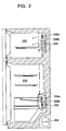
- FIG. 2 is a sectional view illustrating a cooling apparatus according to an embodiment of the present invention, in which a refrigerator is illustrated as an example of the cooling apparatus.
- the refrigerator of the present invention comprises a refrigerator compartment 210 and a freezer compartment 220.
- An evaporator 206, a fan drive motor 206a, and a fan 206b are installed in the refrigerator compartment 210.
- an evaporator 208, a fan drive motor 208a, and a fan 208b are installed in the freezer compartment 220.
- a compressor 202, a condenser 204 (see, Figure 3), the refrigerator compartment evaporator 206, and the freezer compartment evaporator 208 are connected to each other by refrigerant pipes to form a refrigeration circuit.
- a refrigerator compartment capillary tube and a freezer compartment capillary tube are installed at a position around an inlet of the refrigerator compartment evaporator 206 and at a position around an inlet of the freezer compartment evaporator 208, respectively, so as to reduce a pressure of the refrigerant, although the two capillary tubes are not illustrated in Figure 2.
- FIG 3 is a view illustrating a refrigeration circuit of the cooling apparatus illustrated in Figure 2.
- the refrigeration circuit of the cooling apparatus includes the compressor 202, the condenser 204, a first capillary tube 302, the refrigerator compartment evaporator 206, and the freezer compartment evaporator 208, which are connected to each other by refrigerant pipes so that the refrigerant flowing from the compressor 202 passes the condenser 204, the first capillary tube 302, the refrigerator compartment evaporator 206, and the freezer compartment evaporator 208, and then is returned to an inlet of the compressor 202.
- the flow of the refrigerant flowing from the condenser 204 is branched into two streams.
- the cooling apparatus further comprises a first fan motor 204a to drive a condenser fan 204b, a second fan motor 206a to drive a refrigerator compartment fan 206b, and a third fan motor 208a to drive a freezer compartment fan 208b.
- the first capillary tube 302 is used as a refrigerator compartment capillary tube. That is, the first capillary tube 302 reduces the pressure of the refrigerant flowing from the condenser 204 so that the refrigerant is easily evaporated in the refrigerator compartment evaporator 206.
- the pressure of the refrigerant passing the refrigerator compartment evaporator 206 is excessive low, the refrigerant evaporating temperature of the refrigerator compartment evaporator 206 is excessively low, so the temperature of the refrigerator compartment 210 becomes excessively and undesirably low. Under such conditions, frost is formed on the refrigerator compartment evaporator 206, thus reducing the humidity in the refrigerator compartment 210, and resulting in a low cooling capability of the refrigerator compartment 210.
- a diameter and a length of the first capillary tube 302 are determined so as to accomplish an appropriate reduction in pressure of the refrigerant, thus preventing the refrigerant evaporating temperature of the refrigerator compartment 210 from becoming excessively low.
- the second and third capillary tubes 304 and 306 are used as freezer compartment capillary tubes.
- the second capillary tube 304 is used for primarily reducing the pressure of the refrigerant so as to obtain a refrigerant evaporating temperature demanded by the freezer compartment evaporator 208.
- the third capillary tube 306 is used for secondarily reducing the pressure of the refrigerant which is primarily reduced in pressure in the second capillary tube 304, thus allowing the freezer compartment 220 to be more quickly cooled.
- resistance applied to the refrigerant in the first capillary tube 302 is designated as R2
- resistance applied to the refrigerant in the second capillary tube 304 is designated as R4
- the relation between R2 and R4 is that R2 is less than R4.
- the capillary tubes are used as expansion units to expand refrigerant.
- the expansion units of the present invention may be selected from various types of expansion devices without being limited to the capillary tubes.
- a three-way valve 308 is used as a path control unit of the cooling apparatus.
- the three-way valve 308 is connected to an outlet of the refrigerator compartment evaporator 206, an inlet of the freezer compartment evaporator 208, and a line connecting the second and third capillary tubes 304 and 306.
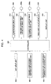
- the cooling apparatus further comprises a controller which controls the three-way valve 308 to control paths of the refrigerant flowing from the refrigerator compartment evaporator 206 or the second capillary tube 304. The mechanism and method of controlling the cooling apparatus will be described below with reference to Figure 4.
- a key input unit 404, a freezer compartment temperature sensing unit 406 and a refrigerator compartment temperature sensing unit 408 are electrically connected to input terminals of a controller 402.
- the key input unit 404 is provided with a plurality of function keys so as to input a desired operating mode and desired operating conditions of the cooling apparatus, such as temperatures demanded by the refrigerator compartment and the freezer compartment.
- the freezer compartment temperature sensing unit 406 and the refrigerator compartment temperature sensing unit 408 sense the temperatures inside the freezer compartment 220 and the refrigerator compartment 210, respectively, and output signals indicating the sensed results to the controller 402.
- a display unit 410 is connected to an output terminal of the controller 402, and displays an operating state, several input values, and temperatures of the respective compartments in the cooling apparatus.
- a compressor drive unit 412 to drive the compressor 202, a freezer compartment fan motor drive unit 414 to drive the freezer compartment fan motor 208a, a refrigerator compartment fan motor drive unit 416 to drive the refrigerator compartment fan motor 206a, and a three-way valve drive unit 418 to drive the three-way valve 308, are connected to output terminals of the controller 402.
- the controller 402 controls the three-way valve 308 to control the refrigerant paths according to a cooling mode required by the cooling apparatus.
- the controller 402 controls the refrigerant paths by selectively opening or closing first and second ports 308a and 308b, respectively, of the three-way valve 308. That is, both ports 308a and 308b may be open, both ports 308a and 308b may be closed, or one of the ports 308a and 308b may be open and the other of the ports 308a and 308b may be closed, thus forming four different refrigerant paths.
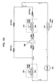
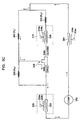
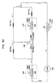
- Figures 5A through to 5D are views illustrating first, second, third, and fourth refrigerant paths, respectively, achieved in the refrigeration circuit of the cooling apparatus illustrated in Figure 3, by controlling the three-way valve.
- the arrows shown in Figures 5A through 5D denote refrigerant flowing directions.
- Figure 5A is a view illustrating a first refrigerant path, in which both the first and second ports 308a and 308b of the three-way valve 308 are open.
- the refrigerant flowing from the compressor 202 passes through the condenser 204 and flows into the first capillary tube 302, because the resistance R2 applied to the refrigerant in the first capillary tube 302 is smaller than the resistance R4 applied to the refrigerant in the second capillary tube 304. While the refrigerant passes the first capillary tube 302, the pressure of the refrigerant is reduced so that the refrigerant is expanded.
- the expanded refrigerant is evaporated in the refrigerator compartment evaporator 206 to cool the refrigerator compartment 210.
- the refrigerant flowing from the refrigerator compartment evaporator 206 passes the first and second ports 308a and 308b of the three-way valve 308, and flows into the freezer compartment evaporator 208.
- the pressure of the refrigerant flowing from the refrigerator compartment evaporator 206 is not further reduced, so the freezer compartment 220 is not cooled.
- a refrigerant evaporating temperature of the refrigerator compartment evaporator 206 is the same as a refrigerant evaporating temperature of the freezer compartment evaporator 208, thus quickly cooling the refrigerator compartment 210.
- Figure 5B is a view illustrating a second refrigerant path, in which the first port 308a is open and the second port 308b is closed.
- the refrigerant flowing from the condenser 204 passes the first capillary tube 302.
- the pressure of the refrigerant is reduced in the first capillary tube 302 so that the refrigerant is expanded.
- the expanded refrigerant is evaporated in the refrigerator compartment evaporator 206, thus cooling the refrigerator compartment 210.
- the refrigerant flowing from the refrigerator compartment evaporator 206 passes the third capillary tube 306.
- the pressure of the refrigerant flowing from the refrigerator compartment evaporator 206 is reduced once again by the third capillary tube 306, so that the refrigerant is expanded again.
- the expanded refrigerant is then evaporated in the freezer compartment evaporator 208, thus cooling the freezer compartment 220.
- the evaporating temperature of the refrigerator compartment evaporator 206 is higher than the evaporating temperature of the freezer compartment evaporator 208, so the formation of frost is reduced on the refrigerator compartment 210, thus maintaining a high percentage of humidity in the refrigerator compartment 210, and allowing food stored in the refrigerator compartment 210 to be kept fresh.
- the refrigerant pressure in the refrigerator compartment evaporator 206 is higher than the refrigerant pressure of the freezer compartment evaporator 208, the load imposed on the compressor 202 is reduced, thus enhancing the energy efficiency ratio of the cooling apparatus.
- Figure 5C is a view illustrating a third refrigerant path, in which the first port 308a is closed and the second port 308b is open.
- the refrigerant flowing from the condenser 204 flows into the second capillary tube 304 although R4 is larger than R2.
- the pressure of the refrigerant is reduced in the second capillary tube 304 so that the refrigerant is expanded.
- the expanded refrigerant flows into the freezer compartment evaporator 208 through the second port 308b.
- the refrigerant is evaporated in the freezer compartment evaporator 208, thus cooling the freezer compartment 220.
- the first port 308a When the first port 308a is closed and the second port 308b is open as shown in Figure 5C, only the freezer compartment 220 is cooled. That is, when the refrigerator compartment 210 reaches a predetermined target temperature and the temperature of the freezer compartment 220 is lower than a predetermined target point, the first port 308a of the three-way valve 308 is closed and the second port 308b of the three-way valve 308 is open, as illustrated in Figure 5C, so as to cool only the freezer compartment 220, thus allowing the freezer compartment 220 to reach its target temperature while preventing the refrigerator compartment 210 from being overly cooled.
- Figure 5D is a view illustrating a fourth refrigerant path, in which both the first and second ports 308a and 308b of the three-way valve 308 are closed.
- the refrigerant flowing from the condenser 204 is stepwisely reduced in pressure in the second and third capillary tubes 304 and 306, so that the refrigerant is expanded twice.
- the expanded refrigerant flows into the freezer compartment evaporator 208 and is evaporated in the freezer compartment evaporator 208, thus more quickly cooling only the freezer compartment 220.
- both the first and second ports 308a and 308b of the three-way valve 308 may be closed, as illustrated in Figure 5D.
- only the second port 308b may be opened, as illustrated in Figure 5C.
- a lower evaporating temperature is accomplished in the freezer compartment evaporator 208, in comparison with a case where the refrigerant is expanded by only the second capillary tube 304, as illustrated in Figure 5C, thus increasing a cooling speed of the freezer compartment 220. Therefore, only the freezer compartment 220 is more effectively and quickly cooled.
- the present invention may be applied to all types of apparatuses, including refrigerators, air conditioners, etc., operated according to a heat-exchanging process via the evaporation of a refrigerant.
- the present invention provides a cooling apparatus which is capable of achieving various refrigeration cycles by controlling refrigerant paths, thus accomplishing optimum refrigerant evaporating temperatures demanded by a refrigerator compartment evaporator and a freezer compartment evaporator, and allowing the refrigerator compartment and the freezer compartment to be selectively cooled, therefore increasing cooling efficiency and cooling speed of the cooling apparatus.
Landscapes
- Engineering & Computer Science (AREA)
- Physics & Mathematics (AREA)
- Mechanical Engineering (AREA)
- Thermal Sciences (AREA)
- General Engineering & Computer Science (AREA)
- Chemical & Material Sciences (AREA)
- Combustion & Propulsion (AREA)
- Devices That Are Associated With Refrigeration Equipment (AREA)
Applications Claiming Priority (2)
| Application Number | Priority Date | Filing Date | Title |
|---|---|---|---|
| KR1020020068499A KR100638103B1 (ko) | 2002-11-06 | 2002-11-06 | 냉각 장치 |
| KR2002068499 | 2002-11-06 |
Publications (3)
| Publication Number | Publication Date |
|---|---|
| EP1418392A2 true EP1418392A2 (de) | 2004-05-12 |
| EP1418392A3 EP1418392A3 (de) | 2004-07-28 |
| EP1418392B1 EP1418392B1 (de) | 2010-10-13 |
Family
ID=32105670
Family Applications (1)
| Application Number | Title | Priority Date | Filing Date |
|---|---|---|---|
| EP03252857A Expired - Lifetime EP1418392B1 (de) | 2002-11-06 | 2003-05-07 | Kühlvorrichtung |
Country Status (5)
| Country | Link |
|---|---|
| US (1) | US6758053B2 (de) |
| EP (1) | EP1418392B1 (de) |
| KR (1) | KR100638103B1 (de) |
| CN (1) | CN1245601C (de) |
| DE (1) | DE60334519D1 (de) |
Cited By (1)
| Publication number | Priority date | Publication date | Assignee | Title |
|---|---|---|---|---|
| ITTO20130143A1 (it) * | 2013-02-21 | 2014-08-22 | Indesit Co Spa | Metodo di controllo di un apparecchio refrigerante |
Families Citing this family (14)
| Publication number | Priority date | Publication date | Assignee | Title |
|---|---|---|---|---|
| KR100504478B1 (ko) * | 2002-11-09 | 2005-08-03 | 엘지전자 주식회사 | 공기조화기용 실내열교환기 |
| EP1781998B1 (de) * | 2004-08-18 | 2009-06-24 | Arçelik Anonim Sirketi | Kühlvorrichtung |
| EP1780484A1 (de) * | 2004-08-19 | 2007-05-02 | Hisense Group Co., Ltd. | Verbund-kühlschrank mit einem multizyklus-kühlsystem und steuerverfahren dafür |
| US7334425B1 (en) * | 2004-11-08 | 2008-02-26 | Emed Johnson | Rotative tri-module refrigeration unit |
| DE102005045585A1 (de) * | 2005-05-11 | 2006-11-16 | Liebherr-Hausgeräte Ochsenhausen GmbH | Kühl- und/oder Gefriergerät sowie Verfahren zur Steuerung desselben |
| US8794026B2 (en) | 2008-04-18 | 2014-08-05 | Whirlpool Corporation | Secondary cooling apparatus and method for a refrigerator |
| KR101666428B1 (ko) * | 2009-12-22 | 2016-10-17 | 삼성전자주식회사 | 냉장고 및 그 운전제어방법 |
| KR102213634B1 (ko) * | 2013-06-27 | 2021-02-08 | 엘지전자 주식회사 | 냉장고 및 그 운전방법 |
| CN104596198A (zh) * | 2015-01-22 | 2015-05-06 | 刘雄 | 无霜冰箱控制方法 |
| US10544979B2 (en) | 2016-12-19 | 2020-01-28 | Whirlpool Corporation | Appliance and method of controlling the appliance |
| CN109059395B (zh) * | 2018-06-20 | 2021-01-26 | 合肥美的电冰箱有限公司 | 冰箱及冰箱的控制方法 |
| CN109059326A (zh) * | 2018-08-16 | 2018-12-21 | 海信(山东)冰箱有限公司 | 一种冰箱制冷系统及控制方法 |
| KR102287961B1 (ko) * | 2020-08-07 | 2021-08-10 | 엘지전자 주식회사 | 냉장고 및 그 제어방법 |
| CN112797518A (zh) * | 2020-12-28 | 2021-05-14 | 珠海格力电器股份有限公司 | 空调冰箱组件和空调冰箱一体机 |
Family Cites Families (13)
| Publication number | Priority date | Publication date | Assignee | Title |
|---|---|---|---|---|
| JPS5236354A (en) * | 1975-09-17 | 1977-03-19 | Matsushita Electric Ind Co Ltd | Refrigerant circuit |
| DE2553562C3 (de) * | 1975-11-28 | 1978-05-18 | Danfoss A/S, Nordborg (Daenemark) | Kompressor-Kälteanlage |
| JPS5319859U (de) * | 1976-07-30 | 1978-02-20 | ||
| US4227379A (en) * | 1978-02-23 | 1980-10-14 | Tokyo Shibaura Denki Kabushiki Kaisha | Cooling apparatus |
| JPS5975670U (ja) * | 1982-11-10 | 1984-05-22 | 松下冷機株式会社 | 冷蔵庫 |
| JPS59164860A (ja) * | 1983-03-09 | 1984-09-18 | 株式会社東芝 | 冷蔵庫の冷凍サイクル |
| JPS604774A (ja) * | 1983-06-22 | 1985-01-11 | 株式会社東芝 | 冷蔵庫 |
| JPH071128B2 (ja) * | 1987-02-27 | 1995-01-11 | 株式会社東芝 | 冷蔵庫用冷凍サイクル |
| JPH085172A (ja) * | 1994-06-22 | 1996-01-12 | Matsushita Refrig Co Ltd | 冷凍冷蔵庫の冷却装置 |
| US5896753A (en) | 1996-10-18 | 1999-04-27 | Lg Electronics Inc. | Freezing cycle apparatus having quick freezing and thawing functions |
| TW446106U (en) * | 1998-02-20 | 2001-07-11 | Matsushita Refrigeration Co Lt | Refrigerator having a cooler mounted in each of a refrigerator compartment and a freezer compartment |
| JP3630632B2 (ja) * | 2000-12-12 | 2005-03-16 | 株式会社東芝 | 冷蔵庫 |
| KR20040020618A (ko) * | 2002-08-31 | 2004-03-09 | 삼성전자주식회사 | 냉장고 |
-
2002
- 2002-11-06 KR KR1020020068499A patent/KR100638103B1/ko not_active Expired - Fee Related
-
2003
- 2003-04-15 US US10/413,407 patent/US6758053B2/en not_active Expired - Fee Related
- 2003-05-07 CN CNB031306926A patent/CN1245601C/zh not_active Expired - Fee Related
- 2003-05-07 EP EP03252857A patent/EP1418392B1/de not_active Expired - Lifetime
- 2003-05-07 DE DE60334519T patent/DE60334519D1/de not_active Expired - Lifetime
Cited By (2)
| Publication number | Priority date | Publication date | Assignee | Title |
|---|---|---|---|---|
| ITTO20130143A1 (it) * | 2013-02-21 | 2014-08-22 | Indesit Co Spa | Metodo di controllo di un apparecchio refrigerante |
| EP2770282A1 (de) * | 2013-02-21 | 2014-08-27 | Indesit Company S.p.A. | Verfahren zur Regelung einer Kühlanlage |
Also Published As
| Publication number | Publication date |
|---|---|
| KR100638103B1 (ko) | 2006-10-25 |
| CN1499161A (zh) | 2004-05-26 |
| DE60334519D1 (de) | 2010-11-25 |
| CN1245601C (zh) | 2006-03-15 |
| EP1418392B1 (de) | 2010-10-13 |
| EP1418392A3 (de) | 2004-07-28 |
| KR20040040153A (ko) | 2004-05-12 |
| US6758053B2 (en) | 2004-07-06 |
| US20040083746A1 (en) | 2004-05-06 |
Similar Documents
| Publication | Publication Date | Title |
|---|---|---|
| EP1394481B1 (de) | Kühlschrank | |
| KR0182758B1 (ko) | 고효율 독립냉각 싸이클을 가지는 냉장고의 제어방법 | |
| US7137266B2 (en) | Time division multi-cycle type cooling apparatus and method for controlling the same | |
| US7441413B2 (en) | Refrigerator and control method thereof | |
| EP1418392A2 (de) | Kühlvorrichtung | |
| US20040112082A1 (en) | Regfrigerating device | |
| KR100297026B1 (ko) | 냉장고용냉동사이클장치 | |
| KR101140711B1 (ko) | 냉장고 및 그 운전제어방법 | |
| KR102237596B1 (ko) | 냉장고 및 그 제어방법 | |
| US20060236707A1 (en) | Refrigerator controlling method | |
| US20070068193A1 (en) | Refrigerator and method for controlling operation of the same | |
| JP2002081817A (ja) | 冷蔵庫 | |
| JPH11148761A (ja) | 冷蔵庫 | |
| JPS6350628B2 (de) | ||
| KR102211202B1 (ko) | 냉장고 및 그 제어방법 | |
| JP2004028370A (ja) | 冷凍冷蔵庫 | |
| JP2005134080A (ja) | 冷蔵庫 | |
| JP2012082984A (ja) | 冷蔵庫 | |
| KR20210040018A (ko) | 냉장고 및 그 제어방법 | |
| KR20200106868A (ko) | 냉장고 | |
| KR102246351B1 (ko) | 냉장고 | |
| JPH0534026A (ja) | 冷凍サイクル装置 | |
| KR100747844B1 (ko) | 냉장고 | |
| JPS6350630B2 (de) | ||
| AU2005201546B2 (en) | Refrigerator and control method thereof |
Legal Events
| Date | Code | Title | Description |
|---|---|---|---|
| PUAI | Public reference made under article 153(3) epc to a published international application that has entered the european phase |
Free format text: ORIGINAL CODE: 0009012 |
|
| 17P | Request for examination filed |
Effective date: 20030527 |
|
| AK | Designated contracting states |
Kind code of ref document: A2 Designated state(s): AT BE BG CH CY CZ DE DK EE ES FI FR GB GR HU IE IT LI LU MC NL PT RO SE SI SK TR |
|
| AX | Request for extension of the european patent |
Extension state: AL LT LV MK |
|
| PUAL | Search report despatched |
Free format text: ORIGINAL CODE: 0009013 |
|
| AK | Designated contracting states |
Kind code of ref document: A3 Designated state(s): AT BE BG CH CY CZ DE DK EE ES FI FR GB GR HU IE IT LI LU MC NL PT RO SE SI SK TR |
|
| AX | Request for extension of the european patent |
Extension state: AL LT LV MK |
|
| AKX | Designation fees paid |
Designated state(s): DE FR GB |
|
| GRAP | Despatch of communication of intention to grant a patent |
Free format text: ORIGINAL CODE: EPIDOSNIGR1 |
|
| GRAS | Grant fee paid |
Free format text: ORIGINAL CODE: EPIDOSNIGR3 |
|
| GRAA | (expected) grant |
Free format text: ORIGINAL CODE: 0009210 |
|
| AK | Designated contracting states |
Kind code of ref document: B1 Designated state(s): DE FR GB |
|
| REG | Reference to a national code |
Ref country code: GB Ref legal event code: FG4D |
|
| REF | Corresponds to: |
Ref document number: 60334519 Country of ref document: DE Date of ref document: 20101125 Kind code of ref document: P |
|
| PLBE | No opposition filed within time limit |
Free format text: ORIGINAL CODE: 0009261 |
|
| STAA | Information on the status of an ep patent application or granted ep patent |
Free format text: STATUS: NO OPPOSITION FILED WITHIN TIME LIMIT |
|
| 26N | No opposition filed |
Effective date: 20110714 |
|
| REG | Reference to a national code |
Ref country code: DE Ref legal event code: R097 Ref document number: 60334519 Country of ref document: DE Effective date: 20110714 |
|
| REG | Reference to a national code |
Ref country code: FR Ref legal event code: PLFP Year of fee payment: 13 |
|
| PGFP | Annual fee paid to national office [announced via postgrant information from national office to epo] |
Ref country code: DE Payment date: 20150422 Year of fee payment: 13 |
|
| PGFP | Annual fee paid to national office [announced via postgrant information from national office to epo] |
Ref country code: FR Payment date: 20150422 Year of fee payment: 13 |
|
| PGFP | Annual fee paid to national office [announced via postgrant information from national office to epo] |
Ref country code: GB Payment date: 20160421 Year of fee payment: 14 |
|
| REG | Reference to a national code |
Ref country code: DE Ref legal event code: R119 Ref document number: 60334519 Country of ref document: DE |
|
| REG | Reference to a national code |
Ref country code: FR Ref legal event code: ST Effective date: 20170131 |
|
| PG25 | Lapsed in a contracting state [announced via postgrant information from national office to epo] |
Ref country code: DE Free format text: LAPSE BECAUSE OF NON-PAYMENT OF DUE FEES Effective date: 20161201 Ref country code: FR Free format text: LAPSE BECAUSE OF NON-PAYMENT OF DUE FEES Effective date: 20160531 |
|
| GBPC | Gb: european patent ceased through non-payment of renewal fee |
Effective date: 20170507 |
|
| PG25 | Lapsed in a contracting state [announced via postgrant information from national office to epo] |
Ref country code: GB Free format text: LAPSE BECAUSE OF NON-PAYMENT OF DUE FEES Effective date: 20170507 |