EP1419426B1 - Regulateur de pression - Google Patents
Regulateur de pression Download PDFInfo
- Publication number
- EP1419426B1 EP1419426B1 EP02766106A EP02766106A EP1419426B1 EP 1419426 B1 EP1419426 B1 EP 1419426B1 EP 02766106 A EP02766106 A EP 02766106A EP 02766106 A EP02766106 A EP 02766106A EP 1419426 B1 EP1419426 B1 EP 1419426B1
- Authority
- EP
- European Patent Office
- Prior art keywords
- cover
- pressure
- valve body
- valve
- chamber
- Prior art date
- Legal status (The legal status is an assumption and is not a legal conclusion. Google has not performed a legal analysis and makes no representation as to the accuracy of the status listed.)
- Expired - Lifetime
Links
- 239000012530 fluid Substances 0.000 claims abstract description 55
- 238000004891 communication Methods 0.000 claims description 4
- 230000001105 regulatory effect Effects 0.000 abstract description 2
- 230000007423 decrease Effects 0.000 abstract 1
- 230000003247 decreasing effect Effects 0.000 abstract 1
- 238000010276 construction Methods 0.000 description 6
- 239000000463 material Substances 0.000 description 4
- 230000006870 function Effects 0.000 description 2
- 239000007788 liquid Substances 0.000 description 2
- LFQSCWFLJHTTHZ-UHFFFAOYSA-N Ethanol Chemical compound CCO LFQSCWFLJHTTHZ-UHFFFAOYSA-N 0.000 description 1
- 239000000853 adhesive Substances 0.000 description 1
- 230000001070 adhesive effect Effects 0.000 description 1
- 238000013459 approach Methods 0.000 description 1
- 230000001276 controlling effect Effects 0.000 description 1
- 238000010168 coupling process Methods 0.000 description 1
- 239000013536 elastomeric material Substances 0.000 description 1
- 230000001976 improved effect Effects 0.000 description 1
- 230000002401 inhibitory effect Effects 0.000 description 1
- 238000009434 installation Methods 0.000 description 1
- 230000013011 mating Effects 0.000 description 1
- 229920001296 polysiloxane Polymers 0.000 description 1
- 229920000915 polyvinyl chloride Polymers 0.000 description 1
- 239000004800 polyvinyl chloride Substances 0.000 description 1
Images


Classifications
-
- G—PHYSICS
- G05—CONTROLLING; REGULATING
- G05D—SYSTEMS FOR CONTROLLING OR REGULATING NON-ELECTRIC VARIABLES
- G05D16/00—Control of fluid pressure
- G05D16/04—Control of fluid pressure without auxiliary power
- G05D16/06—Control of fluid pressure without auxiliary power the sensing element being a flexible membrane, yielding to pressure, e.g. diaphragm, bellows, capsule
- G05D16/08—Control of liquid pressure
-
- G—PHYSICS
- G05—CONTROLLING; REGULATING
- G05D—SYSTEMS FOR CONTROLLING OR REGULATING NON-ELECTRIC VARIABLES
- G05D16/00—Control of fluid pressure
- G05D16/04—Control of fluid pressure without auxiliary power
- G05D16/06—Control of fluid pressure without auxiliary power the sensing element being a flexible membrane, yielding to pressure, e.g. diaphragm, bellows, capsule
- G05D16/063—Control of fluid pressure without auxiliary power the sensing element being a flexible membrane, yielding to pressure, e.g. diaphragm, bellows, capsule the sensing element being a membrane
- G05D16/0644—Control of fluid pressure without auxiliary power the sensing element being a flexible membrane, yielding to pressure, e.g. diaphragm, bellows, capsule the sensing element being a membrane the membrane acting directly on the obturator
- G05D16/0647—Control of fluid pressure without auxiliary power the sensing element being a flexible membrane, yielding to pressure, e.g. diaphragm, bellows, capsule the sensing element being a membrane the membrane acting directly on the obturator using one membrane without spring
-
- Y—GENERAL TAGGING OF NEW TECHNOLOGICAL DEVELOPMENTS; GENERAL TAGGING OF CROSS-SECTIONAL TECHNOLOGIES SPANNING OVER SEVERAL SECTIONS OF THE IPC; TECHNICAL SUBJECTS COVERED BY FORMER USPC CROSS-REFERENCE ART COLLECTIONS [XRACs] AND DIGESTS
- Y10—TECHNICAL SUBJECTS COVERED BY FORMER USPC
- Y10S—TECHNICAL SUBJECTS COVERED BY FORMER USPC CROSS-REFERENCE ART COLLECTIONS [XRACs] AND DIGESTS
- Y10S137/00—Fluid handling
- Y10S137/903—Rubber valve springs
-
- Y—GENERAL TAGGING OF NEW TECHNOLOGICAL DEVELOPMENTS; GENERAL TAGGING OF CROSS-SECTIONAL TECHNOLOGIES SPANNING OVER SEVERAL SECTIONS OF THE IPC; TECHNICAL SUBJECTS COVERED BY FORMER USPC CROSS-REFERENCE ART COLLECTIONS [XRACs] AND DIGESTS
- Y10—TECHNICAL SUBJECTS COVERED BY FORMER USPC
- Y10T—TECHNICAL SUBJECTS COVERED BY FORMER US CLASSIFICATION
- Y10T137/00—Fluid handling
- Y10T137/0318—Processes
- Y10T137/0324—With control of flow by a condition or characteristic of a fluid
- Y10T137/0379—By fluid pressure
-
- Y—GENERAL TAGGING OF NEW TECHNOLOGICAL DEVELOPMENTS; GENERAL TAGGING OF CROSS-SECTIONAL TECHNOLOGIES SPANNING OVER SEVERAL SECTIONS OF THE IPC; TECHNICAL SUBJECTS COVERED BY FORMER USPC CROSS-REFERENCE ART COLLECTIONS [XRACs] AND DIGESTS
- Y10—TECHNICAL SUBJECTS COVERED BY FORMER USPC
- Y10T—TECHNICAL SUBJECTS COVERED BY FORMER US CLASSIFICATION
- Y10T137/00—Fluid handling
- Y10T137/0318—Processes
- Y10T137/0396—Involving pressure control
-
- Y—GENERAL TAGGING OF NEW TECHNOLOGICAL DEVELOPMENTS; GENERAL TAGGING OF CROSS-SECTIONAL TECHNOLOGIES SPANNING OVER SEVERAL SECTIONS OF THE IPC; TECHNICAL SUBJECTS COVERED BY FORMER USPC CROSS-REFERENCE ART COLLECTIONS [XRACs] AND DIGESTS
- Y10—TECHNICAL SUBJECTS COVERED BY FORMER USPC
- Y10T—TECHNICAL SUBJECTS COVERED BY FORMER US CLASSIFICATION
- Y10T137/00—Fluid handling
- Y10T137/0318—Processes
- Y10T137/0402—Cleaning, repairing, or assembling
- Y10T137/0491—Valve or valve element assembling, disassembling, or replacing
- Y10T137/0497—Fluid actuated or retarded
-
- Y—GENERAL TAGGING OF NEW TECHNOLOGICAL DEVELOPMENTS; GENERAL TAGGING OF CROSS-SECTIONAL TECHNOLOGIES SPANNING OVER SEVERAL SECTIONS OF THE IPC; TECHNICAL SUBJECTS COVERED BY FORMER USPC CROSS-REFERENCE ART COLLECTIONS [XRACs] AND DIGESTS
- Y10—TECHNICAL SUBJECTS COVERED BY FORMER USPC
- Y10T—TECHNICAL SUBJECTS COVERED BY FORMER US CLASSIFICATION
- Y10T137/00—Fluid handling
- Y10T137/7722—Line condition change responsive valves
- Y10T137/7781—With separate connected fluid reactor surface
- Y10T137/7793—With opening bias [e.g., pressure regulator]
- Y10T137/7822—Reactor surface closes chamber
- Y10T137/7823—Valve head in inlet chamber
- Y10T137/7825—Rectilinear valve stem rigid with reactor surface
-
- Y—GENERAL TAGGING OF NEW TECHNOLOGICAL DEVELOPMENTS; GENERAL TAGGING OF CROSS-SECTIONAL TECHNOLOGIES SPANNING OVER SEVERAL SECTIONS OF THE IPC; TECHNICAL SUBJECTS COVERED BY FORMER USPC CROSS-REFERENCE ART COLLECTIONS [XRACs] AND DIGESTS
- Y10—TECHNICAL SUBJECTS COVERED BY FORMER USPC
- Y10T—TECHNICAL SUBJECTS COVERED BY FORMER US CLASSIFICATION
- Y10T137/00—Fluid handling
- Y10T137/7722—Line condition change responsive valves
- Y10T137/7837—Direct response valves [i.e., check valve type]
- Y10T137/7869—Biased open
- Y10T137/7871—Weight biased
-
- Y—GENERAL TAGGING OF NEW TECHNOLOGICAL DEVELOPMENTS; GENERAL TAGGING OF CROSS-SECTIONAL TECHNOLOGIES SPANNING OVER SEVERAL SECTIONS OF THE IPC; TECHNICAL SUBJECTS COVERED BY FORMER USPC CROSS-REFERENCE ART COLLECTIONS [XRACs] AND DIGESTS
- Y10—TECHNICAL SUBJECTS COVERED BY FORMER USPC
- Y10T—TECHNICAL SUBJECTS COVERED BY FORMER US CLASSIFICATION
- Y10T137/00—Fluid handling
- Y10T137/7722—Line condition change responsive valves
- Y10T137/7837—Direct response valves [i.e., check valve type]
- Y10T137/7904—Reciprocating valves
- Y10T137/7922—Spring biased
-
- Y—GENERAL TAGGING OF NEW TECHNOLOGICAL DEVELOPMENTS; GENERAL TAGGING OF CROSS-SECTIONAL TECHNOLOGIES SPANNING OVER SEVERAL SECTIONS OF THE IPC; TECHNICAL SUBJECTS COVERED BY FORMER USPC CROSS-REFERENCE ART COLLECTIONS [XRACs] AND DIGESTS
- Y10—TECHNICAL SUBJECTS COVERED BY FORMER USPC
- Y10T—TECHNICAL SUBJECTS COVERED BY FORMER US CLASSIFICATION
- Y10T137/00—Fluid handling
- Y10T137/8158—With indicator, register, recorder, alarm or inspection means
- Y10T137/8225—Position or extent of motion indicator
-
- Y—GENERAL TAGGING OF NEW TECHNOLOGICAL DEVELOPMENTS; GENERAL TAGGING OF CROSS-SECTIONAL TECHNOLOGIES SPANNING OVER SEVERAL SECTIONS OF THE IPC; TECHNICAL SUBJECTS COVERED BY FORMER USPC CROSS-REFERENCE ART COLLECTIONS [XRACs] AND DIGESTS
- Y10—TECHNICAL SUBJECTS COVERED BY FORMER USPC
- Y10T—TECHNICAL SUBJECTS COVERED BY FORMER US CLASSIFICATION
- Y10T137/00—Fluid handling
- Y10T137/8158—With indicator, register, recorder, alarm or inspection means
- Y10T137/8326—Fluid pressure responsive indicator, recorder or alarm
Definitions
- This invention relates to fluid pressure regulators, and particularly to regulators well suited for controlling the output pressure of elastomeric balloon or mechanical pumps. More specifically, the present invention relates to a variable fluid pressure regulator which allows for convenient adjustment of fluid outlet pressure.
- Pressure regulators that reduce or cut off inlet flow of a fluid when the outlet pressure starts to exceed a predetermined maximum and that open or increase flow when the outlet pressure has been sufficiently reduced are wen known in the art.
- Such regulators generally include a coil spring that biases a valve member open, and a pressure-sensing element responsive to excess inlet pressure which closes the valve member.
- increasing liquid pressure compresses the spring to force the valve member towards a valve seat.
- liquid flow through the regulator becomes more restricted.
- the valve member moves away from the valve seat and flow increases. This cycle is rapidly repeated over and over to maintain the output pressure at the desired setting.
- a goal of preferred embodiments is to provide a simplified pressure regulator having fewer parts thereby making it easier to assemble, less expensive and less likely to break.
- a resilient diaphragm is employed that by itself controls input flow and regulates output pressure.
- the diaphragm is made of an elasticomeric material, and is designed not only to act as a diaphragm, but also to replace the pressure sensing spring and the valve seat spring.
- the diaphragm is manufactured to be flat, however, after installation into the regulator, an adjuster is moved to deflect the diaphragm.
- the amount of deflection corresponds with the desired outlet fluid pressure.
- the diaphragm resists deflection when outlet pressure is less than the desired level, but flexes towards a closed position when the outlet pressure exceeds this level.
- this diaphragm uniquely has the additional advantage of functioning as a spring without having any of the disadvantages.
- a preferred embodiment of the fluid pressure regulator includes a cover, which engages the adjuster such that rotation of the cover results in rotation of the adjuster to deflect the diaphragm and adjust the fluid outlet pressure, as described above.
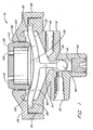
- the pro-set pressure regulator indicated generally by the numeral 10, comprises a base 15, a resilient wall or diaphragm 20, a retainer 25, and an initial adjuster in the form of a cap 30.
- the base 15 has an inlet 35 where fluid is introduced into the regulator 10 and an outlet 40 where the fluid exits at the desired pressure.
- a central, axial passage 45 extends through the base 15, and is in fluid communication with the inlet 35.
- the diameter of the open end at the top of the passage 45 which is smaller than the lower portion forms a valve seat 50.
- a plug 55 closes the lower end of the passage.
- the top surface of the base 15 is concave and forms the lower boundary of a fluid pressure-sensing chamber 60.
- the perimeter of the top surface of the base member has an angled, annular shoulder 65 which defines a seating and gripping surface for the diaphragm 20.
- the shoulder 65 has an externally threaded lip 70 which mates with interior threads on the retainer 25, which is generally ring shaped.
- the outlet conduit 40 in fluid communication with the chamber 60 extends from the top surface of the base 15 to an exterior surface of the base 15.
- the diaphragm 20 is a general circular, preferably generally flat member which has an outer annular portion clamped between the base shoulder 65 and a flat annular surface 90 on the retainer 25 to seal that area. This causes the bottom surface of the diaphragm to form the upper boundary of the pressure-sensing chamber 60.
- the diaphragm is preferably made of an elastomeric material, such as silicone so that it will be responsive to fluid pressure changes in the chamber 60 and has a significant "memory" so that it is self-restoring.
- an integral valve stem 75 which extends axially through the chamber 60 and into the passage 45.
- a valve element 80 on the lower end of the valve stem is positioned in the passage 45 to cooperate with the valve seat 50.
- valve element 80 is preferably ball-shaped as illustrated, but may be in the form of a disk or other suitable shape that win property mate with the valve seat.
- valve element 80 may be lubricated with alcohol to enable it to be pushed through the valve seat into the passage 45.
- the retainer 25 may be ultrasonically welded to the base 15 if desired.
- An annular area 95 of the retainer 25 slopes upwardly, and inwardly to an interiorly threaded collar 105, which is part of the retainer.
- the adjuster cap 30 has a flat upper wall 110 and a cylindrical flange 115 extending downward into the collar 105. The exterior surface of the flange 115 is threaded to mate with the threads of the collar 105.
- the cap 30 is adjusted so that its lower annular end contacts the top surface of the diaphragm 20.
- the circular, central section of the diaphragm which is bounded by the cylindrical flange 120, is responsive to fluid pressure in the chamber 60.
- the loading by the adjusting cap 30 pushes the diaphragm 20 downward, thereby unseating the valve element 80, as shown in the drawing.
- the adjuster may also be in sliding or cam-like engagement with the retainer.
- the upper surface of the diaphragm 20 and the initial adjusting cap 30 form an upper interior space 130 that is separated from the pressure-sensing chamber 60 by the diaphragm 20. Vents 125 extend through the flat surface 110 of the adjusting cap 30 to prevent pressure build-up in the upper interior space 130, and to facilitate turning the adjuster cap 30 when setting the desired pressure.
- the base 15, plug 55, adjusting cap 30, and retainer 25 are preferably made of polyvinyl chloride, but may be made of other durable, inexpensive materials known to those of ordinary skill in the art.
- the valve member 80 When the diaphragm 20 is assembled within the pressure regulator 10, between the angled shoulder 65 of the base 15 and the flat surface 90 of the retainer 25, the valve member 80 is seated in a sealed closed position. After a pressure source is attached to the inlet 35, the cap 30 is advanced against the diaphragm causing the annular tip of the cap flange 115 to deflect the diaphragm 20, thereby unseating the valve element 80 from the valve seat 50. While the valve element 80 is unseated, fluid travels through the inlet 35 and the valve seat 50, flows into the fluid pressure-sensing chamber 60, and out through outlet 40. The cap is adjusted until the desired outlet pressure is attained. For a preset pressure device, a suitable adhesive or the like is applied to the threads at 115 to prevent changes in the output pressure setting.
- diaphragm 20 When the pressure of the fluid in the chamber 60 exerts a force against the bottom of the diaphragm 20 greater than the desired value initially set by the adjusting cap 30, a force imbalance occurs. The force of the fluid in the chamber 60 pushes the resilient central section of the diaphragm 20 upward causing the valve member 80 to move in a flow-reducing or flow stopping direction towards the valve seat 50. When the outlet pressure drops below the desired level, the resilient diaphragm central section moves the valve member 80 away from the valve seat 50 and fluid flow into the chamber 60 increases. The resiliency of diaphragm 20 provides its central section the self-restoring flexibility to respond to the pressure of the fluid in the fluid pressure-sensing chamber 60. Consequently, diaphragm 20 is an active member responsive to pressure changes without the need for a conventional spring.
- the valve stem and the valve may be made of the same material as the diaphragm 20 and the valve member 80, and may be made as a one piece unit.
- a valve stem 75 made from a material stiffer than that used to make the diaphragm 20 is better able to maintain a constant pressure over a wider range of input pressures.
- a rigid pin (not shown) may be inserted into the valve stem 75, after the diaphragm 20 is assembled into the valve body but before the adjusting cap 30 is installed.
- the cross section of the valve stem 75 may be increased over part or all of its length to increase stiffness.
- the valve stem may be a completely separate part that links a separate valve element to the diaphragm.
- the pressure regulator is useful in many applications but is particularly suited to control the output pressure of elastomeric balloon or other mechanical pumps.
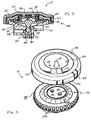
- FIGS 2-4 illustrate an additional embodiment of a fluid pressure regulator, indicated generally by the reference numeral 10'.
- the pressure regulator 10' is similar in construction and function to the pressure regulator 10 of Figure 1. Accordingly, like reference numerals will be used to denote like components, except that a (') will be added.
- pressure regulator 10' comprises a valve body including a base 15' and a retainer 25', a resilient wall or diaphragm 20', and an adjuster in the form of a cap 30'.
- the base 15' has an inlet 35' where fluid is introduced into the regulator 10' and an outlet 40' where the fluid exits at the desired . pressure.
- a central, axial passage 45' extends through the base 15', and is in fluid communication with the inlet 35'.
- the diameter of the open end at the top of the passage 45' which is smaller than the lower portion, forms a valve 50'.
- a plug 55' closes the lower end of the passage.
- the diaphragm 20' of the present pressure regulator 10' is clamped between the base 15' and the retainer 25'. Therefore, the bottom surface of the diaphragm 20' forms the upper boundary of the pressure sensing chamber 60'. An upper surface of the base 15' forms the lower boundary of the pressure sensing chamber 60'.
- an integral valve stem 75' which extends axially through the chamber 60' and into the passage 45'.
- a valve element 80' on the lower end of the valve stem is positioned in the passage 45' to cooperate with the valve seat 50'.
- the adjuster cap 30' of the present pressure regulator 10' is threadably engaged within a central portion of the retainer 25'.
- the adjuster 30' may be advanced or retracted relative to the retainer 25' such that a lower annular end 120' contacts the top surface of the diaphragm 20'. Advancing or retracting the adjuster 30' alters the force necessary to close the valve element 80' against the valve seat 50', thereby adjusting the fluid outlet pressure of the pressure regulator 10', as described above with respect to the embodiment of Figure 1.
- the pressure regulator 10' of Figures 2-4 additionally comprises a cover 150.
- the cover 150 is rotatably supported on the retainer 25' and engages the adjuster 30' such that the adjuster 30' is fixed for rotation therewith.
- rotation of the cover 150 results in corresponding rotation of the adjuster 30' such that the deflection of the diaphragm 20' is altered, thereby adjusting the fluid outlet pressure.
- the cover 150 preferably includes a plurality of flexible lock tabs 152.
- the lack tabs 152 engage the retainer 25' to hold the cover 150 in a substantially fixed axial relationship with the retainer 25' while allowing rotation with respect thereto.
- Each lock tab 152 includes a substantially transversely extending lock surface 154 configured to engage a retaining surface 156 of the retainer 25'.
- the retaining surface 156 may be a transversely extending uninterrupted annular surface. However, the retaining surface 156 may also include a series of interrupted surfaces, preferably with the interruptions being less than a width of any one of the flexible lock tabs 152.
- the illustrated pressure regulator 10' includes four, equally spaced lock tabs 152 ( Figure 4), however, a lesser or greater number of lock tabs 156 may be used.
- the lock tabs 152 and retaining surface 156 construction allow assembly of the cover 150 to the retainer 25' without the use of tools or additional fasteners.
- other suitable coupling methods may also be used.
- the cover 150 includes a pair of downwardly extending shafts or pins 157 which engage vent holes 125' of the adjuster cap 30'.
- the shafts 157 may be of a smaller diameter than that of the vent holes 125' such that pressure build-up in the upper chamber 130' is avoided.
- the pair of shafts 157 fix the adjuster cap 30' for rotation with the cover 150, while simultaneously allowing the adjuster cap 30' to move axially with respect to the cover 150 by sliding on the shafts 157.
- the adjuster cap 30' also rotates, due to its engagement with the cover 150 via the shafts 157, and moves axially with respect to the cover 150, due to its threaded engagement with the retainer 25'.
- the pressure regulator 10' also includes a catch, or detent, mechanism 158 arranged for locating the cover 150 in a desired angular position with respect to the retainer 25'.
- Each of a plurality of recesses 160 define a plurality of angular positions relative to the base 15'.
- the cover 150 includes a depending flexible tab 162 adjacent the cover periphery.
- the tab 162 includes an inwardly extending projection 164 ( Figure 4).
- the illustrated projection 164 is hemispherical in shape and each of the recesses 160 are substantial semi-cylindrical in shape. However, other suitable mating shapes may also be used, as can be determined by one of skill in the art
- the catch mechanism 158 is constructed such that the projection 164 is biased into engagement with a recess 160 by the inherent biasing force of the flexible tab 162.
- the cover 150 and thus the adjuster cap 30' are held in one of the annular positions defined by the plurality of recesses 160.
- the projection 164 is disengaged from its current recess 160 and moves into engagement with the next adjacent recess 160 in the direction of rotation of the cover 150.
- the inherent biasing force of the flexible tab 162 is such that a caregiver and/or patient may rotate the cover 150 by hand, while also inhibiting undesired rotation of the cover 150 due to vibrations or inadvertent contact.
- rotation of the cover 150 results in rotation of the adjuster cap 30' which, in turn, alters the deflection of the flexible diaphragm member 20'.
- the outlet fluid pressure is influenced by the deflection of the flexible diaphragm member 20'. Accordingly, the pressure regulator 10' allows a caregiver and/or patient to easily adjust the fluid outlet pressure to a desired value.
- the fluid pressure regulator 10' includes an indicator arrangement 166, which correlates the angular position of the cover 150 with a resulting fluid outlet pressure.
- the caregiver is able to adjust the variable pressure regulator 10' to a proper outlet pressure for a specific fluid being dispensed.
- the illustrated indicator arrangement 166 comprises an annular scale 168 on the retainer 25'.
- a reference indicia 170 is provided on the cover 150 and, when the cover 150 is assembled to the retainer 25', is aligned such that at least a portion of the scale 168 is indicated by the reference indicia 170.
- the reference indicia 170 comprises a window 172 and an arrow 174.
- the window 172 is sized and shaped preferably to display one demarcation of the scale 168.
- the arrow 174 allows for rapid identification of the location of the window 172, and may or may not be provided.
- the scale 168 of the illustrated embodiment is an index scale, which provides a relative indication of outlet pressure.
- each range of the index scale 168 may correspond to a predetermined value, or a range of values, for the fluid outlet pressure.
- the scale 168 may provide actual fluid pressure outlet values.
- the scale 168 may be provided on the cover 150 and the reference indicia 170 may be located on the retainer 25', or possibly the base 15'.
- the reference indicia 170 may comprise a projection and/or colored region of the retainer 25' or base 15'.
- other suitable arrangements for indicating a value on a scale may also be used. As such, it is not intended for the indicator arrangement 166 to be limited simply to the embodiments disclosed herein, but to include other suitable variations.
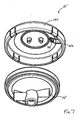
- Figures 5-7 illustrate an alternative arrangement of the catch mechanism 158.
- the recesses 160 are defined on an upper annular surface of the retainer 25' and the flexible tab 162 is correspondingly located on an upper surface of the cover 150.
- the recesses 160 are generally triangular in cross-section, as viewed in Figure 5, with the radially innermost wall portion being rounded ( Figure 6).
- the projection 164 is semi-cylindrical in shape. Otherwise, the embodiment of Figures 5-7 is similar in construction and function to the embodiment described immediately above.
Landscapes
- Physics & Mathematics (AREA)
- Fluid Mechanics (AREA)
- General Physics & Mathematics (AREA)
- Engineering & Computer Science (AREA)
- Automation & Control Theory (AREA)
- Control Of Fluid Pressure (AREA)
- Fuel-Injection Apparatus (AREA)
- Fluid-Pressure Circuits (AREA)
- Infusion, Injection, And Reservoir Apparatuses (AREA)
Claims (10)
- Dispositif de commande de régulateur de pression variable (10), comprenant :■ un corps de soupape comportant une arrivée de fluide (35), une sortie de fluide (40), une chambre de détection de pression de fluide (60) et un siège de soupape (50) en communication de fluide avec ladite arrivée et définissant une ouverture dans ladite chambre (60) ;■ un élément élastique (20) formant une paroi de ladite chambre (60) qui répond à une pression dans ladite chambre (60) ;■ une tige de soupape (75) reliée audit élément élastique (20) et s'étendant à travers ladite chambre (60) vers ledit siège de soupape (50) ;■ un élément de soupape (80)'supporté sur ladite tige de soupape (75) et coopérant avec ledit siège de soupape (50), ledit élément de soupape (80) étant situé entre le siège de soupape (50) et ladite arrivée de fluide (35) ;■ un dispositif de réglage (30) supporté par ledit corps de soupape et capable de se déplacer par rapport audit corps de soupape pour dévier ledit élément élastique (20) et éloigner l'élément de soupape (80) du siège de soupape (50) ; ledit corps de soupape comprend en outre un dispositif de retenue (25) monté en haut d'une base du corps de soupape pour retenir ledit élément élastique (20) contre ladite base, ledit dispositif de retenue comportant une ouverture destinée à recevoir ledit dispositif de réglage (30) ;■ un couvercle (150) configuré pour faire tourner ledit dispositif de réglage (30) avec celui-ci de sorte qu'une déviation dudit élément élastique (20) puisse être réglée par la rotation dudit dispositif de réglage (30) avec la rotation dudit couvercle (150),■ ledit dispositif étant caractérisé en ce que :■ ledit élément élastique (20) a une fonction d'auto-rétablissement ;■ ledit dispositif de réglage (30) comprend une surface configurée pour entrer en contact avec une partie dudit élément élastique (20) espacée vers l'intérieur d'une périphérie dudit élément élastique (20) et reliée à ladite tige de soupape (75), de sorte que seule ladite partie dudit élément élastique (20) fléchisse en réponse à des changements de pression dans ladite chambre (60) pour commander la position de l'élément de soupape (80) par rapport au siège de soupape (50), et dans lequel ledit couvercle (150) s'étend sur une partie supérieure dudit corps de soupape et auquel un utilisateur du dispositif peut accéder de l'extérieur de sorte que ledit couvercle (150) puisse être tourné à la main pour permettre le réglage d'une pression de sortie dudit dispositif sans utiliser d'outils.
- Dispositif selon la revendication 1, comprenant de plus un mécanisme d'encliquetage (158) définissant une pluralité de positions angulaires par rapport audit corps de soupape, ledit mécanisme d'encliquetage étant configuré pour positionner ledit couvercle dans une position de ladite pluralité de positions angulaires.
- Dispositif selon la revendication 2, dans lequel ledit mécanisme d'encliquetage (158) comprend une pluralité d'évidements (160) définis par un élément parmi ledit corps de soupape et ledit couvercle (150), et au moins une saillie (164) fixée par rapport à l'autre élément parmi ledit corps de soupape et ledit couvercle (150), ladite au moins une saillie étant configurée pour mettre en prise un évidement de ladite pluralité d'évidements (160).
- Dispositif selon la revendication 3, dans lequel ladite au moins une saillie (164) est poussée en engagement avec ledit évidement (160) de sorte que la rotation dudit couvercle (150) soit empêchée en l'absence d'un couple de rotation sur ledit couvercle (150) et la rotation du couvercle (150) est autorisée en réponse à un couple de rotation sur ledit couvercle (150).
- Dispositif selon la revendication 4, dans lequel lesdits évidements (160) sont définis par ledit corps de soupape et ladite au moins une saillie (164) est fixée pour tourner avec ledit couvercle (150), ledit couvercle (150) comprenant en plus au moins une partie de patte flexible (162), ladite au moins une saillie (164) étant définie par une surface de ladite partie de patte flexible (162).
- Dispositif selon la revendication 1, comprenant de plus un agencement indicateur (166) configuré pour lier une position angulaire dudit couvercle (150) par rapport audit corps de soupape à une pression de sortie de fluide prédéterminée.
- Dispositif selon la revendication 6, dans lequel ledit agencement indicateur (166) comprend une graduation de pression de sortie de fluide sur un élément parmi, ledit corps de soupape et ledit couvercle (150) et un indice de référence (170) sur l'autre élément parmi ledit corps de soupape et ledit couvercle (150), ledit indice de référence (170) pouvant être aligné sur une démarcation de ladite graduation de pression de sortie de fluide pour obtenir une pression de sortie de fluide souhaitée.
- Dispositif selon la revendication 7, dans lequel ladite graduation de pression de sortie de fluide comprend une graduation d'indice (168) et lesdites démarcations correspondent à une plage de pressions de sortie de fluide, ledit indice de référence (170) comprenant une fenêtre de visualisation (172) dimensionnée et formée de manière approximative pour afficher une simple démarcation de ladite graduation d'indice (168).
- Dispositif selon la revendication 1, dans lequel ledit couvercle comprend au moins une patte de blocage flexible (152), ladite patte de blocage flexible (152) définissant une surface de blocage (154), ledit corps de soupape comprenant une surface de retenue (156), ladite surface de blocage (154) étant configurée pour mettre en prise ladite surface de retenue (154) pour fixer sensiblement ledit couvercle dans une position axiale par rapport audit corps de soupape.
- Dispositif selon la revendication 9, dans lequel ladite surface de retenue (156) est une surface annulaire ininterrompue définie par ledit dispositif de retenue (25) dudit corps de soupape.
Applications Claiming Priority (3)
| Application Number | Priority Date | Filing Date | Title |
|---|---|---|---|
| US931385 | 1986-11-14 | ||
| US09/931,385 US6619308B2 (en) | 1999-07-09 | 2001-08-14 | Pressure regulator |
| PCT/US2002/027095 WO2003017020A1 (fr) | 2001-08-14 | 2002-08-14 | Regulateur de pression |
Publications (2)
| Publication Number | Publication Date |
|---|---|
| EP1419426A1 EP1419426A1 (fr) | 2004-05-19 |
| EP1419426B1 true EP1419426B1 (fr) | 2007-10-03 |
Family
ID=25460706
Family Applications (1)
| Application Number | Title | Priority Date | Filing Date |
|---|---|---|---|
| EP02766106A Expired - Lifetime EP1419426B1 (fr) | 2001-08-14 | 2002-08-14 | Regulateur de pression |
Country Status (12)
| Country | Link |
|---|---|
| US (6) | US6619308B2 (fr) |
| EP (1) | EP1419426B1 (fr) |
| JP (1) | JP2005500602A (fr) |
| KR (1) | KR100882239B1 (fr) |
| AT (1) | ATE374965T1 (fr) |
| AU (1) | AU2002329852B2 (fr) |
| CA (1) | CA2457776C (fr) |
| DE (1) | DE60222780T2 (fr) |
| IL (2) | IL160332A0 (fr) |
| MX (1) | MXPA04001354A (fr) |
| PL (1) | PL365949A1 (fr) |
| WO (1) | WO2003017020A1 (fr) |
Families Citing this family (49)
| Publication number | Priority date | Publication date | Assignee | Title |
|---|---|---|---|---|
| US6619308B2 (en) * | 1999-07-09 | 2003-09-16 | I-Flow Corporation | Pressure regulator |
| ITTO20050106U1 (it) * | 2005-07-25 | 2007-01-26 | Borla Ind | Camera di gocciolamento con regolatore di flusso integrato per linee medicali |
| US20070051409A1 (en) * | 2005-09-02 | 2007-03-08 | Belmont Instrument Corporation | Pressure responsive fluid flow control valves |
| ES1061777Y (es) * | 2005-12-02 | 2006-07-16 | Coprecitec Sl | Regulador de una presion de gas dual para un aparato electrodomestico. |
| WO2007104334A1 (fr) * | 2006-03-15 | 2007-09-20 | Norgren Gmbh | Soupape avec un diaphragme élastique |
| US8087428B1 (en) * | 2006-12-07 | 2012-01-03 | Beswick Engineering Co., Inc. | High pressure inlet regulator |
| US7967005B2 (en) * | 2007-04-13 | 2011-06-28 | Daniel Parrish | Dual fuel gas valve and gas grill |
| US20090214356A1 (en) * | 2008-02-22 | 2009-08-27 | Barrett Ii F Madison | Pump control valve |
| US8191574B1 (en) * | 2008-05-27 | 2012-06-05 | Davis Edward H | Visual indicator for air tank valve handle |
| US20110229877A1 (en) | 2008-07-07 | 2011-09-22 | Oxford Nanopore Technologies Limited | Enzyme-pore constructs |
| US8864106B2 (en) * | 2008-12-03 | 2014-10-21 | Emerson Process Management Regulator Technologies, Inc. | Valve seat apparatus having positive retention for use with fluid control devices |
| US8424561B1 (en) | 2009-02-25 | 2013-04-23 | Carroll G. Rowe | Pressure regulator |
| US9151450B2 (en) * | 2009-03-11 | 2015-10-06 | Victor Equipment Company | Compact robust gas pressure regulator |
| WO2011071501A1 (fr) * | 2009-12-11 | 2011-06-16 | Hewlett-Packard Development Company, L.P. | Appareil régulateur de pression afin de détecter un état d'épuisement de fluide |
| GB0921970D0 (en) * | 2009-12-16 | 2010-02-03 | Norgren Ltd C A | Pressure regulator |
| BR112012019952A2 (pt) | 2010-02-10 | 2016-04-26 | 3M Innovative Properties Co | válvula reguladora de pressão |
| US8522824B2 (en) * | 2010-04-23 | 2013-09-03 | Feldmeier Equipment, Inc. | Aseptic or sanitary diaphragm valve |
| JP5844359B2 (ja) * | 2010-06-29 | 2016-01-13 | リサーチ メディカル プロプライエタリー リミテッドResearch Medical Pty Ltd | 創傷ドレナージ制御装置 |
| WO2012042226A2 (fr) | 2010-10-01 | 2012-04-05 | Oxford Nanopore Technologies Limited | Appareil d'analyse biochimique et vanne rotative |
| HUP1000680A2 (hu) | 2010-12-21 | 2012-08-28 | Eurojet Medical Kft | Nyomásszabályozó szelep |
| US8960216B2 (en) * | 2011-03-21 | 2015-02-24 | Tescom Corporation | Diaphragm control valve having a universal diaphragm mounting location |
| DE102011018980A1 (de) * | 2011-04-28 | 2012-10-31 | Eagle Actuator Components Gmbh & Co. Kg | Ventil zur Begrenzung des Drucks im Kurbelwellengehäuse |
| GB2492955A (en) * | 2011-07-13 | 2013-01-23 | Oxford Nanopore Tech Ltd | One way valve |
| CN103946544B (zh) | 2011-09-15 | 2017-06-06 | 牛津纳米孔技术有限公司 | 泵 |
| US8905064B2 (en) | 2011-10-03 | 2014-12-09 | Seik Oh | Flow regulator for infusion pump and method of manufacturing the same |
| IN2014KN01195A (fr) | 2011-12-14 | 2015-10-16 | Numatics Inc | |
| JP5889648B2 (ja) | 2012-01-26 | 2016-03-22 | サーパス工業株式会社 | 流量調整装置 |
| JP5889649B2 (ja) * | 2012-01-26 | 2016-03-22 | サーパス工業株式会社 | 流量調整装置 |
| WO2014003578A1 (fr) | 2012-06-27 | 2014-01-03 | Fisher & Paykel Healthcare Limited | Appareil d'assistance respiratoire |
| US20140034155A1 (en) * | 2012-07-31 | 2014-02-06 | Fairchild Industrial Products Company | Valve Seat For A Pressure Regulator |
| DK177597B1 (en) * | 2012-09-17 | 2013-11-11 | Flowcon Internat Aps | Detachable grip for adjusting a valve and unit comprising a detachable grip and valve |
| KR101476042B1 (ko) | 2013-07-09 | 2014-12-23 | 김용무 | 약물주입용 레귤레이터 장치 및 이를 구비한 약물주입장치 |
| JP6282439B2 (ja) | 2013-10-30 | 2018-02-21 | 愛三工業株式会社 | 減圧弁 |
| US10151402B2 (en) | 2014-01-21 | 2018-12-11 | Asco, L.P. | Pressure controlled and pressure control valve for an inflatable object |
| US9551999B2 (en) * | 2015-05-15 | 2017-01-24 | Yung Shen Gas Appliance Co., Ltd. | Structure of gas regulator |
| CN108291487B (zh) | 2015-11-24 | 2021-08-17 | 沃尔布罗有限责任公司 | 节流触发器促动的节流部位置传感器和发动机控制模块 |
| DE112017000427T5 (de) | 2016-01-19 | 2018-10-04 | Walbro Llc | Durch den motoranwender initiiertes selbsteinstellungssystem |
| US10544745B2 (en) | 2016-01-20 | 2020-01-28 | Walbro Llc | Engine self-adjustment system |
| DE112017000486T5 (de) | 2016-01-25 | 2018-10-31 | Walbro Llc | Motor-notausschalter- und steueranordnung |
| DE112018001549T5 (de) | 2017-03-21 | 2019-12-05 | Walbro Llc | Zündmodul mit niedrigdrehzahl-steuerung |
| US20190388611A1 (en) | 2018-06-20 | 2019-12-26 | Baxter International Inc. | Infusion device |
| GB2585035B (en) * | 2019-06-25 | 2023-04-26 | Intersurgical Ag | An adjustable valve |
| TWI714279B (zh) | 2019-09-24 | 2020-12-21 | 丁原傑 | 溫度補償限流裝置與彈性輸液系統 |
| DE102020124541A1 (de) | 2020-09-21 | 2022-03-24 | Woco Industrietechnik Gmbh | Stellventilpositionserfassung |
| WO2022266924A1 (fr) * | 2021-06-24 | 2022-12-29 | 白翼志 | Structure d'identification et vanne à gaz utilisant une structure d'identification |
| CN217539625U (zh) | 2022-03-28 | 2022-10-04 | 上海荣威塑胶工业有限公司 | 用于充气产品的恒压阀和充气产品 |
| KR102499542B1 (ko) | 2022-08-29 | 2023-02-16 | 주식회사 넥젠 | 상시 폐쇄형 정밀 유체압력제어용 레귤레이터 |
| US12443208B2 (en) * | 2023-02-08 | 2025-10-14 | Rain Bird Corporation | Control zone devices, systems and methods |
| CN120404841B (zh) * | 2025-07-02 | 2025-10-10 | 常州威可特新材料有限公司 | 一种高弹力导热硅胶片热导检测装置 |
Family Cites Families (28)
| Publication number | Priority date | Publication date | Assignee | Title |
|---|---|---|---|---|
| US714143A (en) | 1902-04-08 | 1902-11-25 | Sven Carlson | Pressure-reducing valve. |
| GB479042A (en) | 1936-07-29 | 1938-01-31 | William Sugg & Company Ltd | Improvements in or relating to gas or other fluid pressure governors |
| US2960109A (en) * | 1957-01-07 | 1960-11-15 | Gen Controls Co | Flow regulator |
| US3547427A (en) | 1968-06-27 | 1970-12-15 | Robertshaw Controls Co | Reset mechanism for a spring assembly |
| US3552431A (en) | 1968-07-05 | 1971-01-05 | Singer General Precision | Fluidic pressure regulator |
| US3603217A (en) * | 1969-01-16 | 1971-09-07 | Robinson E S & A Canada | Method of forming a bag |
| US3603214A (en) | 1969-09-18 | 1971-09-07 | Robertshaw Controls Co | Pressure regulator converter |
| US3747629A (en) | 1972-06-28 | 1973-07-24 | Essex International Inc | Convertible fluid pressure regulator |
| US3825029A (en) | 1973-01-02 | 1974-07-23 | Robertshaw Controls Co | Plural range pressure regulator construction or the like and the method of making the same or the like |
| US3921664A (en) * | 1974-02-26 | 1975-11-25 | Edgar W Almquist | Vacuum powered ball valve fuel control |
| US4074694A (en) | 1976-04-09 | 1978-02-21 | Leemco, Inc. | Pressure regulator with soft valve seat |
| US4121615A (en) * | 1977-04-27 | 1978-10-24 | B. W. B. Controls, Inc. | Valve control with indicator |
| US4537387A (en) | 1982-09-30 | 1985-08-27 | Anatros Corporation | Precision valve assembly |
| US4622994A (en) * | 1984-08-15 | 1986-11-18 | Rosaen Nils O | Fluid handling device |
| US4621658A (en) | 1986-02-18 | 1986-11-11 | Honeywell Inc. | Non-removable spring holder for a pressure operated valve |
| US4744387A (en) | 1987-06-25 | 1988-05-17 | Otteman John H | Fluid pressure regulator |
| DE8709978U1 (de) * | 1987-07-21 | 1987-10-08 | A. u. K. Müller GmbH & Co KG, 4000 Düsseldorf | Elektromagnetventil, insbesondere Auslaufventil für Brühwasser |
| US5141022A (en) | 1990-04-12 | 1992-08-25 | Cashco, Inc | Pressure regulating valve apparatus |
| US5226446A (en) * | 1991-06-25 | 1993-07-13 | Eaton Corporation | Flow noise reduction |
| US5245997A (en) | 1991-12-05 | 1993-09-21 | Respirator Research, Inc. | Valve cartridge assembly for a pressure regulator of supplied air breathing apparatus |
| US5492146A (en) | 1992-09-02 | 1996-02-20 | Richards Industries, Inc. | Pressure regulators |
| US5732736A (en) | 1994-07-15 | 1998-03-31 | Veriflo Corporation | Pressure regulator with lower outlet pressure drop |
| US5609185A (en) * | 1995-05-31 | 1997-03-11 | H-Tech, Inc. | Valve indicator and handle assembly |
| US5697398A (en) * | 1995-08-08 | 1997-12-16 | Fisher Controls International, Inc. | Fluid pressure regulator with boost tube unit including stem guide and lever retainer |
| US5954090A (en) * | 1997-10-14 | 1999-09-21 | Amot Controls Corporation | Flexible flower indicator mechanism |
| US6619308B2 (en) * | 1999-07-09 | 2003-09-16 | I-Flow Corporation | Pressure regulator |
| US6273117B1 (en) * | 1999-07-09 | 2001-08-14 | I-Flow Corporation | Pressure regulator |
| US6254576B1 (en) | 1999-11-18 | 2001-07-03 | Medrip Ltd. | Pressure-responsive flow regulator and drug delivery devices employing the same |
-
2001
- 2001-08-14 US US09/931,385 patent/US6619308B2/en not_active Expired - Lifetime
-
2002
- 2002-08-14 AT AT02766106T patent/ATE374965T1/de not_active IP Right Cessation
- 2002-08-14 JP JP2003521462A patent/JP2005500602A/ja active Pending
- 2002-08-14 CA CA 2457776 patent/CA2457776C/fr not_active Expired - Lifetime
- 2002-08-14 EP EP02766106A patent/EP1419426B1/fr not_active Expired - Lifetime
- 2002-08-14 IL IL16033202A patent/IL160332A0/xx active IP Right Grant
- 2002-08-14 WO PCT/US2002/027095 patent/WO2003017020A1/fr not_active Ceased
- 2002-08-14 MX MXPA04001354A patent/MXPA04001354A/es active IP Right Grant
- 2002-08-14 PL PL02365949A patent/PL365949A1/xx not_active Application Discontinuation
- 2002-08-14 KR KR1020047002238A patent/KR100882239B1/ko not_active Expired - Fee Related
- 2002-08-14 DE DE2002622780 patent/DE60222780T2/de not_active Expired - Lifetime
- 2002-08-14 AU AU2002329852A patent/AU2002329852B2/en not_active Expired
-
2003
- 2003-09-16 US US10/663,363 patent/US6938642B2/en not_active Expired - Lifetime
-
2004
- 2004-02-11 IL IL160332A patent/IL160332A/en not_active IP Right Cessation
-
2005
- 2005-08-31 US US11/217,104 patent/US7114520B2/en not_active Expired - Lifetime
-
2006
- 2006-09-27 US US11/527,848 patent/US7264018B2/en not_active Expired - Lifetime
-
2007
- 2007-09-04 US US11/849,571 patent/US7546846B2/en not_active Expired - Fee Related
-
2009
- 2009-06-15 US US12/484,988 patent/US7766028B2/en not_active Expired - Lifetime
Also Published As
| Publication number | Publication date |
|---|---|
| US20090250124A1 (en) | 2009-10-08 |
| US20020104569A1 (en) | 2002-08-08 |
| PL365949A1 (en) | 2005-01-24 |
| US7766028B2 (en) | 2010-08-03 |
| US7546846B2 (en) | 2009-06-16 |
| US20060048822A1 (en) | 2006-03-09 |
| ATE374965T1 (de) | 2007-10-15 |
| US6619308B2 (en) | 2003-09-16 |
| DE60222780T2 (de) | 2008-07-17 |
| WO2003017020A1 (fr) | 2003-02-27 |
| US20040123906A1 (en) | 2004-07-01 |
| MXPA04001354A (es) | 2004-05-05 |
| EP1419426A1 (fr) | 2004-05-19 |
| US7264018B2 (en) | 2007-09-04 |
| US20070017580A1 (en) | 2007-01-25 |
| AU2002329852B2 (en) | 2008-08-21 |
| US6938642B2 (en) | 2005-09-06 |
| CA2457776A1 (fr) | 2003-02-27 |
| KR20040030108A (ko) | 2004-04-08 |
| KR100882239B1 (ko) | 2009-02-06 |
| US20070289644A1 (en) | 2007-12-20 |
| IL160332A0 (en) | 2004-07-25 |
| US7114520B2 (en) | 2006-10-03 |
| DE60222780D1 (de) | 2007-11-15 |
| CA2457776C (fr) | 2009-10-20 |
| HK1066286A1 (en) | 2005-03-18 |
| JP2005500602A (ja) | 2005-01-06 |
| IL160332A (en) | 2009-02-11 |
Similar Documents
| Publication | Publication Date | Title |
|---|---|---|
| EP1419426B1 (fr) | Regulateur de pression | |
| AU2002329852A1 (en) | Pressure regulator | |
| US6273117B1 (en) | Pressure regulator | |
| US5988204A (en) | Adjustable fluid flow regulator | |
| EP1793299B1 (fr) | Régulateur de pression de gaz double pour un appareil électroménager | |
| EP0452045B1 (fr) | Soupape à bec de canard, normalement fermée | |
| EP1903267A1 (fr) | Dispositif de soupape de régulation du débit et d' évacuation/d' arrêt de l' eau de type pilote | |
| US4669639A (en) | Dispensing and safety valve assembly for use in syphons and the like | |
| KR0175162B1 (ko) | 볼밸브 요소와 상부 밀봉가스킷을 갖춘 믹서밸브 | |
| US3062525A (en) | Adjusting device for pressure regulator valve | |
| US7261119B2 (en) | Pressure regulator with improved outlet pressure control | |
| CA1278492C (fr) | Soupape de surete | |
| EP0398858A2 (fr) | Régulateur de pression à action directe compensé droop et modifié pour pression élévée | |
| EP1173802B1 (fr) | Soupape regulatrice de pression a commande par selecteur | |
| HK1066286B (en) | Pressure regulator | |
| US5725073A (en) | Fluid metering device and compressed air lubricator including same | |
| EP0417882A2 (fr) | Perfectionnements aux régulateurs de pression de gaz | |
| GB2382639A (en) | An integrated pressure relief and flow control valve | |
| JPH0729390Y2 (ja) | ガス器具用圧力調整器 | |
| JP3601701B2 (ja) | 小型圧力調整器 | |
| CN211231751U (zh) | 一种用于柱塞泵的调压阀 | |
| JPH0381165B2 (fr) | ||
| JPS59144874A (ja) | 過流出防止弁 | |
| HUT77816A (hu) | Keverő csaptelep, valamint szelepbetét ilyen csaptelephez |
Legal Events
| Date | Code | Title | Description |
|---|---|---|---|
| PUAI | Public reference made under article 153(3) epc to a published international application that has entered the european phase |
Free format text: ORIGINAL CODE: 0009012 |
|
| 17P | Request for examination filed |
Effective date: 20040312 |
|
| AK | Designated contracting states |
Kind code of ref document: A1 Designated state(s): AT BE BG CH CY CZ DE DK EE ES FI FR GB GR IE IT LI LU MC NL PT SE SK TR |
|
| AX | Request for extension of the european patent |
Extension state: AL LT LV MK RO SI |
|
| RIN1 | Information on inventor provided before grant (corrected) |
Inventor name: PORTER, BILL Inventor name: FRY, STANLEY, E. Inventor name: MCPHEE, CHARLES, J. Inventor name: MASSENGALE, ROGER |
|
| 17Q | First examination report despatched |
Effective date: 20041104 |
|
| REG | Reference to a national code |
Ref country code: HK Ref legal event code: DE Ref document number: 1066286 Country of ref document: HK |
|
| GRAP | Despatch of communication of intention to grant a patent |
Free format text: ORIGINAL CODE: EPIDOSNIGR1 |
|
| GRAS | Grant fee paid |
Free format text: ORIGINAL CODE: EPIDOSNIGR3 |
|
| GRAA | (expected) grant |
Free format text: ORIGINAL CODE: 0009210 |
|
| AK | Designated contracting states |
Kind code of ref document: B1 Designated state(s): AT BE BG CH CY CZ DE DK EE ES FI FR GB GR IE IT LI LU MC NL PT SE SK TR |
|
| REG | Reference to a national code |
Ref country code: GB Ref legal event code: FG4D |
|
| RIN1 | Information on inventor provided before grant (corrected) |
Inventor name: PORTER, BILL Inventor name: MASSENGALE, ROGER Inventor name: FRY, STANLEY, E. C/O I-FLOW CORPORATION Inventor name: MCPHEE, CHARLES, J. |
|
| REG | Reference to a national code |
Ref country code: CH Ref legal event code: EP |
|
| REG | Reference to a national code |
Ref country code: IE Ref legal event code: FG4D |
|
| REF | Corresponds to: |
Ref document number: 60222780 Country of ref document: DE Date of ref document: 20071115 Kind code of ref document: P |
|
| REG | Reference to a national code |
Ref country code: HK Ref legal event code: GR Ref document number: 1066286 Country of ref document: HK |
|
| NLV1 | Nl: lapsed or annulled due to failure to fulfill the requirements of art. 29p and 29m of the patents act | ||
| REG | Reference to a national code |
Ref country code: CH Ref legal event code: PL |
|
| PG25 | Lapsed in a contracting state [announced via postgrant information from national office to epo] |
Ref country code: SE Free format text: LAPSE BECAUSE OF FAILURE TO SUBMIT A TRANSLATION OF THE DESCRIPTION OR TO PAY THE FEE WITHIN THE PRESCRIBED TIME-LIMIT Effective date: 20080103 Ref country code: CH Free format text: LAPSE BECAUSE OF FAILURE TO SUBMIT A TRANSLATION OF THE DESCRIPTION OR TO PAY THE FEE WITHIN THE PRESCRIBED TIME-LIMIT Effective date: 20071003 Ref country code: ES Free format text: LAPSE BECAUSE OF FAILURE TO SUBMIT A TRANSLATION OF THE DESCRIPTION OR TO PAY THE FEE WITHIN THE PRESCRIBED TIME-LIMIT Effective date: 20080114 Ref country code: NL Free format text: LAPSE BECAUSE OF FAILURE TO SUBMIT A TRANSLATION OF THE DESCRIPTION OR TO PAY THE FEE WITHIN THE PRESCRIBED TIME-LIMIT Effective date: 20071003 Ref country code: LI Free format text: LAPSE BECAUSE OF FAILURE TO SUBMIT A TRANSLATION OF THE DESCRIPTION OR TO PAY THE FEE WITHIN THE PRESCRIBED TIME-LIMIT Effective date: 20071003 |
|
| PG25 | Lapsed in a contracting state [announced via postgrant information from national office to epo] |
Ref country code: PT Free format text: LAPSE BECAUSE OF FAILURE TO SUBMIT A TRANSLATION OF THE DESCRIPTION OR TO PAY THE FEE WITHIN THE PRESCRIBED TIME-LIMIT Effective date: 20080303 Ref country code: BG Free format text: LAPSE BECAUSE OF FAILURE TO SUBMIT A TRANSLATION OF THE DESCRIPTION OR TO PAY THE FEE WITHIN THE PRESCRIBED TIME-LIMIT Effective date: 20080103 |
|
| PG25 | Lapsed in a contracting state [announced via postgrant information from national office to epo] |
Ref country code: AT Free format text: LAPSE BECAUSE OF FAILURE TO SUBMIT A TRANSLATION OF THE DESCRIPTION OR TO PAY THE FEE WITHIN THE PRESCRIBED TIME-LIMIT Effective date: 20071003 |
|
| EN | Fr: translation not filed | ||
| PG25 | Lapsed in a contracting state [announced via postgrant information from national office to epo] |
Ref country code: CZ Free format text: LAPSE BECAUSE OF FAILURE TO SUBMIT A TRANSLATION OF THE DESCRIPTION OR TO PAY THE FEE WITHIN THE PRESCRIBED TIME-LIMIT Effective date: 20071003 Ref country code: DK Free format text: LAPSE BECAUSE OF FAILURE TO SUBMIT A TRANSLATION OF THE DESCRIPTION OR TO PAY THE FEE WITHIN THE PRESCRIBED TIME-LIMIT Effective date: 20071003 |
|
| PLBE | No opposition filed within time limit |
Free format text: ORIGINAL CODE: 0009261 |
|
| STAA | Information on the status of an ep patent application or granted ep patent |
Free format text: STATUS: NO OPPOSITION FILED WITHIN TIME LIMIT |
|
| PG25 | Lapsed in a contracting state [announced via postgrant information from national office to epo] |
Ref country code: BE Free format text: LAPSE BECAUSE OF FAILURE TO SUBMIT A TRANSLATION OF THE DESCRIPTION OR TO PAY THE FEE WITHIN THE PRESCRIBED TIME-LIMIT Effective date: 20071003 Ref country code: SK Free format text: LAPSE BECAUSE OF FAILURE TO SUBMIT A TRANSLATION OF THE DESCRIPTION OR TO PAY THE FEE WITHIN THE PRESCRIBED TIME-LIMIT Effective date: 20071003 |
|
| 26N | No opposition filed |
Effective date: 20080704 |
|
| PG25 | Lapsed in a contracting state [announced via postgrant information from national office to epo] |
Ref country code: FR Free format text: LAPSE BECAUSE OF FAILURE TO SUBMIT A TRANSLATION OF THE DESCRIPTION OR TO PAY THE FEE WITHIN THE PRESCRIBED TIME-LIMIT Effective date: 20080718 |
|
| PG25 | Lapsed in a contracting state [announced via postgrant information from national office to epo] |
Ref country code: GR Free format text: LAPSE BECAUSE OF FAILURE TO SUBMIT A TRANSLATION OF THE DESCRIPTION OR TO PAY THE FEE WITHIN THE PRESCRIBED TIME-LIMIT Effective date: 20080104 |
|
| PG25 | Lapsed in a contracting state [announced via postgrant information from national office to epo] |
Ref country code: MC Free format text: LAPSE BECAUSE OF NON-PAYMENT OF DUE FEES Effective date: 20080831 |
|
| PG25 | Lapsed in a contracting state [announced via postgrant information from national office to epo] |
Ref country code: EE Free format text: LAPSE BECAUSE OF FAILURE TO SUBMIT A TRANSLATION OF THE DESCRIPTION OR TO PAY THE FEE WITHIN THE PRESCRIBED TIME-LIMIT Effective date: 20071003 |
|
| PG25 | Lapsed in a contracting state [announced via postgrant information from national office to epo] |
Ref country code: IE Free format text: LAPSE BECAUSE OF NON-PAYMENT OF DUE FEES Effective date: 20080814 Ref country code: CY Free format text: LAPSE BECAUSE OF FAILURE TO SUBMIT A TRANSLATION OF THE DESCRIPTION OR TO PAY THE FEE WITHIN THE PRESCRIBED TIME-LIMIT Effective date: 20071003 |
|
| PG25 | Lapsed in a contracting state [announced via postgrant information from national office to epo] |
Ref country code: FI Free format text: LAPSE BECAUSE OF FAILURE TO SUBMIT A TRANSLATION OF THE DESCRIPTION OR TO PAY THE FEE WITHIN THE PRESCRIBED TIME-LIMIT Effective date: 20071003 |
|
| PG25 | Lapsed in a contracting state [announced via postgrant information from national office to epo] |
Ref country code: LU Free format text: LAPSE BECAUSE OF NON-PAYMENT OF DUE FEES Effective date: 20080814 |
|
| PG25 | Lapsed in a contracting state [announced via postgrant information from national office to epo] |
Ref country code: TR Free format text: LAPSE BECAUSE OF FAILURE TO SUBMIT A TRANSLATION OF THE DESCRIPTION OR TO PAY THE FEE WITHIN THE PRESCRIBED TIME-LIMIT Effective date: 20071003 |
|
| PG25 | Lapsed in a contracting state [announced via postgrant information from national office to epo] |
Ref country code: IT Free format text: LAPSE BECAUSE OF NON-PAYMENT OF DUE FEES Effective date: 20080831 |
|
| REG | Reference to a national code |
Ref country code: GB Ref legal event code: 732E Free format text: REGISTERED BETWEEN 20120308 AND 20120314 |
|
| REG | Reference to a national code |
Ref country code: DE Ref legal event code: R081 Ref document number: 60222780 Country of ref document: DE Owner name: AVENT, INC. (N.D.GES.D. STAATES DELAWARE), ALP, US Free format text: FORMER OWNER: I-FLOW CORP., LAKE FOREST, CALIF., US Effective date: 20120315 Ref country code: DE Ref legal event code: R081 Ref document number: 60222780 Country of ref document: DE Owner name: KIMBERLY-CLARK WORLDWIDE, INC. (N.D.GES.D. STA, US Free format text: FORMER OWNER: I-FLOW CORP., LAKE FOREST, CALIF., US Effective date: 20120315 Ref country code: DE Ref legal event code: R082 Ref document number: 60222780 Country of ref document: DE Representative=s name: DEHNS, GB Effective date: 20120315 |
|
| REG | Reference to a national code |
Ref country code: GB Ref legal event code: 732E Free format text: REGISTERED BETWEEN 20150423 AND 20150430 |
|
| REG | Reference to a national code |
Ref country code: DE Ref legal event code: R082 Ref document number: 60222780 Country of ref document: DE Representative=s name: DEHNS, GB Ref country code: DE Ref legal event code: R081 Ref document number: 60222780 Country of ref document: DE Owner name: AVENT, INC. (N.D.GES.D. STAATES DELAWARE), ALP, US Free format text: FORMER OWNER: KIMBERLY-CLARK WORLDWIDE, INC. (N.D.GES.D. STAATES DELAWARE), NEENAH, WIS., US |
|
| PGFP | Annual fee paid to national office [announced via postgrant information from national office to epo] |
Ref country code: GB Payment date: 20190815 Year of fee payment: 18 |
|
| PGFP | Annual fee paid to national office [announced via postgrant information from national office to epo] |
Ref country code: DE Payment date: 20200804 Year of fee payment: 19 |
|
| REG | Reference to a national code |
Ref country code: DE Ref legal event code: R082 Ref document number: 60222780 Country of ref document: DE |
|
| GBPC | Gb: european patent ceased through non-payment of renewal fee |
Effective date: 20200814 |
|
| PG25 | Lapsed in a contracting state [announced via postgrant information from national office to epo] |
Ref country code: GB Free format text: LAPSE BECAUSE OF NON-PAYMENT OF DUE FEES Effective date: 20200814 |
|
| REG | Reference to a national code |
Ref country code: DE Ref legal event code: R119 Ref document number: 60222780 Country of ref document: DE |
|
| PG25 | Lapsed in a contracting state [announced via postgrant information from national office to epo] |
Ref country code: DE Free format text: LAPSE BECAUSE OF NON-PAYMENT OF DUE FEES Effective date: 20220301 |