EP1420124A1 - Keramikbauelement - Google Patents
Keramikbauelement Download PDFInfo
- Publication number
- EP1420124A1 EP1420124A1 EP03025578A EP03025578A EP1420124A1 EP 1420124 A1 EP1420124 A1 EP 1420124A1 EP 03025578 A EP03025578 A EP 03025578A EP 03025578 A EP03025578 A EP 03025578A EP 1420124 A1 EP1420124 A1 EP 1420124A1
- Authority
- EP
- European Patent Office
- Prior art keywords
- ceramic body
- ceramic
- prestressing
- component according
- ceramic component
- Prior art date
- Legal status (The legal status is an assumption and is not a legal conclusion. Google has not performed a legal analysis and makes no representation as to the accuracy of the status listed.)
- Granted
Links
- 239000000919 ceramic Substances 0.000 title claims abstract description 198
- 238000010276 construction Methods 0.000 claims abstract description 12
- 229910052751 metal Inorganic materials 0.000 claims abstract description 9
- 239000002184 metal Substances 0.000 claims abstract description 9
- 239000002131 composite material Substances 0.000 claims abstract description 5
- 239000004033 plastic Substances 0.000 claims abstract description 5
- 229920003023 plastic Polymers 0.000 claims abstract description 5
- 239000003365 glass fiber Substances 0.000 claims abstract 3
- 239000000835 fiber Substances 0.000 claims abstract 2
- 239000002657 fibrous material Substances 0.000 claims abstract 2
- 230000036316 preload Effects 0.000 claims description 48
- 230000000149 penetrating effect Effects 0.000 claims description 6
- 239000000463 material Substances 0.000 claims description 5
- 230000037072 sun protection Effects 0.000 claims description 4
- 238000009423 ventilation Methods 0.000 claims description 3
- 239000012209 synthetic fiber Substances 0.000 claims 1
- 229920002994 synthetic fiber Polymers 0.000 claims 1
- 210000002435 tendon Anatomy 0.000 description 12
- 238000005452 bending Methods 0.000 description 5
- 229910000831 Steel Inorganic materials 0.000 description 4
- 239000010959 steel Substances 0.000 description 4
- 238000003860 storage Methods 0.000 description 4
- 230000008878 coupling Effects 0.000 description 3
- 238000010168 coupling process Methods 0.000 description 3
- 238000005859 coupling reaction Methods 0.000 description 3
- 210000001061 forehead Anatomy 0.000 description 2
- 238000004519 manufacturing process Methods 0.000 description 2
- 238000012986 modification Methods 0.000 description 2
- 230000004048 modification Effects 0.000 description 2
- -1 However Substances 0.000 description 1
- 229910052782 aluminium Inorganic materials 0.000 description 1
- XAGFODPZIPBFFR-UHFFFAOYSA-N aluminium Chemical compound [Al] XAGFODPZIPBFFR-UHFFFAOYSA-N 0.000 description 1
- 230000002146 bilateral effect Effects 0.000 description 1
- 239000011449 brick Substances 0.000 description 1
- 229910010293 ceramic material Inorganic materials 0.000 description 1
- 230000000295 complement effect Effects 0.000 description 1
- 150000001875 compounds Chemical class 0.000 description 1
- 239000004567 concrete Substances 0.000 description 1
- 238000001035 drying Methods 0.000 description 1
- 239000011152 fibreglass Substances 0.000 description 1
- 238000010304 firing Methods 0.000 description 1
- 239000012634 fragment Substances 0.000 description 1
- 210000003128 head Anatomy 0.000 description 1
- 238000000034 method Methods 0.000 description 1
- 239000004570 mortar (masonry) Substances 0.000 description 1
- 125000006850 spacer group Chemical group 0.000 description 1
- 230000006641 stabilisation Effects 0.000 description 1
- 238000011105 stabilization Methods 0.000 description 1
- 238000005728 strengthening Methods 0.000 description 1
- 239000000725 suspension Substances 0.000 description 1
Images



Classifications
-
- E—FIXED CONSTRUCTIONS
- E04—BUILDING
- E04F—FINISHING WORK ON BUILDINGS, e.g. STAIRS, FLOORS
- E04F13/00—Coverings or linings, e.g. for walls or ceilings
- E04F13/07—Coverings or linings, e.g. for walls or ceilings composed of covering or lining elements; Sub-structures therefor; Fastening means therefor
- E04F13/08—Coverings or linings, e.g. for walls or ceilings composed of covering or lining elements; Sub-structures therefor; Fastening means therefor composed of a plurality of similar covering or lining elements
- E04F13/14—Coverings or linings, e.g. for walls or ceilings composed of covering or lining elements; Sub-structures therefor; Fastening means therefor composed of a plurality of similar covering or lining elements stone or stone-like materials, e.g. ceramics concrete; of glass or with an outer layer of stone or stone-like materials or glass
- E04F13/142—Coverings or linings, e.g. for walls or ceilings composed of covering or lining elements; Sub-structures therefor; Fastening means therefor composed of a plurality of similar covering or lining elements stone or stone-like materials, e.g. ceramics concrete; of glass or with an outer layer of stone or stone-like materials or glass with an outer layer of ceramics or clays
-
- E—FIXED CONSTRUCTIONS
- E04—BUILDING
- E04C—STRUCTURAL ELEMENTS; BUILDING MATERIALS
- E04C3/00—Structural elongated elements designed for load-supporting
- E04C3/02—Joists; Girders, trusses, or trusslike structures, e.g. prefabricated; Lintels; Transoms; Braces
- E04C3/20—Joists; Girders, trusses, or trusslike structures, e.g. prefabricated; Lintels; Transoms; Braces of concrete or other stone-like material, e.g. with reinforcements or tensioning members
- E04C3/22—Joists; Girders, trusses, or trusslike structures, e.g. prefabricated; Lintels; Transoms; Braces of concrete or other stone-like material, e.g. with reinforcements or tensioning members built-up by elements jointed in line
-
- E—FIXED CONSTRUCTIONS
- E04—BUILDING
- E04C—STRUCTURAL ELEMENTS; BUILDING MATERIALS
- E04C3/00—Structural elongated elements designed for load-supporting
- E04C3/02—Joists; Girders, trusses, or trusslike structures, e.g. prefabricated; Lintels; Transoms; Braces
- E04C3/20—Joists; Girders, trusses, or trusslike structures, e.g. prefabricated; Lintels; Transoms; Braces of concrete or other stone-like material, e.g. with reinforcements or tensioning members
- E04C3/26—Joists; Girders, trusses, or trusslike structures, e.g. prefabricated; Lintels; Transoms; Braces of concrete or other stone-like material, e.g. with reinforcements or tensioning members prestressed
-
- E—FIXED CONSTRUCTIONS
- E06—DOORS, WINDOWS, SHUTTERS, OR ROLLER BLINDS IN GENERAL; LADDERS
- E06B—FIXED OR MOVABLE CLOSURES FOR OPENINGS IN BUILDINGS, VEHICLES, FENCES OR LIKE ENCLOSURES IN GENERAL, e.g. DOORS, WINDOWS, BLINDS, GATES
- E06B9/00—Screening or protective devices for wall or similar openings, with or without operating or securing mechanisms; Closures of similar construction
- E06B9/01—Grilles fixed to walls, doors, or windows; Grilles moving with doors or windows; Walls formed as grilles, e.g. claustra
Definitions
- the invention relates to a ceramic component for arrangement in a building, preferably in a building or a stationary supporting structure.
- Ceramic components are not or only very limited to bending and Train resilient. They are in their arrangement in the building conventionally flat over their entire horizontal extent or over a large area of their horizontal extent, possibly over several evenly distributed bearing points supported. Ceramic components are used for.
- rod-shaped ceramic components are considered so-called baguettes used.
- baguettes In their assembled arrangement in the building at their foreheads or at a few points between their foreheads supported horizontally aligned in the fixed supporting structure. Due to the Low bending strength of the ceramic material can reduce the length dimensions of these baguettes can only be selected to a very limited extent. Already because of the The weight of the ceramic element can sometimes be lower Spans come to break the ceramic body. This also applies to Constructions in which the ceramic body is penetrated by a metal rod is, via which the component is supported in the stationary support structure. These constructions also come with the appropriate length dimensions of the ceramic body due to its own weight to break the Ceramic body.
- the invention has for its object a ceramic component of the beginning to create the type mentioned, which is capable of bending and / or Absorb tensile loads.
- Bend-resistant versions of the Ceramic component are made possible, which are elongated or plate-shaped and are preferably aligned horizontally in the building or any other fixed supporting structure can be hung.
- the ceramic component as a prestressed component is trained. It consists of a one-piece or multi-piece ceramic body, that of at least one one-part or multi-part prestressing tension member is penetrated. In the area of the opposite ends of the ceramic body are preload abutments supported with the ends of the penetrating Cooperate tension member so that the tension member on train and the ceramic body is prestressed under pressure.
- This biased component is then subject to bending and / or tension. It can be in a horizontal position more or less self-supporting in the building or another supporting structure to be assembled.
- the ceramic body can be elongated and / or plate-shaped Bodies are formed with a relatively large longitudinal or surface extension and supported at only a few support points spaced apart from one another to be assembled.
- the storage can take place in a rigid, stationary arrangement, so that the ceramic component in the structure or in another Support structure is rigidly immovable.
- the storage of the Ceramic component can, however, also take place in a movable bearing, so that the component in its arrangement in the building or in another Support structure movable, e.g. B. is pivotable.
- Versions with uniaxial preload are possible. advantageously, can make baguettes with a rod-shaped design in this way become.
- Tension members are provided. Designs are provided here which the tendons in a common plane parallel to each other are arranged. In this way, preferably plate-shaped components executed.
- Versions are provided in which the biasing tension member Passes through ceramic body in a through hole of the ceramic body, that is in which the tension member runs in the through hole.
- the Through hole is preferably as one in the ceramic manufacture of the Ceramic body formed through hole formed before firing. Versions in which the through hole is subsequently introduced or is subsequently edited in any way, are conceivable. There are Designs provided in which several such through holes in the Ceramic bodies are formed and in which several of the through holes can be penetrated by one or more tendons. at these versions, all through holes with the Tendons are equipped. However, they are also executions provided that some of the through holes remain free, that is, not from Tendons are penetrated.
- the biasing tension member can be arranged in the through hole so that it not in the area between the preload abutments with the ceramic body or is not at least radially in contact, that is, in these versions Preload tension member arranged at a distance from the wall of the through hole. It However, versions are also provided in which the prestressing tension member at least in a section in the area between the preload abutments in is in direct contact with the ceramic body or with little play to the Ceramic body is arranged, preferably in a recess in the wall of the through hole engages. This recess can be preferred Undercuts can be designed and in this way to a certain extent a hook between the tendon and the ceramic body in this Area.
- the prestressing tension member can preferably also be radial protruding legs or radially protruding arms which in the Engage recess.
- the biasing tension member in which between the Tension member and the ceramic body a positive or hooked Intervention takes place, the biasing tension member as an anti-rotation and / or Breakage protection of the ceramic body work.
- the tendon is in the receiving Through hole a backfill material added.
- the backfill material is preferably filled into the through hole after bracing. To this Wise further strengthening and stabilization of the prestressed Component received.
- the backfill material can be mortar or concrete or any other hardening compound.
- the ceramic body consists of two or more ceramic body modules is formed, which are preferably constructed identically, arranged in a row one behind the other form the ceramic body and one common one-part or multi-part composite tension member be penetrated.
- the adjacent ceramic body modules can immediately "crunch” can be arranged, but it can also be between the adjoining ceramic body modules an intermediate joint insert, for. B. a pressure-resistant plate made of plastic, metal or the like can be arranged.
- This intermediate joint insert can have a smooth surface or a textured one Have surface to realize a flat or a selective support.
- the intermediate joint insert is used at least to absorb the prestressing forces sufficiently pressure-resistant.
- the cross-section inlay preferably in cross section Cross section of the ceramic body module, correspondingly, in particular the same size as the cross section of the ceramic body module is formed.
- the intermediate joint insert is smaller in cross section or is larger than the cross section of the ceramic body module.
- the Intermediate joint insert can be with a preferred embodiment Fastening arm can be connected or as part of a fastening arm be designed to be connected to a fixed bearing for support in serves the building or another stationary supporting structure. This Fastening or support arm thus forms part of a Fastening device for supporting the ceramic component.
- the different versions of the ceramic component are advantageous each have a fastening device for connection to a fixed bearing the preload tension member and / or the preload abutment and / or the Ceramic body arranged or connectable.
- the fastener can, like already explained above, in the area of a joint between the ceramic body modules arranged or connectable. You can also additionally or alternatively in Area of the front end of the ceramic component and / or in the area of Preload abutment and / or in the area of one from the preload abutment projecting end of the biasing tension member arranged or connectable.
- the ceramic component can be immobile or movable on a stationary Bearings, e.g. B. on a stationary support structure or a building or movable component of the building.
- the ceramic component as immovable stored, stationary supported facade element is formed.
- the ceramic component can be designed as a movably mounted exposure or Ventilation wing be formed.
- the ceramic component as a fixed, preferably horizontal or vertically aligned sun protection wing or as a movably mounted wing Sun protection and / or climate protection device is formed.
- the different versions result from the preload of the Ceramic component offers a wide range of design options in terms of dimensions and design as well as the design of the suspension of the Components in the building or any other, preferably stationary Supporting structure.
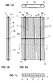
- FIGS. 1 a to 1 d are a prestressed plate-shaped component. It has a plate-shaped Ceramic body 1, which is penetrated by two tendons 2.
- the Preload tension members 2 are in on opposite ends of the Ceramic body 1 supported preload abutments 3 in the region of their front ends clamped and thus acted on train. The ceramic body 1 is thereby open Pressure applied.
- the biasing tension members 2 are designed as straight tension rods in the illustrated embodiment as metal rods. They take hold of the plate-shaped ceramic body 1 in the longitudinal direction. They are parallel to each other arranged at a mutual distance and run at a distance and parallel to the opposite longitudinal edges of the ceramic body 1.
- Each Tension member 2, i.e. each tension rod is in a longitudinal one Through hole 4 arranged.
- the tension rod runs in the axial direction Longitudinal central axis of the through hole 4 with a radial distance from the Hole wall. In the illustrated embodiment, between the Through holes 4, in which the tension rods 2 run, six more parallel through holes 4 are arranged, in which no tendons 2 are arranged.
- All Through holes 4 are in the embodiment in a common plane arranged the longitudinal median plane between the front and the back of the plate-shaped ceramic body 1 forms.
- the preload abutments 3 are in the illustrated embodiment in Fig. 1 a to c designed as a screw connection.
- the ends of the tension rods 2 are provided with an external thread onto which the preload abutment 3 is screwed.
- the preload abutment 3 has an internal thread member.
- Internal thread member of the preload abutment 3 is designed as a screw nut 3a, which with the interposition of a thrust washer 3b on the external thread of the Tension member is screwed on.
- the thrust washer 3b rests on one the end face of the ceramic body 1 overlying pressure-resistant end plate 1 a.
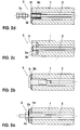
- FIG. 2a to 2d are various modified versions of Prestressing abutments 3 shown.
- the preload abutment in Fig. 2a corresponds to in its construction the abutments, as described in the above Embodiment are shown in Figs. 1 a and 1 b.
- Fig. 2c shows a recessed arrangement of the preload abutment 3, this Preload abutment is composed of appropriate components like that Preload abutment in Fig. 2a.
- Fig. 2c is only a countersunk hole 1l in the area of End of the through hole 4 is formed.
- this countersunk hole 1l Preload abutment arranged, the structure of the pretension abutment in Fig. 2a corresponds.
- the externally threaded end of the tension member 2 ends in the countersunk hole 1l, the thrust washer 3b is at the bottom of the countersunk hole 1l supported. The threaded end of the tension rod 2 passes through the thrust washer 3b.
- the clamping nut 3a is screwed onto the thread end and provides under Support on the thrust washer 3b the preload.
- an Allen screw 3i is used as a preload screw member provided with internal thread. This Allen screw engages in the through hole and is supported with her head on the end face of the ceramic body 1 Interposition of the thrust washer 3b.
- a coupling sleeve 3h with bilateral Internal thread provided, which sunk in the front end of the through hole 2 is arranged, with one end with the internal thread on one Side is screwed to the threaded end of the tension rod 2 and with the Internal thread on its other side receives a clamping screw 3s, one Has lock nut 3k.
- the clamping screw 3s is in the corresponding Internal thread of the coupling sleeve screwed in 3h.
- The is supported Lock nut 3k on the edge of a hat-shaped thrust washer 3t on the End face of the ceramic body 1 supported in the through hole 2 with inclusion the coupling sleeve engages 3h.
- Such preload abutment 3 can each on both ends Preload tension members 2 may be arranged. With modified versions can however, such an adjustable preload abutment 3 only at one end be provided, while at the other end of the tendons a not adjustable abutment can be arranged, the z. B. only as a disc can be formed, which is fixedly connected to the tendon and itself the end face of the ceramic body 1 is supported.
- the ceramic body 1 is the one shown in FIGS. 1a to 1d Embodiments of two arranged one behind the other Ceramic body modules assembled 1m.
- the ceramic body modules are 1m trained identically. They border with their mutually facing end faces to each other with the interposition of a pressure-resistant joint intermediate layer 1f.
- the Joint intermediate layer 1f has identical perforations as the ceramic body modules 1m on.
- the prestressing tension rods 2 each pass through both in succession arranged ceramic body modules 1m and clamp them against each other when the preload abutments 3 are tightened.
- modified versions can also the ceramic body modules 1m and / or the joint spacers 1f be different.
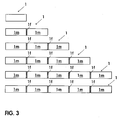
- Embodiments of the ceramic body 1 also from more than two Ceramic body modules 1m can be composed, but it can also consist of only one be formed single ceramic body module 1m.
- Such different variants are shown in Fig. 3.
- the ceramic body modules are braced 1m each in the same way as that described above Embodiment of Fig. 1 on tension members 2, each of the entire Pass through ceramic body 1 and arranged on the end face, not shown Preload abutment 3 can be preloaded.
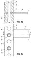
- the bracket 5 is integral with the Joint liner 1f connected.
- the support arm 5 protrudes at right angles from the back of the plate-shaped Ceramic body 1 from.
- the bearing arm can also projecting with an angle deviating from 90 °.
- the Support arm 5 is also arranged there in the intermediate joint area. However, it is not integrally connected to the intermediate layer 1f, but as a separate arm 5 formed, which is provided with a hook-shaped receptacle 5a at its end and into a receiving groove of a disc-shaped intermediate joint bearing 1s engages below and via a clamping screw connection 5k on the disc-shaped intermediate joint bearing 1f is fixed.
- the Clamping screw connection 5k consists of a clamping screw 5s, which in one is screwed to the support arm 5 firmly connected threaded sleeve 5h and with its clamping screw end with tightened clamping screw 5s in the Receiving groove of the intermediate joint bearing 1s engages by clamping.
- a clamping screw 5s As from the Sectional view Fig. 5b is disc-shaped Intermediate joint bearing 1s from an inner disc with a small diameter and put together two axially outer disks with a larger diameter.
- This Disk device 1s is in the joint area between the Ceramic body modules arranged 1m and is clamped by the Ceramic body modules 1m tightly held.
- the disk device 1s has a central through hole on that of the tension rod 2 coaxially with play is penetrated.
- the intermediate joint storage 1s can be modified Designs also without receiving groove, preferably as a cylindrical one Bearing body, be formed.
- Correspondingly constructed support arms 5 can also in the area of the front ends Ceramic body 1 may be arranged or for attachment e.g. to the over the Preload abutment 3 protruding ends of the preload tension rods 2 attack and be non-rotatably fixed there. Alternatively or additionally, the Support arms 5, however, also directly on components of the preload abutment 3 be attached or connected to them.
- each Facade panel 10 in Fig. 6 consists of five braced together in In the longitudinal direction one behind the other arranged plate-shaped modules 10m are constructed identically.
- Each of the composite Facade panels 10 are penetrated by two tendons 2, respectively are biased via abutments 3 supported at the end, so that the Form facade panels of prestressed components.
- two support arms 5 are provided for fixed attachment of the Prestressed facade panels 10 for fixed attachment of the Prestressed facade panels 10.
- the support arms 5 are attached to a stationary on-site substructure 12 which is in front of the Outside wall 11 of a building is arranged.
- the modules can also be 10m in average and / or length design be different, preferably similar. You can e.g. also be profiled differently from the rectangular or round cross-sectional design.
- Prestressed ceramic facade panels 20 in a fixed, building-side Support structure 22 used.
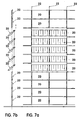
- This building-side support structure 22 exists from stationary mounted vertical beams 22 on which the prestressed plate-shaped components 20 pivotable about a horizontal axis of rotation 20h are stored.
- corresponding pivot bearings on the vertical supports arranged in which the prestressed elements are rotatably suspended.
- the in the pivot pin engaging through the front end protruding ends of the tension rods 2 are formed.
- you can but also corresponding separate bearing rods can be provided, which in the prestressed ceramic components, preferably passing through the ceramic body 1, can be arranged without bias.
- the swivel-mounted Facade panels 20 form adjustable in the embodiment in FIG. 7 Exposure and ventilation wing.
- prestressed ceramic components 30 which have a structure corresponding to the elements in the exemplary embodiments described above, are used in a staircase construction. They are supported in the area of their front ends in lateral steel cheeks 32 by the front ends of the prestressing tension rods 2 reaching through the prestressing abutment 3 engaging in bearings in the lateral steel cheeks 32.
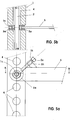
- the construction shown forms a bridge, each with two steps 34 on both opposite sides and a connecting platform 35, which connects the two upper steps 34.
- the steps 34 on the two sides are each formed by three step-wise arranged prestressed plate-shaped components 30, the bridge platform is formed by the components forming the top two steps and a further component 30 arranged between them.
- a railing 36 which consists of three vertical steel girders 36v, on which a prestressed plate-shaped ceramic component 39 consisting of two plate-shaped modules 39m is arranged vertically.
- This prestressed component 39 is held over the vertical railing posts 36v, in that the two outer posts 36v on the end faces of the component 39 are coupled to the ends of the prestressing tension rods protruding from the prestressing bearings 3 and the middle post 36v is connected to the joint intermediate layer which is in the area the joint is arranged between the plate-shaped modules 39m of the ceramic component.
- a handrail 36h is arranged, which can be formed from a metal rod or the like.
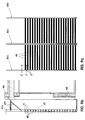
- rod-shaped prestressed ceramic components 40 are arranged in a building in that the baguettes 40 are each supported horizontally and parallel with a vertical distance from one another in a common vertical plane with a horizontal distance parallel to a building wall 48 in a front of the building wall 48 hanging support structure 47 are arranged.
- the baguettes 40 are in this case mounted in the support structure 47 via support arms 5 which engage the baguettes 40 on the end face.
- the support structure 47 consists of vertical profiles 47v, which is suspended in front of the building wall 48 via support struts 47t.
- the vertical profiles 47v form an assembly plane which is arranged vertically aligned at a distance from the vertical building wall 48.
- the baguettes 40 correspond in their basic structure to the previous ones described prestressed plate-shaped ceramic bodies.
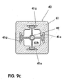
- This body is as shown in Fig. 9c as Hollow profile body formed with a central profile cavity 41h.
- the cross section the profile body is square.
- the profile cavity also has a square shape Basic shape, but in each case in the opposite sides of the square centrally, undercut recesses 41a are arranged, which in the embodiment shown in cross section are dovetail-shaped.
- These undercut recesses 41a are grooves that extend in the longitudinal direction of the profile in the opposite walls of the profile cavity.
- a biasing element 42 is arranged, which in the illustrated embodiment as a profile with a cross-shaped profile cross section is trained.
- the profile legs arranged at right angles to each other are on their free end each in cross-section T-shaped. These are T-shaped in cross-section Ends engage in the undercut grooves 41a.
- the bias tension member 42 is supported with its ends in the end faces of the ceramic body 41 Prestressed abutments, not shown. You can send them to the End faces of the ceramic body on pressure-resistant end plates arranged there be supported. By tightening the preload abutment, the preload tension member becomes 42 biased to train, whereby the ceramic body 41 is biased under pressure. It thereby becomes the baguette 40 as a prestressed ceramic component educated.
- Baguettes are aligned due to the preload in terms of their Bending tensile values increased so that they do not compared to conventional ones the aforementioned baguettes can withstand larger wind loads and larger ones Spans can be stored.
- the engagement of the radially projecting profile leg Preload tension elements 42 prevent the ceramic body 41 from rotating in the Get mounting position.
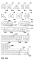
- FIG. 10a shows ceramic bodies 101 which are used to form a baguette-like prestressed ceramic component can be used.
- she each have a profile cavity 101 h, which extends in the longitudinal direction of the Profile body extends axially and in which one or more, not shown Tension members can be arranged.
- the outside cross section of the Ceramic body 101 is different in the different versions, that means circular, square, triangular, oval, hexagonal, star-shaped, etc.
- the cross section of the profile cavity 101h is also in the exemplary embodiments different, namely circular, square and triangular.
- Profile cavities 102k with a smaller cross section present. These profile cavities are not intended to accommodate pre-tensioning elements, but only for manufacturing reasons in connection with the drying and the Burning process present in the ceramic body.
- the other embodiments shown in FIG. 10a are Ceramic body 103 and 104. They each have a plurality of parallel profile cavities 103h or 104h, which in several mutually parallel planes or in planes arranged at an angle to one another are arranged. Even in these Profile cavities 103h and 104h can be introduced with tension members become. In addition, there are also others in the ceramic bodies 103, 104 Profile cavities 103k or 104k with a smaller cross-section are present, which are not used for Inclusion of tension members are provided.
- the ceramic bodies 105, 106, 107 and 108 are hollow profile bodies with square, round, triangular or oval outer cross section with a central profile cavity 105h, 106h, 107h, 108h each with a large Cross sectional area. Further profile cavities with a smaller cross-sectional area are shown in the profile body arranged coaxially around the central profile cavity. to The components can be preloaded in the central Profile cavity can be arranged. Additionally or alternatively, however the outer profile cavities with a smaller cross section preload elements be used.
- the further variants shown in FIG. 10b are ceramic Profile body 109, 110, 111, 112, which are wing-shaped or teardrop-shaped in cross section are formed and also several profile cavities for receiving Have pre-tensioning elements.
- the profile cavities recesses in particular undercut longitudinal grooves are formed, in which the biasing tension elements or with Preload elements connected radial legs or radial arms or separate non-prestressed anchor elements engage to prevent rotation and / or to form fall protection.
- the Preload elements or separate anchor elements can also be obtained in that the Preload elements or separate anchor elements that pass through the ceramic body reach through the cavity, designed accordingly complementary become.
- the pre-tensioning elements and / or the anchor elements can preferably made of metal, e.g. Aluminum or steel, others Materials e.g. However, plastics, fiberglass and composites can are also used.
- the pretensioning element preferably as a separate component that passes through the anchor element.
- the anchor element a e.g. has tubular body, which the pre-tensioning element e.g. reaches through as a tension rod.
Landscapes
- Engineering & Computer Science (AREA)
- Architecture (AREA)
- Structural Engineering (AREA)
- Civil Engineering (AREA)
- Chemical & Material Sciences (AREA)
- Ceramic Engineering (AREA)
- Dispersion Chemistry (AREA)
- Bridges Or Land Bridges (AREA)
- Building Environments (AREA)
Abstract
Description
- Fig. 1a
- eine geschnittene Frontansicht eines plattenförmigen vorgespannten Keramikbauelements, bestehend aus zwei Keramikkörpermodulen;
- Fig. 1b
- eine Horizontalschnittansicht entlang Linie B-B in Fig. 1a;
- Fig. 1c
- eine Vertikalschnittansicht entlang Linie C-C in Fig. 1a;
- Fig. 1d
- eine Seitenansicht in Fig. 1a;
- Fig. 2a bis Fig. 2d
- eine Horizontalschnittansicht im Bereich des Vorspannwiderlagers in Fig. 1 a für vier abgewandelte Ausführungsbeispiele;
- Fig. 3
- eine Frontansicht von sechs vorgespannten Keramikbauelementen, die sich darin unterscheiden, daß sie aus einem oder unterschiedlich vielen Keramikkörpermodulen zusammengesetzt sind;
- Fig. 4a
- eine Seitenansicht im Bereich der Zwischenfuge mit an der Zwischenfugeneinlage einstückig angeformtem Befestigungsarm;
- Fig. 4b
- eine Schnittansicht entlang Linie B-B in Fig. 4a;
- Fig. 5a und Fig. 5b
- den Fig. 4a und 4b entsprechende Darstellungen eines abgewandelten Ausführungsbeispiels mit in die Zwischenfugeneinlage hakenförmig untergreifendem Befestigungsarm;
- Fig. 6a
- Frontansicht einer vor einer Gebäudewand aufgehängten hinterlüfteten Fassadenwandkonstruktion mit vorgespannten Fassadenplatten;
- Fig. 6b
- Draufsicht in Fig. 6a von oben;
- Fig. 6c
- Seitenansicht in Fig. 6a, teilweise geschnitten;
- Fig. 7a
- Frontansicht einer vor einer Gebäudewand in einer ortsfesten Tragkonstruktion aufgehängten Fassadenwand mit um ihre mittlere Horizontalachse schwenkbar gelagerten Flügeln aus vorgespannten plattenförmigen Keramikbauelementen;
- Fig. 7b
- Seitenansicht in Fig. 7a;
- Fig. 8a
- Frontansicht einer Brückenkonstruktion, mit beidseitig jeweils drei Stufen und einem Brückenpodest, bestehend aus horizontal angeordneten vorgespannten plattenförmigen Keramikbauelementen, und einem Geländer, bestehend aus einem vertikal angeordneten plattenförmigen Keramikbauelement;
- Fig. 8b
- Seitenansicht in Fig. 8a von links;
- Fig. 8c
- Draufsicht in Fig. 8a von oben;
- Fig. 9a
- Frontansicht einer vor einer Gebäudewand in einer am Gebäude befestigten Tragkonstruktion angeordneten Verbindung aus Baguettes;
- Fig. 9b
- Seitenansicht in Fig. 9a;
- Fig. 9c
- Schnittansicht eines Baguettes entlang Linie C-C in Fig. 9a;
- Fig. 10a
- Querschnittsansicht von Keramikkörpern mit unterschiedlich ausgebildeten Querschnitten und unterschiedlicher Anordnung und Ausgestaltung von Durchgangslöchern;
- Fig. 10b
- eine Fig. 10a entsprechende Darstellung weiterer Ausführungen von Keramikkörpern;
In Fig. 9 sind stabförmige vorgespannte keramische Bauelemente 40, sogenannte Baguettes, in einem Bauwerk angeordnet, indem die Baguettes 40 jeweils horizontal und parallel mit vertikalem Abstand zueinander in einer gemeinsamen vertikalen Ebene mit horizontalem Abstand parallel zu einer Gebäudewand 48 abgestützt in einer vor der Gebäudewand 48 hängenden Tragkonstruktion 47,angeordnet sind. Die Baguettes 40 sind hierbei über stirnseitig an den Baguettes 40 angreifende Tragarme 5 in der Tragkonstruktion 47 montiert. Die Tragkonstruktion 47 besteht aus vertikalen Profilen 47v, die vor der Gebäudewand 48 über Tragstreben 47t aufgehängt ist. Die vertikalen Profile 47v bilden eine Montageebene, die vertikal ausgerichtet mit Abstand vor der vertikalen Gebäudewand 48 angeordnet ist.
Claims (29)
- Keramikbauelement zur Anordnung in einem Bauwerk, vorzugsweise in einem Gebäude oder einer ortsfesten Tragkonstruktion,
mit einem einteiligen oder mehrteiligen Keramikkörper (1, 10, 20, 30, 39, 40, 101, 103, 104, 105, 106, 107, 108, 109, 110, 111) und mindestens einem den Keramikkörper durchgreifenden und/oder entlanggreifenden Vorspannzugglied (2) mit an gegenüberliegenden Enden des Vorspannzugglieds (2) angeordneten Vorspannwiderlagern (3), die sich im Bereich von gegenüberliegenden Enden des Keramikkörpers unter Vorspannung des Keramikkörpers abstützen. - Keramikbauelement nach Anspruch 1,
dadurch gekennzeichnet, daß nur ein den Keramikkörper durchgreifendes Vorspannzugglied (2) vorgesehen ist oder daß mehrere den Keramikkörper durchgreifende Vorspannzugglieder (2) vorgesehen sind. - Keramikbauelement nach Anspruch 2,
dadurch gekennzeichnet, daß mehrere in einer gemeinsamen Ebene parallel zueinander angeordnete Vorspannzugglieder (2) vorgesehen sind, die den Keramikkörper durchgreifen. - Keramikbauelement nach Anspruch 2,
dadurch gekennzeichnet, daß mehrere nicht in einer gemeinsamen Ebene angeordnete Vorspannzugglieder (2) vorgesehen sind, die den Keramikkörper durchgreifen. - Keramikbauelement nach einem der vorangehenden Ansprüche,
dadurch gekennzeichnet, daß der Keramikkörper mindestens ein Durchgangsloch (4) aufweist, das von dem mindestens einen Vorspannzugglied (2) oder mehreren der Vorspannzugglieder (2) durchgriffen wird. - Keramikbauelement nach Anspruch 5,
dadurch gekennzeichnet, daß der Keramikkörper mehrere Durchgangslöcher (4) aufweist, wobei mehrere der Durchgangslöcher (4) jeweils von einem oder mehreren Vorspannzuggliedern (2) durchgriffen werden. - Keramikbauelement nach einem der vorangehenden Ansprüche,
dadurch gekennzeichnet, daß der Keramikkörper mehrere Durchgangslöcher (4) aufweist, von denen mindestens eines von keinem der Vorspannzugglieder (2) durchgriffen wird. - Keramikbauelement nach einem der vorangehenden Ansprüche,
dadurch gekennzeichnet, daß das Vorspannzugglied (2) mit einem Abschnitt, der zwischen seinem mit den Vorspannwiderlagern (3) versehenen Enden angeordnet ist, mit dem Keramikkörper zusammenwirkt, vorzugsweise in unmittelbarem Kontakt mit dem Keramikkörper steht und/oder in eine vorzugsweise hinterschnittene Ausnehmung des Durchgangslochs (4) eingreift oder
daß das Vorspannzugglied (2) im Bereich zwischen seinen Vorspannwiderlagern (3) mit dem Keramikkörper nicht in Kontakt stehend angeordnet ist, sondern vorzugsweise mit Abstand zur Wandung des Durchgangsloch (4) angeordnet ist. - Keramikbauelement nach einem der Ansprüche 5 bis 8,
dadurch gekennzeichnet, daß in dem das Vorspannzugglied (2) aufnehmenden Durchgangsloch (4) ein Verfüllmaterial aufgenommen ist. - Keramikbauelement nach einem der vorangehenden Ansprüche,
dadurch gekennzeichnet, daß das Vorspannzugglied (2) als weitgehend starres Element mit vorzugsweise vollem Querschnitt, z.B. als Stab, insbesondere Rundstab z. B. aus Metall ausgebildet ist oder als weitgehend elastisches Element mit vorzugsweise mit vorzugsweise vollem Querschnitt, z.B. als Stab, insbesondere Kunststoffstab oder aus Glasfaser, Fasermaterial, Glasfaser, Faserverbundwerkstoff ausgebildet ist. - Keramikbauelement nach einem der vorangehenden Ansprüche,
dadurch gekennzeichnet, daß das Vorspannzugglied (2) aus Litzen ausgebildet ist, vorzugsweise aus Litzen aus gebündelten Metallstäben oder aus Litzen aus Draht, z.B. Drahtseilen oder aus Litzen aus Kunstfasern. - Keramikbauelement nach einem der vorangehenden Ansprüche,
dadurch gekennzeichnet, daß der Keramikkörper aus zwei oder mehr Keramikkörpermodulen (1 m, 10m, 39m) ausgebildet ist, die vorzugsweise identisch aufgebaut, in einer Reihe hintereinander angeordnet den Keramikkörper bilden und von einem gemeinsamen einteiligen oder mehrteilig zusammengesetzten Vorspannzugglied (2) durchgriffen werden. - Keramikbauelement nach Anspruch 12,
dadurch gekennzeichnet, daß das mehrteilig zusammengesetzte Vorspannzugglied (2) aus mindestens zwei Vorspannzuggliederabschnitten besteht, die jeweils nur ein oder mehrere der Keramikkörpermodule durchgreifen und vorzugsweise im Bereich einer Fuge zwischen zwei Keramikkörpermodule über ein Verbindungselement, vorzugsweise eine Verbindungsmuffe gekuppelt sind. - Keramikbauelement nach Anspruch 12 oder 13,
dadurch gekennzeichnet, daß aneinander grenzende Keramikkörpermodule (1m, 10m) unter unmittelbarer gegenseitiger flächiger vorzugsweise vollflächiger oder mehr oder weniger punktueller vorzugsweise teilflächiger oder geringflächiger Anlage oder unter Zwischenschaltung einer Zwischenfugeneinlage (1f, 1s), z.B. einer druckfesten Platte, insbesondere aus Kunststoff, Metall oder dergleichen angeordnet sind, wobei vorzugsweise vorgesehen ist, daß die Zwischenfugeneinlage eine glatte Oberfläche oder strukturierte Oberfläche aufweist. - Keramikbauelement nach Anspruch 14,
dadurch gekennzeichnet, daß die Zwischenfugeneinlage (1f, 1s) im Querschnitt dem Querschnitt des Keramikkörpermoduls entspricht, vorzugsweise gleich groß wie der Querschnitt des Keramikkörpermoduls ausgebildet ist und/oder größer oder kleiner als der Querschnitt des Keramikkörpermoduls ausgebildet ist. - Keramikbauelement nach Anspruch 14 oder 15,
dadurch gekennzeichnet, daß die Zwischenfugeneinlage (1f, 1s) mindestens zur Aufnahme der Vorspannkraft druckfest ausgebildet ist. - Keramikbauelement nach einem der Ansprüche 14 bis 16,
dadurch gekennzeichnet, daß die Zwischenfugeneinlage (1f, 1s) eine Lochung aufweist, die mindestens im Bereich des durchgreifenden Vorspannzugglieds (2) ein Loch aufweist und/oder gleich oder abweichend von der Lochung des Keramikkörpermoduls ausgebildet ist. - Keramikbauelement nach einem der vorangehenden Ansprüche,
dadurch gekennzeichnet, daß das Vorspannwiderlager (3) an der Stirnseite des Keramikkörpers übergreifend aufliegend oder vollständig oder teilweise versenkt im Keramikkörper angeordnet ist. - Keramikbauelement nach Anspruch 18,
dadurch gekennzeichnet, daß das Vorspannwiderlager (3) als Schraubverbindung und/oder Klemmvorrichtung, z.B. Klemmbackenkonstruktion ausgebildet ist. - Keramikbauelement nach Anspruch 18 oder 19,
dadurch gekennzeichnet, daß das Vorspannwiderlager (3) eine Druckplatte, vorzugsweise Druckscheibe aufweist, die sich außenliegend auf der Stirnseite des Keramikkörpers oder innenliegend in einer Versenkung der Stirnseite des Keramikkörpers abstützt und von einem außenliegenden Schraubelement, z.B. Mutter oder Schraubenkopf oder einem Bauelement der Klemmvorrichtung beaufschlagt wird. - Keramikbauelement nach einem der Ansprüche 18 bis 20,
dadurch gekennzeichnet, daß das Vorspannwiderlager (3) eine Verbindungsmuffe aufweist, die mit ihrem einen Ende mit dem Ende des Vorspannzugglieds und mit ihrem anderen Ende mit einer Schraube oder einer Mutter des Vorspannwiderlagers verschraubt ist, wobei vorzugsweise vorgesehen ist, daß die Verbindungsmuffe in einem hutförmigen Drucklager angeordnet ist, das sich an der Stirnseite des Keramikkörpers abstützt. - Keramikbauelement nach einem der vorangehenden Ansprüche,
dadurch gekennzeichnet, daß das Vorspannwiderlager (3) sich auf einem an der Stirnseite des Keramikkörpers angeordneten vorzugsweise plattenförmigen Lager abstützt, das dem Querschnitt des Keramikkörpers entspricht, vorzugsweise gleich groß und/oder größer oder kleiner als der Querschnitt des Keramikkörpers ausgebildet ist, wobei vorzugsweise vorgesehen ist, daß der Lagerkörper vom Querschnitt oder von den Abmessungen gleich wie die Fugeneinlage ausgebildet ist. - Keramikbauelement nach einem der Ansprüche 18 bis 22,
dadurch gekennzeichnet, daß das auf der einen Stirnseite des Vorspannzugglieds (2) angeordnete Vorspannwiderlager (3) zur Einstellung der Vorspannung einstellbar ausgebildet ist und das auf der gegenüberliegenden Stirnseite des Vorspannzugglieds (2) angeordnete Vorspannwiderlager nicht einstellbar, z. B. als mit dem Vorspannzugglied verbundene oder verbindbare Lagerplatte, ausgebildet ist. - Keramikbauelement nach einem der vorangehenden Ansprüche,
dadurch gekennzeichnet, daß eine Befestigungseinrichtung zur Verbindung mit einem ortsfesten Lager an dem Vorspannzugglied (2) und/oder dem Vorspannwiderlager (3) und/oder dem Keramikkörper angeordnet oder anschließbar ist. - Keramikbauelement nach Anspruch 24,
dadurch gekennzeichnet, daß die Befestigungseinrichtung (5, 5a) im Bereich des Stirnendes des Keramikbauelements und/oder im Bereich einer Fuge (1s, 1f) zwischen den Keramikkörpermodulen und/oder im Bereich des Vorspannwiderlagers und/oder im Bereich eines aus dem Vorspannwiderlager auskragenden Endes des Vorspannzuggliedes (2) angeordnet oder anschließbar ist. - Keramikbauelement nach Anspruch 23,
dadurch gekennzeichnet, daß die Befestigungseinrichtung (5, 5a) mit einer Zwischenfugeneinlage (1s, 1f) verbunden, vorzugsweise einstückig ausgebildet ist, vorzugsweise als mit der Zwischenfugeneinlage einstückiger Tragarm (5, 5a). - Keramikbauelement nach einem der vorangehenden Ansprüche,
dadurch gekennzeichnet, daß die Befestigungseinrichtung (5, 5a) durch den Keramikkörper, vorzugsweise zwischen Keramikkörpermodulen eingeklemmt abgestützt ist und/oder durch das Vorspannwiderlager (3) abgestützt ist und/oder durch das aus dem Vorspannwiderlager (3) herausragende Ende des Vorspannzugglieds (2) abgestützt, vorzugsweise nicht auf dem unter Vorspannung stehenden Vorspannzugglied abgestützt ist. - Keramikbauelement nach einem der vorangehenden Ansprüche,
dadurch gekennzeichnet, daß das Keramikbauelement unbeweglich oder beweglich an einem ortsfesten Lager, z.B. an einer ortsfesten Tragkonstruktion (12, 22, 32, 47) oder einem Gebäude oder einem beweglichen Bauteil des Gebäudes abgestützt ist. - Anwendung eines Keramikbauelements nach einem der vorangehenden Ansprüche
als unbeweglich gelagertes, ortsfest abgestütztes Fassadenelement oder
als beweglich gelagerter Belichtungs- und/oder Belüftungsflügel oder
als festgelagerter, vorzugsweise horizontal oder vertikal ausgerichteter Sonnenschutzflügel oder
als beweglich gelagerter Flügel einer Sonnenschutz- und/oder Klimaschutzeinrichtung.
Applications Claiming Priority (2)
| Application Number | Priority Date | Filing Date | Title |
|---|---|---|---|
| DE10253494 | 2002-11-16 | ||
| DE2002153494 DE10253494A1 (de) | 2002-11-16 | 2002-11-16 | Keramikelement zur Anordnung in einem Bauwerk |
Publications (2)
| Publication Number | Publication Date |
|---|---|
| EP1420124A1 true EP1420124A1 (de) | 2004-05-19 |
| EP1420124B1 EP1420124B1 (de) | 2007-03-07 |
Family
ID=32115551
Family Applications (1)
| Application Number | Title | Priority Date | Filing Date |
|---|---|---|---|
| EP20030025578 Expired - Lifetime EP1420124B1 (de) | 2002-11-16 | 2003-11-08 | Vorgehängte Fassadenkonstruktion mit Keramikbauelementen |
Country Status (3)
| Country | Link |
|---|---|
| EP (1) | EP1420124B1 (de) |
| DE (2) | DE10253494A1 (de) |
| DK (1) | DK1420124T3 (de) |
Cited By (4)
| Publication number | Priority date | Publication date | Assignee | Title |
|---|---|---|---|---|
| EP2019175A1 (de) * | 2007-07-25 | 2009-01-28 | Imerys TC | Vorgefertigtes Bauelement |
| CN107217779A (zh) * | 2017-05-23 | 2017-09-29 | 黄俊强 | 一种陶板及其生产方法和应用幕墙 |
| WO2022150930A1 (en) * | 2021-01-17 | 2022-07-21 | 1284343 B.C. Ltd. | System and method for forming a wall |
| FR3157451A1 (fr) * | 2023-12-21 | 2025-06-27 | Neoclin Atlantic | Dispositif de ventilation de façade et dispositif de fabrication d’un lot pour un dispositif de ventilation |
Families Citing this family (2)
| Publication number | Priority date | Publication date | Assignee | Title |
|---|---|---|---|---|
| DE102012008948A1 (de) | 2012-05-05 | 2013-11-07 | Schunk Ingenieurkeramik Gmbh | Keramikbauelement |
| US10913243B2 (en) | 2016-01-19 | 2021-02-09 | Enclos Corporation | Pre-stressed plate or shell structures |
Citations (6)
| Publication number | Priority date | Publication date | Assignee | Title |
|---|---|---|---|---|
| FR990656A (fr) * | 1944-03-23 | 1951-09-25 | éléments de construction et leur dispositif de montage | |
| DE2912807A1 (de) * | 1978-04-07 | 1979-10-11 | Stephan Van Den Wildenberg | Aus steinen bestehende bauteile und deren verwendung |
| US4294051A (en) * | 1979-05-21 | 1981-10-13 | Hughes Jr William J | Modular building system |
| FR2652845A1 (fr) * | 1989-10-05 | 1991-04-12 | Ivaldi Marc | Ensemble de construction. |
| DE29612473U1 (de) * | 1996-07-18 | 1996-10-17 | Aleksandrov, Garri, Dr., 19057 Schwerin | Sturzelement für ein Ziegelmauerwerk |
| US5860527A (en) * | 1996-10-18 | 1999-01-19 | Menasha Corporation | Plastic tote box improvements |
Family Cites Families (2)
| Publication number | Priority date | Publication date | Assignee | Title |
|---|---|---|---|---|
| DE713211C (de) * | 1939-07-12 | 1941-11-03 | Wilhelm Allers | Bauteil, insbesondere Decke, Wand, Dach o. dgl. |
| CH387261A (de) * | 1959-05-25 | 1965-01-31 | Inst Ziegelforschung Essen E V | Verfahren zur Herstellung von Bauteilen, wie z. B. Träger, Balken oder Stützen, aus einzelnen geformten Elementen |
-
2002
- 2002-11-16 DE DE2002153494 patent/DE10253494A1/de not_active Ceased
-
2003
- 2003-11-08 DE DE50306735T patent/DE50306735D1/de not_active Expired - Fee Related
- 2003-11-08 DK DK03025578T patent/DK1420124T3/da active
- 2003-11-08 EP EP20030025578 patent/EP1420124B1/de not_active Expired - Lifetime
Patent Citations (6)
| Publication number | Priority date | Publication date | Assignee | Title |
|---|---|---|---|---|
| FR990656A (fr) * | 1944-03-23 | 1951-09-25 | éléments de construction et leur dispositif de montage | |
| DE2912807A1 (de) * | 1978-04-07 | 1979-10-11 | Stephan Van Den Wildenberg | Aus steinen bestehende bauteile und deren verwendung |
| US4294051A (en) * | 1979-05-21 | 1981-10-13 | Hughes Jr William J | Modular building system |
| FR2652845A1 (fr) * | 1989-10-05 | 1991-04-12 | Ivaldi Marc | Ensemble de construction. |
| DE29612473U1 (de) * | 1996-07-18 | 1996-10-17 | Aleksandrov, Garri, Dr., 19057 Schwerin | Sturzelement für ein Ziegelmauerwerk |
| US5860527A (en) * | 1996-10-18 | 1999-01-19 | Menasha Corporation | Plastic tote box improvements |
Cited By (6)
| Publication number | Priority date | Publication date | Assignee | Title |
|---|---|---|---|---|
| EP2019175A1 (de) * | 2007-07-25 | 2009-01-28 | Imerys TC | Vorgefertigtes Bauelement |
| FR2919319A1 (fr) * | 2007-07-25 | 2009-01-30 | Imerys Tc Soc Par Actions Simp | Element de construction prefabrique |
| CN107217779A (zh) * | 2017-05-23 | 2017-09-29 | 黄俊强 | 一种陶板及其生产方法和应用幕墙 |
| WO2022150930A1 (en) * | 2021-01-17 | 2022-07-21 | 1284343 B.C. Ltd. | System and method for forming a wall |
| FR3157451A1 (fr) * | 2023-12-21 | 2025-06-27 | Neoclin Atlantic | Dispositif de ventilation de façade et dispositif de fabrication d’un lot pour un dispositif de ventilation |
| EP4575133A3 (de) * | 2023-12-21 | 2025-08-20 | Neoclin Atlantic | Fassadenbelüftungsvorrichtung und vorrichtung zur herstellung einer charge für eine belüftungsvorrichtung |
Also Published As
| Publication number | Publication date |
|---|---|
| DK1420124T3 (da) | 2007-07-09 |
| DE10253494A1 (de) | 2004-05-27 |
| EP1420124B1 (de) | 2007-03-07 |
| DE50306735D1 (de) | 2007-04-19 |
Similar Documents
| Publication | Publication Date | Title |
|---|---|---|
| DE1807716A1 (de) | Vorgefertigtes,transportables Raumelement zur Herstellung von Bauwerken | |
| EP1007809A1 (de) | Verstärkungsvorrichtung für tragstrukturen | |
| DE1409990A1 (de) | Mehrgeschossiges Gebaeude | |
| DE2419394A1 (de) | Montageschalung fuer den betonbau | |
| CH678959A5 (de) | ||
| EP2886738B1 (de) | Fassadendämmsystem | |
| DE3824387C2 (de) | ||
| EP1420124B1 (de) | Vorgehängte Fassadenkonstruktion mit Keramikbauelementen | |
| WO2012140241A1 (de) | Plattenartiges gehbelagelement für gerüste | |
| EP3034714B1 (de) | Spannvorrichtung zur aussteifung von hohlprofilen und verwendung derselben | |
| EP1699986B1 (de) | Holzwandkonstruktion in blockbohlenbauweise | |
| EP0315617B1 (de) | Verbindungselement | |
| DE1683121C3 (de) | Spindeltreppe | |
| DE69602609T2 (de) | Konstruktionssystem von kaltgeformten teilen mit regelmässig gewellten rändern, und verbindungs- und befestigungselementen in zusammenhang mit diesen | |
| EP4459073A1 (de) | Verstärkung für einen porenbetonträger, porenbetonträger, verwendung eines porenbetonträgers, verfahren zum verstärken eines porenbetonträgers und verwendung einer verstärkung | |
| DE202016007440U1 (de) | Porenbeton-Bauteil, Doppelwandelement und Wandbefestigungssystem auf Porenbetonbasis | |
| DE2419949A1 (de) | Bauteil | |
| EP1420123B1 (de) | Keramikbauelement | |
| DE10234807A1 (de) | Tragwerk zur Befestigung von Fassadenplatten an einer Zwischendecke oder dgl. | |
| DE3218457C2 (de) | Dübelbefestigung für Treppenstufen | |
| DE7008866U (de) | Verankerung zur freihaengenden befestigung vorgefertigter wand- oder fassadenplatten. | |
| DE975466C (de) | Vorgespannter Bauteil und Verfahren zu seiner Herstellung | |
| EP3428359B1 (de) | Befestigungswinkel für ein fassadendämmsystem und fassadendämmsystem mit einem solchen befestigungswinkel | |
| EP0360002B1 (de) | Unterbaukonstruktion für hinterlüftete Fassadenplatten | |
| EP0967339B1 (de) | Balkon an einer Gebäudewand |
Legal Events
| Date | Code | Title | Description |
|---|---|---|---|
| PUAI | Public reference made under article 153(3) epc to a published international application that has entered the european phase |
Free format text: ORIGINAL CODE: 0009012 |
|
| AK | Designated contracting states |
Kind code of ref document: A1 Designated state(s): AT BE BG CH CY CZ DE DK EE ES FI FR GB GR HU IE IT LI LU MC NL PT RO SE SI SK TR |
|
| AX | Request for extension of the european patent |
Extension state: AL LT LV MK |
|
| 17P | Request for examination filed |
Effective date: 20040915 |
|
| 17Q | First examination report despatched |
Effective date: 20041206 |
|
| AKX | Designation fees paid |
Designated state(s): DE DK GB NL |
|
| GRAP | Despatch of communication of intention to grant a patent |
Free format text: ORIGINAL CODE: EPIDOSNIGR1 |
|
| RTI1 | Title (correction) |
Free format text: CURTAIN WALL CONSTRUCTION WITH CERAMIC BUILDING ELEMENTS |
|
| GRAS | Grant fee paid |
Free format text: ORIGINAL CODE: EPIDOSNIGR3 |
|
| GRAA | (expected) grant |
Free format text: ORIGINAL CODE: 0009210 |
|
| AK | Designated contracting states |
Kind code of ref document: B1 Designated state(s): DE DK GB NL |
|
| REG | Reference to a national code |
Ref country code: GB Ref legal event code: FG4D Free format text: NOT ENGLISH |
|
| REF | Corresponds to: |
Ref document number: 50306735 Country of ref document: DE Date of ref document: 20070419 Kind code of ref document: P |
|
| GBT | Gb: translation of ep patent filed (gb section 77(6)(a)/1977) |
Effective date: 20070613 |
|
| REG | Reference to a national code |
Ref country code: DK Ref legal event code: T3 |
|
| PLBE | No opposition filed within time limit |
Free format text: ORIGINAL CODE: 0009261 |
|
| STAA | Information on the status of an ep patent application or granted ep patent |
Free format text: STATUS: NO OPPOSITION FILED WITHIN TIME LIMIT |
|
| PGFP | Annual fee paid to national office [announced via postgrant information from national office to epo] |
Ref country code: NL Payment date: 20071121 Year of fee payment: 5 Ref country code: DK Payment date: 20071128 Year of fee payment: 5 Ref country code: DE Payment date: 20071018 Year of fee payment: 5 |
|
| 26N | No opposition filed |
Effective date: 20071210 |
|
| PGFP | Annual fee paid to national office [announced via postgrant information from national office to epo] |
Ref country code: GB Payment date: 20071123 Year of fee payment: 5 |
|
| REG | Reference to a national code |
Ref country code: DK Ref legal event code: EBP |
|
| GBPC | Gb: european patent ceased through non-payment of renewal fee |
Effective date: 20081108 |
|
| PG25 | Lapsed in a contracting state [announced via postgrant information from national office to epo] |
Ref country code: NL Free format text: LAPSE BECAUSE OF NON-PAYMENT OF DUE FEES Effective date: 20090601 |
|
| NLV4 | Nl: lapsed or anulled due to non-payment of the annual fee |
Effective date: 20090601 |
|
| PG25 | Lapsed in a contracting state [announced via postgrant information from national office to epo] |
Ref country code: DK Free format text: LAPSE BECAUSE OF NON-PAYMENT OF DUE FEES Effective date: 20081130 Ref country code: DE Free format text: LAPSE BECAUSE OF NON-PAYMENT OF DUE FEES Effective date: 20090603 |
|
| PG25 | Lapsed in a contracting state [announced via postgrant information from national office to epo] |
Ref country code: GB Free format text: LAPSE BECAUSE OF NON-PAYMENT OF DUE FEES Effective date: 20081108 |