EP1420198A1 - Schliessglied-Einheit für eine balggedichtete Ventilstangendurchführung in einem Hubventil - Google Patents
Schliessglied-Einheit für eine balggedichtete Ventilstangendurchführung in einem Hubventil Download PDFInfo
- Publication number
- EP1420198A1 EP1420198A1 EP03025265A EP03025265A EP1420198A1 EP 1420198 A1 EP1420198 A1 EP 1420198A1 EP 03025265 A EP03025265 A EP 03025265A EP 03025265 A EP03025265 A EP 03025265A EP 1420198 A1 EP1420198 A1 EP 1420198A1
- Authority
- EP
- European Patent Office
- Prior art keywords
- bellows
- shaft
- closure part
- fold
- flank
- Prior art date
- Legal status (The legal status is an assumption and is not a legal conclusion. Google has not performed a legal analysis and makes no representation as to the accuracy of the status listed.)
- Granted
Links
- 238000007789 sealing Methods 0.000 claims description 11
- 238000004140 cleaning Methods 0.000 description 14
- 238000000034 method Methods 0.000 description 7
- 229920001343 polytetrafluoroethylene Polymers 0.000 description 4
- 239000004810 polytetrafluoroethylene Substances 0.000 description 4
- 238000006073 displacement reaction Methods 0.000 description 3
- 235000013361 beverage Nutrition 0.000 description 2
- 230000006835 compression Effects 0.000 description 2
- 238000007906 compression Methods 0.000 description 2
- 239000002537 cosmetic Substances 0.000 description 2
- 238000005516 engineering process Methods 0.000 description 2
- 230000002349 favourable effect Effects 0.000 description 2
- 239000012847 fine chemical Substances 0.000 description 2
- 239000000463 material Substances 0.000 description 2
- 241000894006 Bacteria Species 0.000 description 1
- 208000035415 Reinfection Diseases 0.000 description 1
- 239000004809 Teflon Substances 0.000 description 1
- 229920006362 Teflon® Polymers 0.000 description 1
- 230000002411 adverse Effects 0.000 description 1
- 230000000295 complement effect Effects 0.000 description 1
- 230000007547 defect Effects 0.000 description 1
- 230000001419 dependent effect Effects 0.000 description 1
- 238000005553 drilling Methods 0.000 description 1
- 230000000694 effects Effects 0.000 description 1
- 230000005489 elastic deformation Effects 0.000 description 1
- 238000009472 formulation Methods 0.000 description 1
- 239000012528 membrane Substances 0.000 description 1
- 239000000203 mixture Substances 0.000 description 1
- 230000006911 nucleation Effects 0.000 description 1
- 238000010899 nucleation Methods 0.000 description 1
- 239000004033 plastic Substances 0.000 description 1
- -1 polytetrafluoroethylene Polymers 0.000 description 1
- 238000011002 quantification Methods 0.000 description 1
- 210000002023 somite Anatomy 0.000 description 1
- 239000000126 substance Substances 0.000 description 1
- 230000003319 supportive effect Effects 0.000 description 1
- 230000037303 wrinkles Effects 0.000 description 1
Images
Classifications
-
- F—MECHANICAL ENGINEERING; LIGHTING; HEATING; WEAPONS; BLASTING
- F16—ENGINEERING ELEMENTS AND UNITS; GENERAL MEASURES FOR PRODUCING AND MAINTAINING EFFECTIVE FUNCTIONING OF MACHINES OR INSTALLATIONS; THERMAL INSULATION IN GENERAL
- F16K—VALVES; TAPS; COCKS; ACTUATING-FLOATS; DEVICES FOR VENTING OR AERATING
- F16K41/00—Spindle sealings
- F16K41/10—Spindle sealings with diaphragm, e.g. shaped as bellows or tube
- F16K41/103—Spindle sealings with diaphragm, e.g. shaped as bellows or tube the diaphragm and the closure member being integrated in one member
Definitions
- the invention relates to a closing member unit for a bellows-sealed valve rod bushing in a lifting valve, the closing member unit being in one piece is formed and a closure part, a bellows, a shaft and a connecting flange comprises and the bellows, in particular as a bellows or corrugated pipe is formed and with at least one active bellows fold a valve rod encloses coaxially, which connects the closure part with an actuator, on the one hand is connected to the closure part and on the other hand merges into the shaft and sealed with the connecting flange in a housing of the globe valve is.
- a locking member unit of the generic type is used in one So-called process valve for carrying out sterile work processes, if the maximum process security is required.
- sterile work processes will be among others in the brewery, beverage and food industry as well required in the pharmaceutical, fine chemical, biotechnology and cosmetic industries.
- the lifting valves in question which are preferably designed as single or double-sealing shut-off valves and are used accordingly, have a closure part in which at least one component of the opening and closing movement is directed perpendicular to the seat surfaces.
- the passage of the valve rod actuating the closure part through the valve housing is bridged with the bellows, which concentrically surrounds the valve rod and is an integral part of the closing member unit.
- This bellows which can be designed as a bellows ( DE 198 47 294 A1 ), corrugated tube or membrane ( EP 0 508 658 B1 ), generally extends from the closure part to that area of the valve housing which is penetrated by the valve rod.
- Such a valve rod seal by means of a bellows has the advantage that no sealing gap between the valve rod, which can be moved in the axial direction and the stationary valve housing is present, in the by the relative movement the valve rod opposite the valve housing a product carryover can take place. It is known that such sealing gaps are problematic sanitary areas represent, in which bacteria or nucleation can take place, whereby then as a result of the valve rod movement, the so-called “elevator effect", reinfections of the product can be caused in the valve housing.
- a bellows for sealing a valve rod bushing is mandatory.
- a globe valve which has a closure part which cooperates with a conical seat in a valve housing and has a corresponding annular sealing surface, the closure part being connected to an actuator via a valve rod and with a valve rod seal which coaxially surrounds the valve rod forming bellows is connected.
- This bellows is designed as a so-called bellows and has at its free end a connecting flange with a conical sealing surface which bears against a complementary ring seat surface of the housing, the closure part, the bellows and its connecting flange being a completely interchangeable, upwardly open, rotationally symmetrical Form the locking link unit.
- This locking member unit is made of a polytetrafluoroethylene material (PTFE, for example Teflon), which has high elasticity, chemical resistance and a long service life while accepting a relatively high plastic ductility (strong tendency to "flow” or "creep”) ") having.
- PTFE polytetrafluoroethylene material
- the bellows which is integrally arranged in the closing member unit, has, based on its end on the closure part side and its end on the shaft side, a so-called “outward" fold geometry ( FIG. 1 ).
- This fold geometry in turn means that, on the one hand, the connection of the bellows fold to the closure part and, on the other hand, to the shaft results in a so-called inactive bellows fold, which is on one side of the flank of the adjacent active bellows fold and on the other side of the closure part or the shaft is limited.
- These two inactive bellows folds open with respect to their space to the surroundings of the bellows; they are therefore in the flow of the surrounding medium, they face the medium.
- PTFE bellows material
- the fold geometry In the open position of the lift valve, the fold geometry is compressed and the spaces r between the bellows folds are narrowed as a result.
- the compression primarily narrows the outward gaps r a between the active bellows folds F a *, but also those, if not to the same extent, between the inactive bellows folds F i * at the edges. Since the gaps have to be cleaned in the flow from time to time (CIP cleaning) and the lift valve is usually in the open position, the narrowing of the gaps r between the bellows folds complicates this cleaning process.
- a bellows accordingly has F RK * bellows folds which are critical for cleaning.
- an "outward" pleat geometry also has the disadvantage that so-called “flow shadows” occur when there is a flow against the side, which in turn adversely affects the cleaning efficiency.
- flow shadows For a quantification of the "flow shadow” depending on the number of active bellows folds F a *, the same relationship applies as for the cleaning-critical bellows folds F RK *.
- the respective end connecting the two flanks of the active bellows fold (s) points toward the interior of the bellows, so that the outer space r a formed between the flanks opens up to the surrounding medium (facing the medium Fold geometry in the area of the active bellows folds).
- the flank on the closure part side of the active bellows fold directly adjacent to the closure part and the flank on the shaft side of the active bellows fold directly adjacent to the shaft are formed on the outside of the closure part or on the shaft so far, as seen in the radial direction, that in this configuration the respective end region of the Bellows no longer results in inactive bellows folds lying in the surrounding medium.
- An advantageous embodiment of the proposed locking member unit according to The invention provides that the flank on the closure part side is opposite the area around the bellows convex curvature and, viewed in the radial direction, merges flush with the closure part on the outside. This will make it inactive Bellows folds avoided in their entirety or in a reduced form, as they are regularly in bellows designs according to the state of the art.
- Another embodiment of the proposed locking member unit according to The invention provides that there is a connection area on the flank on the shaft side that has a convex curvature in relation to the surroundings of the bellows has, and that the connection region in the shaft, in the radial direction seen, passes from the outside. This measure also avoids one state of the art inactive in this area Bellows fold.
- connection flange as is provided by a further embodiment, membrane-shaped and is bordered on the inside and outside by a conical sealing surface.
- the fold geometry according to the invention regardless of the number n of active bellows folds F a required, is most advantageous both with regard to the bellows folds F RK which are critical for cleaning and with regard to the bellows folds F FK which are critical to strength.
- the proposed fold geometry is also more favorable overall in terms of flow technology, since there are fewer flow shadows when the flow is from the side.
- the better cleanability is also supported by the fact that the two inactive bellows folds F i facing away from the medium open towards the interior of the bellows and are therefore not necessarily to be cleaned.
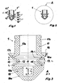
- FIG. 1 shows a central section of a closing member unit according to the prior art, as has been used up to now for a so-called small valve with a single active bellows fold F a *.
- a known locking member unit 1 * ( FIG. 1 ) has a bellows 12 * between a closure part 10 * and a shaft 17 *, which bellows is designed as a so-called bellows and has an "outward" fold geometry 11 *.
- the two inactive bellows folds 14 * and 15 * (F i * 2) open to the surroundings of the closing member unit 1 * and are thus in the medium surrounding the bellows 12 *.
- a closure member unit 1 according to the invention also has, in the same way as that (1 *) according to the prior art, a closure part 10 with a conical seat surface 10a and a shaft 17 with an outer circumferential portion in its end region Fastening groove 17b.
- the sleeve-shaped shaft 17 is continuously provided with a bore 17a which extends into an interior space R of a bellows 12 which integrally connects the closure part 10 and the shaft 17, the latter also being embodied here in the form of a so-called bellows.
- a cylindrical recess 10b is provided in the closure part 10, opening towards the interior R of the bellows 12, into which, for example, a threaded bushing (not shown) for fastening a valve rod (also not shown) is molded.
- the closing part 10 can be displaced in both directions by an axial total stroke H g in both directions with respect to the shaft 17 clamped in the housing of the stroke valve, this mutual axial displacement, on the one hand by a closing stroke H s and on the other hand by an opening stroke H o , is permitted by elastic deformation of the bellows 12.
- a displacement of the closure part 10 by the opening stroke H o causes compression and a displacement by the closing stroke H s causes the bellows 12 to stretch.
- the closing stroke H s and the opening stroke H o together result in the total stroke H g , the closing stroke H s and the opening stroke H o to a stress-free form shape of the closing member unit 1 refer, as shown in figures 2 and 3.
- FIG. 1 A displacement of the closure part 10 by the opening stroke H o causes compression and a displacement by the closing stroke H s causes the bellows 12 to stretch.
- the closing stroke H s and the opening stroke H o together result in the total stroke H g , the closing stroke H s and the opening stroke H o to a stress-free form shape of the closing member unit 1 refer, as shown in figures 2 and 3.
- a related “inward” fold geometry 11 makes the active bellows fold 13 more pressure-resistant to pressure and flow forces from the medium acting on the bellows 12 from the outside.
- the bellows 12, with its flank f 1 on the closure part side facing the closure part 10 is formed directly and, seen in the radial direction, on the closure part 10 so far outwards that, in the case of a fold geometry 11 * according to the prior art (FIG )
- the inactive bellows fold (15 *) required for the medium at this point is omitted.
- flank f 1 on the closure part side merges into the closure part 10 with a convex curvature relative to the surroundings of the bellows 12 and, seen in the radial direction, on the outside.
- the shaft-side flank f 2 facing the shaft 17 is formed directly and, seen in the radial direction, so far outside on the shaft 17 that here, too, that in the closing element unit (1 *) according to the prior art (FIG. 1) in this area the required inactive bellows fold (14 *) facing the medium is eliminated.
- a shaft-side inactive bellows fold 14 (F i 1) results between the shaft 17 and the shaft-side flank f 2 , this inactive bellows fold 14 having an inner space r 2i on the shaft side being opened towards the interior R and therefore not from the bellows 12 surrounding medium is acted upon.
- a particularly advantageous embodiment in this regard is realized in that a connecting region 17c adjoins the shaft-side flank f 2 , which has a convex curvature with respect to the surroundings of the bellows 12, and in that the connecting region 17c in the shaft 17, seen in the radial direction from merges outside.
Landscapes
- Engineering & Computer Science (AREA)
- General Engineering & Computer Science (AREA)
- Mechanical Engineering (AREA)
- Details Of Valves (AREA)
- Lift Valve (AREA)
- Diaphragms And Bellows (AREA)
- Fluid-Damping Devices (AREA)
- Sealing Devices (AREA)
Abstract
Description
- dass ein Balg mit einer Anzahl Fa* = n aktiven Balgfalten auch die gleiche Anzahl n "nach außen liegende" Balgfalten aufweist. Da die Randausführung des Balges zwangsläufig in der vorstehend beschriebenen Weise ausgeführt ist, besitzt dieser Balg mit Fa* = n aktiven Balgfalten in jedem Falle zwei inaktive Balgfalten Fi* (Fi* = 2).
- Ein Balg mit drei aktiven Balgfalten (Fa* = n = 3) besitzt somit drei "nach außen liegende" Balgfalten und Fi* = 2 inaktive Balgfalten am Rand.
- Ein Balg für ein Kleinventil mit einer einzigen aktiven Balgfalte (Fa* = n = 1) besitzt eine "nach außen liegende" Balgfalte und Fi = 2 inaktive Balgfalten am Rand.
| Merkmal | Faltengeometrie | |
| Stand der Stand der Technik | Erfindung | |
| aktive Balgfalten n | Fa* = n | Fa = n |
| reinigungskritische Balgfalten | FRK* = Fa* + 1 = n + 1 | FRK = Fa = n |
| festigkeitskritische Balgfalten | FFK* = Fa* = n | FFK = Fa - 1 = n - 1 |
- Figur 2
- ebenfalls im Mittelschnitt und mit gleichen äußeren Abmessungen wie die Schließglied-Einheit gemäß Figur 1 eine erfindungsgemäße Schließglied-Einheit mit "innen liegender" Faltengeometrie und einer einzigen aktiven Balgfalte Fa (Fa = n = 1) und
- Figur 3
- gleichfalls im Mittelschnitt und im Maßstab 5:1 vergrößert die Schließglied-Einheit gemäß Figur 2.
- 1
- Schließglied-Einheit
- 1*
- Schließglied-Einheit nach dem Stand der Technik
- 10
- Verschlussteil
- 10a
- konische Sitzfläche
- 10b
- zylindrische Ausnehmung
- 11
- Faltengeometrie
- 12
- Balg (insbesondere Faltenbalg oder Wellrohr)
- 13
- aktive Balgfalte(n) Fa
- 14
- gehäuseseitige bzw. schaftseitige inaktive Balgfalte Fi
- 15
- verschlussteilseitige inaktive Balgfalte Fi
- 16
- Anschlussflansch
- 16a
- konische Dichtfläche(n)
- 17
- Schaft
- 17a
- Bohrung
- 17b
- Befestigungsnut
- 17c
- Verbindungsbereich zwischen Schaft 17 und Balg 12
- f
- Flanken der aktiven Balgfalte(n) Fa
- f1
- verschlussteilseitige Flanke
- f2
- schaftseitige Flanke
- r
- Zwischenraum zwischen einer Balgfalte
- ra
- außenseitiger Zwischenraum
- r1i
- verschlussteilseitiger innerer Zwischenraum
- r2i
- schaftseitiger innerer Zwischenraum
- Fa
- aktive Balgfalte(n); Anzahl n
- Fi
- inaktive Balgfalte(n)
- FFK
- festigkeitskritische Balgfalte(n)
- FRK
- reinigungskritische Balgfalte(n)
- Ho
- Öffnungshub, ausgehend von einer spannungsfreien Formgestalt
- Hs
- Schließhub, ausgehend von einer spannungsfreien Formgestalt
- Hg = Ho + Hs
- Gesamthub
- R
- Innenraum des Balges
- *
- als Zusatz: jeweilige Bezeichnung an einer Schließglied-Einheit 1 * nach dem Stand der Technik
Claims (5)
- Schließglied-Einheit für eine balggedichtete Ventilstangendurchführung in einem Hubventil, wobei die Schließglied-Einheit (1) einstückig ausgebildet ist und ein Verschlussteil (10), einen Balg (12), einen Schaft (17) und einen Anschlussflansch (16) umfasst und der Balg (12), der insbesondere als Faltenbalg oder Wellrohr ausgebildet ist und mit wenigstens einer aktiven Balgfalte (Fa) eine Ventilstange koaxial umschließt, die den Verschlussteil (10) mit einem Stellantrieb verbindet, einerseits mit dem Verschlussteil (10) verbunden ist und andererseits in den Schaft (17 übergeht und mit dem Anschlussflansch (16) in einem Gehäuse des Hubventils abgedichtet ist,
dadurch gekennzeichnet,dass das die beiden Flanken (f1, f2) der aktiven Balgfalte(n) (13; Fa) verbindende jeweilige Ende zum Innenraum (R) des Balges (12) hin weist,und dass die verschlussteilseitige Flanke (f1) der dem Verschluss teil (10) unmittelbar benachbarten aktiven Balgfalte (13; Fa) und die schaftseitige Flanke (f2) der dem Schaft (17) unmittelbar benachbarten aktiven Balgfalte (13; Fa) jeweils so weit, in radialer Richtung gesehen, außen am Verschlussteil (10) bzw. am Schaft (17) angeformt sind,dass ein zwischen dem Verschlussteil (10) und der verschlussteilseitigen Flanke (f1) einerseits gebildeter verschlussteilseitiger innerer Zwischenraum (r1i) und ein zwischen dem Schaft (17) und der schaftseitigen Flanke (f2) andererseits gebildeter schaftseitiger innerer Zwischen raum (r2i) jeweils zum Innenraum (R) hin geöffnet sind. - Schließglied-Einheit nach Anspruch 1,
dadurch gekennzeichnet, dass die verschlussteilseitige Flanke (f1) mit einer gegenüber der Umgebung des Balges (12) konvexen Krümmung und, in radialer Richtung gesehen, außenseits bündig in den Verschlussteil (10) übergeht. - Schließglied-Einheit nach Anspruch 1 oder 2,
dadurch gekennzeichnet, dass sich an die schaftseitige Flanke (f2) ein Verbindungsbereich (17c) anschließt, der gegenüber der Umgebung des Balges (12) eine konvexe Krümmung aufweist, und dass der Verbindungsbereich (17c) in den Schaft (17), in radialer Richtung gesehen, von außen übergeht. - Schließglied-Einheit nach Anspruch 3,
dadurch gekennzeichnet, dass an den Verbindungsbereich (17c), in radialer Richtung gesehen, außenseits der Anschlussflansch (16) angeformt ist, der sich kragenförmig zum Schaft (17) hin erweitert. - Schließglied-Einheit nach Anspruch 4,
dadurch gekennzeichnet, dass der Anschlussflansch (16) membranförmig ausgebildet und innen- und außenseits jeweils von einer konischen Dichtfläche (16a) berandet ist.
Applications Claiming Priority (2)
| Application Number | Priority Date | Filing Date | Title |
|---|---|---|---|
| DE10252944 | 2002-11-14 | ||
| DE10252944 | 2002-11-14 |
Publications (2)
| Publication Number | Publication Date |
|---|---|
| EP1420198A1 true EP1420198A1 (de) | 2004-05-19 |
| EP1420198B1 EP1420198B1 (de) | 2011-03-23 |
Family
ID=32115497
Family Applications (1)
| Application Number | Title | Priority Date | Filing Date |
|---|---|---|---|
| EP03025265A Expired - Lifetime EP1420198B1 (de) | 2002-11-14 | 2003-11-06 | Schliessglied-Einheit für eine balggedichtete Ventilstangendurchführung in einem Hubventil |
Country Status (5)
| Country | Link |
|---|---|
| EP (1) | EP1420198B1 (de) |
| AT (1) | ATE503143T1 (de) |
| DE (1) | DE50313565D1 (de) |
| DK (1) | DK1420198T3 (de) |
| ES (1) | ES2358893T3 (de) |
Citations (8)
| Publication number | Priority date | Publication date | Assignee | Title |
|---|---|---|---|---|
| DE2048943A1 (de) * | 1970-10-06 | 1972-04-13 | Richter Kg Armaturen Pumpen | Längenveränderliche balgartige Verkleidung zum Schutz gegen unter Druck stehende aggressive Medien |
| DE2842813A1 (de) * | 1978-09-30 | 1980-04-10 | Schleicher Leonhard | Aseptisches ventil |
| DE9002032U1 (de) * | 1989-08-09 | 1990-06-21 | Richter Chemie-Technik GmbH, 4152 Kempen | PTFE-Faltenbalgabdichtung in Hubventilen |
| EP0508658B1 (de) | 1991-03-27 | 1996-09-11 | Asepco | Keimfreie Ventilkonstruktion |
| EP0862006A2 (de) * | 1997-02-28 | 1998-09-02 | Apv Rosista Gmbh | Vorrichtung zum Verschliessen von Ventilen |
| DE19847294A1 (de) | 1998-04-11 | 1999-10-21 | Tuchenhagen Gmbh | Balg zur Abdichtung einer Ventilstangendurchführung eines Hubventils |
| US6145810A (en) * | 1998-04-14 | 2000-11-14 | Asepco, Inc. | Aseptic valve construction with diaphragm having straight neck |
| DE19957306A1 (de) | 1999-06-08 | 2000-12-21 | Tuchenhagen Gmbh | Schließglied-Einheit für ein aseptisches Doppelsitzventil |
-
2003
- 2003-11-06 AT AT03025265T patent/ATE503143T1/de active
- 2003-11-06 DK DK03025265.4T patent/DK1420198T3/da active
- 2003-11-06 EP EP03025265A patent/EP1420198B1/de not_active Expired - Lifetime
- 2003-11-06 DE DE50313565T patent/DE50313565D1/de not_active Expired - Lifetime
- 2003-11-06 ES ES03025265T patent/ES2358893T3/es not_active Expired - Lifetime
Patent Citations (8)
| Publication number | Priority date | Publication date | Assignee | Title |
|---|---|---|---|---|
| DE2048943A1 (de) * | 1970-10-06 | 1972-04-13 | Richter Kg Armaturen Pumpen | Längenveränderliche balgartige Verkleidung zum Schutz gegen unter Druck stehende aggressive Medien |
| DE2842813A1 (de) * | 1978-09-30 | 1980-04-10 | Schleicher Leonhard | Aseptisches ventil |
| DE9002032U1 (de) * | 1989-08-09 | 1990-06-21 | Richter Chemie-Technik GmbH, 4152 Kempen | PTFE-Faltenbalgabdichtung in Hubventilen |
| EP0508658B1 (de) | 1991-03-27 | 1996-09-11 | Asepco | Keimfreie Ventilkonstruktion |
| EP0862006A2 (de) * | 1997-02-28 | 1998-09-02 | Apv Rosista Gmbh | Vorrichtung zum Verschliessen von Ventilen |
| DE19847294A1 (de) | 1998-04-11 | 1999-10-21 | Tuchenhagen Gmbh | Balg zur Abdichtung einer Ventilstangendurchführung eines Hubventils |
| US6145810A (en) * | 1998-04-14 | 2000-11-14 | Asepco, Inc. | Aseptic valve construction with diaphragm having straight neck |
| DE19957306A1 (de) | 1999-06-08 | 2000-12-21 | Tuchenhagen Gmbh | Schließglied-Einheit für ein aseptisches Doppelsitzventil |
Also Published As
| Publication number | Publication date |
|---|---|
| DE50313565D1 (de) | 2011-05-05 |
| DK1420198T3 (da) | 2011-07-11 |
| EP1420198B1 (de) | 2011-03-23 |
| ES2358893T3 (es) | 2011-05-16 |
| ATE503143T1 (de) | 2011-04-15 |
Similar Documents
| Publication | Publication Date | Title |
|---|---|---|
| DE69213528T3 (de) | Keimfreie Ventilkonstruktion | |
| DE3688332T2 (de) | Balgdichtungsventil. | |
| EP2078892B1 (de) | Vakuum-Ventil mit Dichtring | |
| EP0916046B1 (de) | Doppelsitzventil | |
| EP0124821B1 (de) | Absperrventil mit einem konischen Ventilsitz | |
| DE202016008955U1 (de) | Membran mit geringer Hysterese für ein Ventil | |
| DE2916984A1 (de) | Sitz fuer ein absperrelement eines absperrorgans und absperrorgan mit einem solchen sitz | |
| DE3045215A1 (de) | Klappe | |
| EP2530365B2 (de) | Ventileinsatz für eine Sanitärarmatur | |
| EP3561346B1 (de) | Dichtung, dichtungsanordnung und mehrwege-fluidventil | |
| EP3271623B1 (de) | Hubventil mit drehentkopplungseinrichtung | |
| EP3824207B1 (de) | Hubventil und dichtung | |
| DE68917629T2 (de) | Ventil für Fluide. | |
| EP2203667A1 (de) | Sitzreinigungsfähiges doppelsitzventil und verfahren zur reinigung des sitzreinigungsfähigen doppelsitzventils | |
| EP3699462B1 (de) | Ventilsitz-käfiganordnung | |
| DE19957306C2 (de) | Schließglied-Einheit für ein aseptisches Doppelsitzventil | |
| EP0857901B1 (de) | Ventil | |
| DE60012806T2 (de) | Verbessertes Ventil mit Verschlusskörper mit Dichtungsmittel aus Elastomer | |
| EP1420198B1 (de) | Schliessglied-Einheit für eine balggedichtete Ventilstangendurchführung in einem Hubventil | |
| DE4422478A1 (de) | Durchgangsventil und Verfahren zu seiner Herstellung | |
| DE2206827A1 (de) | Regelventil mit doppeltem Sitz | |
| EP2966331B1 (de) | Hubventil mit membran | |
| WO2005033565A1 (de) | Verteilervorrichtung für ventile | |
| EP3441653A1 (de) | Ventilkörper für ein schrägsitzventil | |
| WO2019020361A1 (de) | Doppelsitzventil mit membran |
Legal Events
| Date | Code | Title | Description |
|---|---|---|---|
| PUAI | Public reference made under article 153(3) epc to a published international application that has entered the european phase |
Free format text: ORIGINAL CODE: 0009012 |
|
| AK | Designated contracting states |
Kind code of ref document: A1 Designated state(s): AT BE BG CH CY CZ DE DK EE ES FI FR GB GR HU IE IT LI LU MC NL PT RO SE SI SK TR |
|
| AX | Request for extension of the european patent |
Extension state: AL LT LV MK |
|
| 17P | Request for examination filed |
Effective date: 20040702 |
|
| AKX | Designation fees paid |
Designated state(s): AT BE BG CH CY CZ DE DK EE ES FI FR GB GR HU IE IT LI LU MC NL PT RO SE SI SK TR |
|
| 17Q | First examination report despatched |
Effective date: 20070727 |
|
| RAP1 | Party data changed (applicant data changed or rights of an application transferred) |
Owner name: GEA TUCHENHAGEN GMBH |
|
| GRAP | Despatch of communication of intention to grant a patent |
Free format text: ORIGINAL CODE: EPIDOSNIGR1 |
|
| GRAS | Grant fee paid |
Free format text: ORIGINAL CODE: EPIDOSNIGR3 |
|
| GRAA | (expected) grant |
Free format text: ORIGINAL CODE: 0009210 |
|
| AK | Designated contracting states |
Kind code of ref document: B1 Designated state(s): AT BE BG CH CY CZ DE DK EE ES FI FR GB GR HU IE IT LI LU MC NL PT RO SE SI SK TR |
|
| REG | Reference to a national code |
Ref country code: GB Ref legal event code: FG4D Free format text: NOT ENGLISH |
|
| REG | Reference to a national code |
Ref country code: CH Ref legal event code: EP Ref country code: CH Ref legal event code: NV Representative=s name: BOHEST AG |
|
| REG | Reference to a national code |
Ref country code: IE Ref legal event code: FG4D |
|
| REG | Reference to a national code |
Ref country code: SE Ref legal event code: TRGR |
|
| REF | Corresponds to: |
Ref document number: 50313565 Country of ref document: DE Date of ref document: 20110505 Kind code of ref document: P |
|
| REG | Reference to a national code |
Ref country code: DE Ref legal event code: R096 Ref document number: 50313565 Country of ref document: DE Effective date: 20110505 |
|
| REG | Reference to a national code |
Ref country code: ES Ref legal event code: FG2A Ref document number: 2358893 Country of ref document: ES Kind code of ref document: T3 Effective date: 20110504 |
|
| REG | Reference to a national code |
Ref country code: NL Ref legal event code: T3 |
|
| REG | Reference to a national code |
Ref country code: DK Ref legal event code: T3 |
|
| PG25 | Lapsed in a contracting state [announced via postgrant information from national office to epo] |
Ref country code: GR Free format text: LAPSE BECAUSE OF FAILURE TO SUBMIT A TRANSLATION OF THE DESCRIPTION OR TO PAY THE FEE WITHIN THE PRESCRIBED TIME-LIMIT Effective date: 20110624 |
|
| PG25 | Lapsed in a contracting state [announced via postgrant information from national office to epo] |
Ref country code: SI Free format text: LAPSE BECAUSE OF FAILURE TO SUBMIT A TRANSLATION OF THE DESCRIPTION OR TO PAY THE FEE WITHIN THE PRESCRIBED TIME-LIMIT Effective date: 20110323 Ref country code: BG Free format text: LAPSE BECAUSE OF FAILURE TO SUBMIT A TRANSLATION OF THE DESCRIPTION OR TO PAY THE FEE WITHIN THE PRESCRIBED TIME-LIMIT Effective date: 20110623 Ref country code: CY Free format text: LAPSE BECAUSE OF FAILURE TO SUBMIT A TRANSLATION OF THE DESCRIPTION OR TO PAY THE FEE WITHIN THE PRESCRIBED TIME-LIMIT Effective date: 20110323 Ref country code: FI Free format text: LAPSE BECAUSE OF FAILURE TO SUBMIT A TRANSLATION OF THE DESCRIPTION OR TO PAY THE FEE WITHIN THE PRESCRIBED TIME-LIMIT Effective date: 20110323 |
|
| PG25 | Lapsed in a contracting state [announced via postgrant information from national office to epo] |
Ref country code: PT Free format text: LAPSE BECAUSE OF FAILURE TO SUBMIT A TRANSLATION OF THE DESCRIPTION OR TO PAY THE FEE WITHIN THE PRESCRIBED TIME-LIMIT Effective date: 20110725 Ref country code: EE Free format text: LAPSE BECAUSE OF FAILURE TO SUBMIT A TRANSLATION OF THE DESCRIPTION OR TO PAY THE FEE WITHIN THE PRESCRIBED TIME-LIMIT Effective date: 20110323 |
|
| PG25 | Lapsed in a contracting state [announced via postgrant information from national office to epo] |
Ref country code: CZ Free format text: LAPSE BECAUSE OF FAILURE TO SUBMIT A TRANSLATION OF THE DESCRIPTION OR TO PAY THE FEE WITHIN THE PRESCRIBED TIME-LIMIT Effective date: 20110323 Ref country code: RO Free format text: LAPSE BECAUSE OF FAILURE TO SUBMIT A TRANSLATION OF THE DESCRIPTION OR TO PAY THE FEE WITHIN THE PRESCRIBED TIME-LIMIT Effective date: 20110323 Ref country code: SK Free format text: LAPSE BECAUSE OF FAILURE TO SUBMIT A TRANSLATION OF THE DESCRIPTION OR TO PAY THE FEE WITHIN THE PRESCRIBED TIME-LIMIT Effective date: 20110323 |
|
| PLBE | No opposition filed within time limit |
Free format text: ORIGINAL CODE: 0009261 |
|
| STAA | Information on the status of an ep patent application or granted ep patent |
Free format text: STATUS: NO OPPOSITION FILED WITHIN TIME LIMIT |
|
| 26N | No opposition filed |
Effective date: 20111227 |
|
| REG | Reference to a national code |
Ref country code: DE Ref legal event code: R097 Ref document number: 50313565 Country of ref document: DE Effective date: 20111227 |
|
| PG25 | Lapsed in a contracting state [announced via postgrant information from national office to epo] |
Ref country code: IT Free format text: LAPSE BECAUSE OF FAILURE TO SUBMIT A TRANSLATION OF THE DESCRIPTION OR TO PAY THE FEE WITHIN THE PRESCRIBED TIME-LIMIT Effective date: 20110323 |
|
| PG25 | Lapsed in a contracting state [announced via postgrant information from national office to epo] |
Ref country code: MC Free format text: LAPSE BECAUSE OF NON-PAYMENT OF DUE FEES Effective date: 20111130 |
|
| REG | Reference to a national code |
Ref country code: AT Ref legal event code: MM01 Ref document number: 503143 Country of ref document: AT Kind code of ref document: T Effective date: 20111106 |
|
| PG25 | Lapsed in a contracting state [announced via postgrant information from national office to epo] |
Ref country code: AT Free format text: LAPSE BECAUSE OF NON-PAYMENT OF DUE FEES Effective date: 20111106 |
|
| PG25 | Lapsed in a contracting state [announced via postgrant information from national office to epo] |
Ref country code: LU Free format text: LAPSE BECAUSE OF NON-PAYMENT OF DUE FEES Effective date: 20111106 |
|
| PG25 | Lapsed in a contracting state [announced via postgrant information from national office to epo] |
Ref country code: TR Free format text: LAPSE BECAUSE OF FAILURE TO SUBMIT A TRANSLATION OF THE DESCRIPTION OR TO PAY THE FEE WITHIN THE PRESCRIBED TIME-LIMIT Effective date: 20110323 |
|
| PG25 | Lapsed in a contracting state [announced via postgrant information from national office to epo] |
Ref country code: HU Free format text: LAPSE BECAUSE OF FAILURE TO SUBMIT A TRANSLATION OF THE DESCRIPTION OR TO PAY THE FEE WITHIN THE PRESCRIBED TIME-LIMIT Effective date: 20110323 |
|
| REG | Reference to a national code |
Ref country code: CH Ref legal event code: PCAR Free format text: NEW ADDRESS: HOLBEINSTRASSE 36-38, 4051 BASEL (CH) |
|
| REG | Reference to a national code |
Ref country code: FR Ref legal event code: PLFP Year of fee payment: 13 |
|
| REG | Reference to a national code |
Ref country code: FR Ref legal event code: PLFP Year of fee payment: 14 |
|
| REG | Reference to a national code |
Ref country code: FR Ref legal event code: PLFP Year of fee payment: 15 |
|
| PGFP | Annual fee paid to national office [announced via postgrant information from national office to epo] |
Ref country code: SE Payment date: 20221122 Year of fee payment: 20 Ref country code: NL Payment date: 20221118 Year of fee payment: 20 Ref country code: IE Payment date: 20221122 Year of fee payment: 20 Ref country code: GB Payment date: 20221123 Year of fee payment: 20 Ref country code: FR Payment date: 20221118 Year of fee payment: 20 Ref country code: ES Payment date: 20221216 Year of fee payment: 20 Ref country code: DK Payment date: 20221122 Year of fee payment: 20 Ref country code: DE Payment date: 20221130 Year of fee payment: 20 |
|
| PGFP | Annual fee paid to national office [announced via postgrant information from national office to epo] |
Ref country code: CH Payment date: 20221124 Year of fee payment: 20 Ref country code: BE Payment date: 20221118 Year of fee payment: 20 |
|
| REG | Reference to a national code |
Ref country code: DE Ref legal event code: R071 Ref document number: 50313565 Country of ref document: DE |
|
| REG | Reference to a national code |
Ref country code: NL Ref legal event code: MK Effective date: 20231105 |
|
| REG | Reference to a national code |
Ref country code: DK Ref legal event code: EUP Expiry date: 20231106 |
|
| REG | Reference to a national code |
Ref country code: CH Ref legal event code: PL |
|
| REG | Reference to a national code |
Ref country code: GB Ref legal event code: PE20 Expiry date: 20231105 Ref country code: ES Ref legal event code: FD2A Effective date: 20231129 |
|
| REG | Reference to a national code |
Ref country code: BE Ref legal event code: MK Effective date: 20231106 |
|
| REG | Reference to a national code |
Ref country code: SE Ref legal event code: EUG |
|
| PG25 | Lapsed in a contracting state [announced via postgrant information from national office to epo] |
Ref country code: GB Free format text: LAPSE BECAUSE OF EXPIRATION OF PROTECTION Effective date: 20231105 |
|
| PG25 | Lapsed in a contracting state [announced via postgrant information from national office to epo] |
Ref country code: ES Free format text: LAPSE BECAUSE OF EXPIRATION OF PROTECTION Effective date: 20231107 |
|
| PG25 | Lapsed in a contracting state [announced via postgrant information from national office to epo] |
Ref country code: IE Free format text: LAPSE BECAUSE OF EXPIRATION OF PROTECTION Effective date: 20231106 Ref country code: GB Free format text: LAPSE BECAUSE OF EXPIRATION OF PROTECTION Effective date: 20231105 Ref country code: ES Free format text: LAPSE BECAUSE OF EXPIRATION OF PROTECTION Effective date: 20231107 |