EP1420918B1 - Procede et outil d'usinage de pieces avec refroidissement - Google Patents
Procede et outil d'usinage de pieces avec refroidissement Download PDFInfo
- Publication number
- EP1420918B1 EP1420918B1 EP02758147A EP02758147A EP1420918B1 EP 1420918 B1 EP1420918 B1 EP 1420918B1 EP 02758147 A EP02758147 A EP 02758147A EP 02758147 A EP02758147 A EP 02758147A EP 1420918 B1 EP1420918 B1 EP 1420918B1
- Authority
- EP
- European Patent Office
- Prior art keywords
- tool
- liquid
- lubricant
- coolant
- machining
- Prior art date
- Legal status (The legal status is an assumption and is not a legal conclusion. Google has not performed a legal analysis and makes no representation as to the accuracy of the status listed.)
- Expired - Lifetime
Links
Images

Classifications
-
- B—PERFORMING OPERATIONS; TRANSPORTING
- B23—MACHINE TOOLS; METAL-WORKING NOT OTHERWISE PROVIDED FOR
- B23Q—DETAILS, COMPONENTS, OR ACCESSORIES FOR MACHINE TOOLS, e.g. ARRANGEMENTS FOR COPYING OR CONTROLLING; MACHINE TOOLS IN GENERAL CHARACTERISED BY THE CONSTRUCTION OF PARTICULAR DETAILS OR COMPONENTS; COMBINATIONS OR ASSOCIATIONS OF METAL-WORKING MACHINES, NOT DIRECTED TO A PARTICULAR RESULT
- B23Q11/00—Accessories fitted to machine tools for keeping tools or parts of the machine in good working condition or for cooling work; Safety devices specially combined with or arranged in, or specially adapted for use in connection with, machine tools
- B23Q11/10—Arrangements for cooling or lubricating tools or work
- B23Q11/1038—Arrangements for cooling or lubricating tools or work using cutting liquids with special characteristics, e.g. flow rate, quality
- B23Q11/1053—Arrangements for cooling or lubricating tools or work using cutting liquids with special characteristics, e.g. flow rate, quality using the cutting liquid at specially selected temperatures
-
- B—PERFORMING OPERATIONS; TRANSPORTING
- B23—MACHINE TOOLS; METAL-WORKING NOT OTHERWISE PROVIDED FOR
- B23B—TURNING; BORING
- B23B51/00—Tools for drilling machines
- B23B51/06—Drills with lubricating or cooling equipment
-
- B—PERFORMING OPERATIONS; TRANSPORTING
- B23—MACHINE TOOLS; METAL-WORKING NOT OTHERWISE PROVIDED FOR
- B23Q—DETAILS, COMPONENTS, OR ACCESSORIES FOR MACHINE TOOLS, e.g. ARRANGEMENTS FOR COPYING OR CONTROLLING; MACHINE TOOLS IN GENERAL CHARACTERISED BY THE CONSTRUCTION OF PARTICULAR DETAILS OR COMPONENTS; COMBINATIONS OR ASSOCIATIONS OF METAL-WORKING MACHINES, NOT DIRECTED TO A PARTICULAR RESULT
- B23Q11/00—Accessories fitted to machine tools for keeping tools or parts of the machine in good working condition or for cooling work; Safety devices specially combined with or arranged in, or specially adapted for use in connection with, machine tools
- B23Q11/10—Arrangements for cooling or lubricating tools or work
- B23Q11/1015—Arrangements for cooling or lubricating tools or work by supplying a cutting liquid through the spindle
-
- B—PERFORMING OPERATIONS; TRANSPORTING
- B23—MACHINE TOOLS; METAL-WORKING NOT OTHERWISE PROVIDED FOR
- B23Q—DETAILS, COMPONENTS, OR ACCESSORIES FOR MACHINE TOOLS, e.g. ARRANGEMENTS FOR COPYING OR CONTROLLING; MACHINE TOOLS IN GENERAL CHARACTERISED BY THE CONSTRUCTION OF PARTICULAR DETAILS OR COMPONENTS; COMBINATIONS OR ASSOCIATIONS OF METAL-WORKING MACHINES, NOT DIRECTED TO A PARTICULAR RESULT
- B23Q11/00—Accessories fitted to machine tools for keeping tools or parts of the machine in good working condition or for cooling work; Safety devices specially combined with or arranged in, or specially adapted for use in connection with, machine tools
- B23Q11/10—Arrangements for cooling or lubricating tools or work
- B23Q11/1038—Arrangements for cooling or lubricating tools or work using cutting liquids with special characteristics, e.g. flow rate, quality
- B23Q11/1061—Arrangements for cooling or lubricating tools or work using cutting liquids with special characteristics, e.g. flow rate, quality using cutting liquids with specially selected composition or state of aggregation
-
- B—PERFORMING OPERATIONS; TRANSPORTING
- B23—MACHINE TOOLS; METAL-WORKING NOT OTHERWISE PROVIDED FOR
- B23B—TURNING; BORING
- B23B51/00—Tools for drilling machines
- B23B51/06—Drills with lubricating or cooling equipment
- B23B51/068—Details of the lubricating or cooling channel
-
- Y—GENERAL TAGGING OF NEW TECHNOLOGICAL DEVELOPMENTS; GENERAL TAGGING OF CROSS-SECTIONAL TECHNOLOGIES SPANNING OVER SEVERAL SECTIONS OF THE IPC; TECHNICAL SUBJECTS COVERED BY FORMER USPC CROSS-REFERENCE ART COLLECTIONS [XRACs] AND DIGESTS
- Y10—TECHNICAL SUBJECTS COVERED BY FORMER USPC
- Y10T—TECHNICAL SUBJECTS COVERED BY FORMER US CLASSIFICATION
- Y10T407/00—Cutters, for shaping
- Y10T407/14—Cutters, for shaping with means to apply fluid to cutting tool
-
- Y—GENERAL TAGGING OF NEW TECHNOLOGICAL DEVELOPMENTS; GENERAL TAGGING OF CROSS-SECTIONAL TECHNOLOGIES SPANNING OVER SEVERAL SECTIONS OF THE IPC; TECHNICAL SUBJECTS COVERED BY FORMER USPC CROSS-REFERENCE ART COLLECTIONS [XRACs] AND DIGESTS
- Y10—TECHNICAL SUBJECTS COVERED BY FORMER USPC
- Y10T—TECHNICAL SUBJECTS COVERED BY FORMER US CLASSIFICATION
- Y10T408/00—Cutting by use of rotating axially moving tool
- Y10T408/44—Cutting by use of rotating axially moving tool with means to apply transient, fluent medium to work or product
- Y10T408/45—Cutting by use of rotating axially moving tool with means to apply transient, fluent medium to work or product including Tool with duct
- Y10T408/453—Cutting by use of rotating axially moving tool with means to apply transient, fluent medium to work or product including Tool with duct and means to move gaseous fluid by application of vacuum
-
- Y—GENERAL TAGGING OF NEW TECHNOLOGICAL DEVELOPMENTS; GENERAL TAGGING OF CROSS-SECTIONAL TECHNOLOGIES SPANNING OVER SEVERAL SECTIONS OF THE IPC; TECHNICAL SUBJECTS COVERED BY FORMER USPC CROSS-REFERENCE ART COLLECTIONS [XRACs] AND DIGESTS
- Y10—TECHNICAL SUBJECTS COVERED BY FORMER USPC
- Y10T—TECHNICAL SUBJECTS COVERED BY FORMER US CLASSIFICATION
- Y10T408/00—Cutting by use of rotating axially moving tool
- Y10T408/44—Cutting by use of rotating axially moving tool with means to apply transient, fluent medium to work or product
- Y10T408/45—Cutting by use of rotating axially moving tool with means to apply transient, fluent medium to work or product including Tool with duct
- Y10T408/455—Conducting channel extending to end of Tool
-
- Y—GENERAL TAGGING OF NEW TECHNOLOGICAL DEVELOPMENTS; GENERAL TAGGING OF CROSS-SECTIONAL TECHNOLOGIES SPANNING OVER SEVERAL SECTIONS OF THE IPC; TECHNICAL SUBJECTS COVERED BY FORMER USPC CROSS-REFERENCE ART COLLECTIONS [XRACs] AND DIGESTS
- Y10—TECHNICAL SUBJECTS COVERED BY FORMER USPC
- Y10T—TECHNICAL SUBJECTS COVERED BY FORMER US CLASSIFICATION
- Y10T408/00—Cutting by use of rotating axially moving tool
- Y10T408/44—Cutting by use of rotating axially moving tool with means to apply transient, fluent medium to work or product
- Y10T408/45—Cutting by use of rotating axially moving tool with means to apply transient, fluent medium to work or product including Tool with duct
- Y10T408/458—Cutting by use of rotating axially moving tool with means to apply transient, fluent medium to work or product including Tool with duct including nozzle
-
- Y—GENERAL TAGGING OF NEW TECHNOLOGICAL DEVELOPMENTS; GENERAL TAGGING OF CROSS-SECTIONAL TECHNOLOGIES SPANNING OVER SEVERAL SECTIONS OF THE IPC; TECHNICAL SUBJECTS COVERED BY FORMER USPC CROSS-REFERENCE ART COLLECTIONS [XRACs] AND DIGESTS
- Y10—TECHNICAL SUBJECTS COVERED BY FORMER USPC
- Y10T—TECHNICAL SUBJECTS COVERED BY FORMER US CLASSIFICATION
- Y10T409/00—Gear cutting, milling, or planing
- Y10T409/30—Milling
- Y10T409/303976—Milling with means to control temperature or lubricate
- Y10T409/304032—Cutter or work
-
- Y—GENERAL TAGGING OF NEW TECHNOLOGICAL DEVELOPMENTS; GENERAL TAGGING OF CROSS-SECTIONAL TECHNOLOGIES SPANNING OVER SEVERAL SECTIONS OF THE IPC; TECHNICAL SUBJECTS COVERED BY FORMER USPC CROSS-REFERENCE ART COLLECTIONS [XRACs] AND DIGESTS
- Y10—TECHNICAL SUBJECTS COVERED BY FORMER USPC
- Y10T—TECHNICAL SUBJECTS COVERED BY FORMER US CLASSIFICATION
- Y10T82/00—Turning
- Y10T82/10—Process of turning
Definitions
- the invention relates to a method for machining or deforming machining of metallic or ceramic workpieces and the use of a preferably submerged tool, wherein during the machining process, an at least predominantly from carbon dioxide (CO 2 ) existing coolant is supplied to the processing site.
- CO 2 carbon dioxide
- the invention further relates to a tool for carrying out the method described above.
- the method described above can be the DE 43 26 517 C2 remove.
- a method for machining of metallic workpieces and ceramic surfaces being cooled during the machining process by supplying a coolant to the processing site, and wherein for cooling a at least predominantly consisting of carbon dioxide coolant jet containing cold gas and snow particles of the processing point is supplied.
- the coolant jet of gaseous CO 2 standing under suitable overpressure is obtained in such a way that the CO 2 gas is first expanded via a slot nozzle or another slot-like opening into an expansion volume formed around this expansion slot and substantially closed off from the surroundings formed by this expansion volume and the outlet opening of the cooling jet and is directed to the area to be cooled.
- the outlet pressure level for the CO 2 before the expansion is at least 50 bar.
- From the DE-B 15 509 lb / 49 a is a method for machining of metallic workpieces known in which during the machining process by supplying a coolant to the processing site is cooled.
- a coolant As a coolant, a liquid jet of CO 2 is used on the workpiece via a nozzle. In the process, the liquid jet of CO 2 impinges on the workpiece at the processing point, producing a precipitate of solid CO 2 .
- the aim is to expand the liquid CO 2 at the point where the tool touches the workpiece.
- the carbon dioxide-based cooling method is dry cooling. Since the carbon dioxide at normal ambient temperature assumes the gaseous state, remain after the cooled processing no coolant residues on the workpiece.
- cryogenic coolant in particular Freon-12 as an example of expandable gas-coolant.
- the coolant passed through a tool is to exit from the tool from a small opening or bore, which bore is intended to control the coolant quantity and is at such a distance from the actual machining point that chips can not have a disturbing influence on the exiting coolant flow ,
- the FR 2 804 492 A1 describes a method for machining or deforming workpieces according to the preamble of independent claim 1, wherein liquid carbon dioxide is used to prevent the use of oil as a lubricant, which is passed through the tool under pressure. In the immediate vicinity of the processing point, the liquid carbon dioxide is expanded out of the tool.
- the DE 10 37 808 B describes the use of carbon dioxide in the form of snow for refrigeration purposes, whereby carbon dioxide snow may also be carried as a suspension in an oil or other liquid.
- the oil complains the fine carbon dioxide particles and has flow characteristics that would not have pure carbonic acid snow.
- the atomization of carbonic acid and oil is done via two nozzles, which are either arranged separately from each other or encased in each other. A merging of oil and carbon dioxide is thus only at the time of atomization.
- the GB 784,504 A1 describes a tool according to the preamble of independent claim 12, wherein liquid carbon dioxide or other cooling medium is passed to the tool tip through a conduit which terminates in a fine nozzle bore.
- the holes are designed as capillary passages in the tips or cutting edges of the tools.
- the invention has for its object to improve the method described above in terms of its tool cooling and to develop a suitable tool for performing the so improved process.
- this object is achieved in that under pressure liquid CO 2 internally passed through the tool and in the immediate vicinity of the actual processing point in this out of the tool by pressure drop to ambient pressure to a cold gas and snow containing Coolant flow is expanded, wherein the expansion takes place through an expansion nozzle forming the coolant outlet from the tool and a liquid lubricant is added to the liquid CO 2 .
- the object of the invention is achieved by at least one internal, designed for the passage of the liquid CO 2 coolant channel, which opens in the vicinity of a tool cutting edge or a tool guide strip in an expansion nozzle for CO 2 evaporation wherein the outlet opening of the expansion nozzle in a small , a regrinding of the tool cutting or - Adjustsang enabling distance before the tool exit is.
- the tool may be, for example, a drill, a thread former, a milling cutter, a boring bar, a reaming tool, turning tables for lathes, or the like. It may be rotating, standing and in particular to dipping tools with geometrically determined and / or undetermined edge.
- the tools can work by machining or material deformation, for example as a thread former, where material is molded by extrusion.
- the cutting tools can be one, two or more cutting tools.
- the term "tool” should also be understood to mean, for example, an annular nozzle used in dry-cleaning (interiors), which during the process wets the broach from the outside or pressurizes it with CO 2 .
- a spindle and / or a tool holder with internal passage of the liquid CO 2 and lossless coupling is used to the tool.
- the liquid CO 2 is then guided lossless through a connecting line, for example by a rotating spindle of a machining center to the tool. Only at the exit near the cutting edge is the expansion realized in the processing area via a nozzle with the narrowest cross section.
- the CO 2 used for cooling is provided, for example, with commercially available gas cylinders and is thus at a temperature of about 20 ° C and a pressure of about 57 bar. The spindle or the tool holder is therefore not affected by the expansion cold.
- Shrink chucks hydraulic chucks or collet chucks for all drills, boring tool or threaded tool shanks or tool bodies, e.g. Monobloc tools (reamers, boring bars) and tool holders for turning operations and broaching tools in question.
- the method according to the invention is particularly suitable for immersing tools in which the methods described in the introduction can not be used at all or only with reduced cooling efficiency. Due to the coolant supply according to the invention directly at the point of action results here a significant reduction of the cutting or deformation temperature.
- the thermal influences are controllable, which has a positive effect on the tool life, the cutting parameters and the workpiece quality, in particular with regard to dimensional accuracy and surface quality.
- control for the coolant flow takes place only during the action time by means of a CO 2 -resistant solenoid valve. It is advantageous if the dimensioning of the expansion nozzle and / or its associated coolant channel is made so that per unit time only required for sufficient cooling amount of liquid CO 2 is expanded.
- the invention proposes, in such cases, the liquid CO 2, the thin liquid lubricant,
- the vaccination with the lubricant can be made immediately before the introduction of the liquid CO 2 stream into the tool in the form of a continuous feed. It is expedient then an intensive mixing, which according to the invention can be ensured by the fact that the CO 2 / lubricant mixture is passed through a sintered plate.
- the liquid, the tool supplied CO 2 stream may have a pressure of about 55 - 63 bar or a temperature of about 18 - 25 ° C.
- the mixing ratio of liquid CO 2 : liquid lubricant can be adjusted to about 30: 1, for example.
- the CO 2 -Expansionsdüse is integrated into a compressed air nozzle, in which forming during operation compressed air jacket opens a lubricant supply.
- such a solution is only suitable for larger tools.
- the expansion nozzle is incorporated into the tool during tooling, e.g. sintered.
- the expansion nozzle can be installed from the outside or else produced by machining or else be introduced into the tool by erosion.
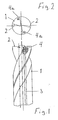
- two for the passage of liquid CO 2 designed coolant channels 3 are passed, which in the vicinity of their associated tool cutting edge 2 each in an expansion nozzle 4 for CO 2 evaporation open.
- the outlet opening 4a of each expansion nozzle 4 is located in a small, a regrinding of the cutting edge 2 enabling distance before the tool outlet of the vaporized CO 2 .
- FIG. 3 shows an embodiment for the supply of a liquid lubricant in the CO 2 stream before entering the tool.
- the liquid CO 2 which may for example have a temperature of 20 ° C and a pressure of 57 bar, via a CO 2 line 6, to which a gas line 7 is still connected, via a rotary feedthrough 8 introduced into a tool 1.
- Dash-dotted line schematically represents a plant 9 for the vaccination of this CO 2 stream with a liquid lubricant.
- This system comprises a bypass-equipped hydraulic pump 10 which feeds lubricant from a lubricant reservoir 11 at a pressure which corresponds at least to the CO 2 pressure in the CO 2 line 6 via a needle valve 12 into the CO 2 line 6.
- a sintered plate 13 is turned on, which is traversed by the CO 2 / lubricant mixture and ensures intensive mixing of the two mixture components.
Landscapes
- Engineering & Computer Science (AREA)
- Mechanical Engineering (AREA)
- Physics & Mathematics (AREA)
- Fluid Mechanics (AREA)
- Auxiliary Devices For Machine Tools (AREA)
- Lubricants (AREA)
- Turning (AREA)
Claims (14)
- Procédé d'usinage de pièces métalliques ou céramiques par enlèvement de copeaux ou par déformation, et d'utilisation d'un outil (1) de préférence plongeant, un réfrigérant consistant au moins majoritairement en du dioxyde de carbone (CO2) étant apporté au poste d'usinage durant le processus d'usinage, du CO2 liquide sous pression étant dirigé en interne au travers de l'outil (1) et étant expansé à sa sortie de l'outil à proximité immédiate du poste d'usinage proprement dit, caractérisé en ce que l'on met en expansion le CO2 liquide sous pression sortant de l'outil (1), par baisse de pression jusqu'à la pression environnante, pour former un flux réfrigérant contenant du gaz et de la neige, l'expansion s'effectuant au travers d'une buse d'expansion (4) formant la sortie de réfrigérant hors de l'outil, et un lubrifiant très liquide étant ajouté au CO2 liquide.
- Procédé selon la revendication 1, caractérisé par l'utilisation d'une broche et/ou d'un porte-outil avec canalisation traversante interne du CO2 liquide et couplage sans perte à l'outil (1).
- Procédé selon la revendication 1 ou 2, caractérisé en ce que le pilotage relatif au flux réfrigérant n'est effectué que durant le temps machine disponible au moyen d'une électrovalve résistante au CO2.
- Procédé selon la revendication 1, 2 ou 3, caractérisé en ce que l'on prévoit le dimensionnement de la buse d'expansion (4) et/ou du canal de réfrigération (3) qui lui est associé, de façon que par unité de temps, l'on mette en expansion seulement la quantité de CO2 liquide requise pour une réfrigération suffisante.
- Procédé selon la revendication 1, caractérisé en ce que l'on utilise une huile de faible viscosité en tant que lubrifiant.
- Procédé selon la revendication 1, caractérisé en ce que l'on ajoute continûment le lubrifiant au flux de CO2 liquide avant son introduction dans l'outil (1).
- Procédé selon la revendication 1, caractérisé en ce que l'on intègre le lubrifiant dans le CO2 liquide par l'intermédiaire d'une vanne à pointeau (11) à une pression correspondant au moins à la pression de CO2.
- Procédé selon la revendication 1, caractérisé en ce que l'on soumet le mélange CO2/lubrifiant à un mélange intensif après l'intégration du lubrifiant dans le CO2 liquide.
- Procédé selon la revendication 8, caractérisé en ce que l'on fait passer le mélange CO2/lubrifiant au travers d'une plaquette frittée (13) en vue de son mélange intensif.
- Procédé selon l'une des revendications précédentes, caractérisé en ce que le flux de CO2 liquide apporté à l'outil (1) présente une pression d'environ 55-63 bar ou une température d'environ 18°C-25°C.
- Procédé selon la revendication 1, caractérisé en ce que l'on ajuste le rapport du mélange CO2 liquide : lubrifiant liquide, à environ 30 : 1.
- Outil pour la mise en oeuvre du procédé selon l'une des revendications précédentes, comprenant au moins un canal de réfrigération (3) interne prévu pour l'acheminement du CO2 liquide, canal qui débouche à proximité d'un tranchant d'outil (2) ou d'une bordure de guidage d'outil, dans une buse d'expansion (4) pour la vaporisation du CO2, caractérisé en ce que l'ouverture de sortie (4a) de la buse d'expansion (4) se trouve devant la sortie de l'outil à une distance réduite permettant un raffûtage du tranchant d'outil (2) ou de la bordure de guidage d'outil.
- Outil selon la revendication 12, caractérisé en ce que la buse d'expansion (4) est usinée dans l'outil (1) lors de la fabrication de l'outil, par exemple formée dans l'outil lors d'un frittage.
- Outil selon la revendication 12 ou 13, caractérisé en ce que la buse d'expansion de CO2 (4) est intégrée dans une buse à air comprimé, une arrivée de lubrifiant débouchant dans la gaine d'air comprimé se formant en fonctionnement par cette buse.
Applications Claiming Priority (3)
| Application Number | Priority Date | Filing Date | Title |
|---|---|---|---|
| DE10140718 | 2001-08-27 | ||
| DE10140718A DE10140718A1 (de) | 2001-08-27 | 2001-08-27 | Verfahren und Werkzeug zur Bearbeitung von Werkstücken mit Kühlung |
| PCT/DE2002/003021 WO2003026843A1 (fr) | 2001-08-27 | 2002-08-16 | Procede et outil d'usinage de pieces avec refroidissement |
Publications (2)
| Publication Number | Publication Date |
|---|---|
| EP1420918A1 EP1420918A1 (fr) | 2004-05-26 |
| EP1420918B1 true EP1420918B1 (fr) | 2009-11-25 |
Family
ID=7695987
Family Applications (1)
| Application Number | Title | Priority Date | Filing Date |
|---|---|---|---|
| EP02758147A Expired - Lifetime EP1420918B1 (fr) | 2001-08-27 | 2002-08-16 | Procede et outil d'usinage de pieces avec refroidissement |
Country Status (6)
| Country | Link |
|---|---|
| US (1) | US7337879B2 (fr) |
| EP (1) | EP1420918B1 (fr) |
| AT (1) | ATE449663T1 (fr) |
| CA (1) | CA2457475C (fr) |
| DE (2) | DE10140718A1 (fr) |
| WO (1) | WO2003026843A1 (fr) |
Families Citing this family (36)
| Publication number | Priority date | Publication date | Assignee | Title |
|---|---|---|---|---|
| US20030110781A1 (en) | 2001-09-13 | 2003-06-19 | Zbigniew Zurecki | Apparatus and method of cryogenic cooling for high-energy cutting operations |
| US20030145694A1 (en) | 2002-02-04 | 2003-08-07 | Zbigniew Zurecki | Apparatus and method for machining of hard metals with reduced detrimental white layer effect |
| US20050214082A1 (en) * | 2004-03-23 | 2005-09-29 | Dasch Jean M | Lubricants in cutting tools for dry machining |
| US7513121B2 (en) | 2004-03-25 | 2009-04-07 | Air Products And Chemicals, Inc. | Apparatus and method for improving work surface during forming and shaping of materials |
| US7634957B2 (en) | 2004-09-16 | 2009-12-22 | Air Products And Chemicals, Inc. | Method and apparatus for machining workpieces having interruptions |
| WO2006065838A2 (fr) * | 2004-12-13 | 2006-06-22 | Cool Clean Technologies, Inc. | Dispositif pour appliquer une composition cryogenique et procede d'utilisation associe |
| EP1828669A2 (fr) * | 2004-12-13 | 2007-09-05 | Cool Clean Technologies, Inc. | Dispositif pour appliquer une composition cryogenique et procede d'utilisation associe |
| US7390240B2 (en) * | 2005-10-14 | 2008-06-24 | Air Products And Chemicals, Inc. | Method of shaping and forming work materials |
| US7434439B2 (en) | 2005-10-14 | 2008-10-14 | Air Products And Chemicals, Inc. | Cryofluid assisted forming method |
| US8074901B2 (en) * | 2005-12-01 | 2011-12-13 | Uniwave, Inc. | Lubricator nozzle and emitter element |
| US20140017016A1 (en) * | 2007-03-30 | 2014-01-16 | Pilepro Llc | Sheet pile components and process for making the same |
| US20090214305A1 (en) * | 2008-02-22 | 2009-08-27 | Waggle James M | Coolant nozzles for milling cutters |
| DE102008021049B3 (de) * | 2008-04-26 | 2009-12-10 | Ex-Cell-O Gmbh | Verfahren zum Kühlen und Schmieren eines Werkzeugs und zum Reinigen der bearbeiteten Fläche |
| US8048830B1 (en) | 2008-06-19 | 2011-11-01 | Cool Clean Technologies, Inc. | Method of forming and using carbonated machining fluid |
| US20090320655A1 (en) * | 2008-06-30 | 2009-12-31 | Marion Billingsley Grant | Machining tool utilizing a supercritical coolant |
| FR2940767B1 (fr) * | 2009-01-08 | 2013-07-05 | Eads Europ Aeronautic Defence | Foret helicoidal a trous de lubrification |
| WO2012129138A2 (fr) * | 2011-03-18 | 2012-09-27 | Cool Clean Technologies, Inc. | Procédé et appareil pour le contrôle thermique dans un procédé d'usinage |
| FR2995808B1 (fr) * | 2012-09-21 | 2015-05-15 | Eads Europ Aeronautic Defence | Outil de percage et dispositif de percage a refroidissement cryogenique et procede de percage d'un empilage de materiaux heterogenes |
| DE102013108787A1 (de) * | 2013-08-14 | 2015-02-19 | Franz Haimer Maschinenbau Kg | Werkzeuganordnung und Werkzeugaufnahme für eine derartige Werkzeuganordnung |
| DE102014000381B4 (de) * | 2014-01-14 | 2018-12-06 | Fraunhofer-Gesellschaft zur Förderung der angewandten Forschung e.V. | Verfahren und Misch-Vorrichtung zum Erzeugen eines mehrphasigen Kühl- und Schmierstoffes für eine Kühlung und Schmierung einer Bearbeitungsvorrichtung |
| CN104096880A (zh) * | 2014-06-20 | 2014-10-15 | 周开雄 | 一种自动排屑的电钻机 |
| CN104308247B (zh) * | 2014-10-22 | 2016-07-27 | 山东大学 | 一种可产生超音速低温气流的可转位式内冷铣刀 |
| US10007246B2 (en) | 2014-12-02 | 2018-06-26 | Caterpillar Inc. | Machining tool utilizing a supercritical coolant |
| EP3199296A1 (fr) * | 2016-01-28 | 2017-08-02 | Brinkmann Pumpen K.H. Brinkmann GmbH & Co. KG | Systeme de lubrifiant refrigerant pour machines-outils |
| PT3248730T (pt) * | 2016-05-27 | 2021-09-15 | Univ Del Pais Vasco Euskal Herriko Unibertsitatea Upv/Ehu | Dispositivo e método para arrefecimento e lubrificação de ferramentas em processos de usinagem |
| US20180043504A1 (en) * | 2016-08-12 | 2018-02-15 | United Technologies Corporation | Machining a cooled region of a body |
| EP3724100A4 (fr) * | 2017-12-12 | 2021-08-25 | Hitachi High-Tech Corporation | Système de lubrification de refroidissement de quantité minimale de r744 adaptatif |
| DE102018202931A1 (de) | 2018-02-27 | 2018-04-19 | Carl Zeiss Smt Gmbh | Vorrichtung und Verfahren zur Montage oder Demontage einer Baugruppe, insbesondere für eine mikrolithographische Projektionsbelichtungsanlage |
| DE102018105150A1 (de) | 2018-03-06 | 2019-09-12 | Ibatec GmbH & Co. KG | Verfahren zur Kühlung und Schmierung eines umformenden oder trennenden Werkzeugs und Vorrichtung zur Durchführung des Verfahrens |
| CN108568700A (zh) * | 2018-06-14 | 2018-09-25 | 广州汇专工具有限公司 | 一种金属切削加工用低温二氧化碳冷却润滑系统 |
| US10786853B2 (en) * | 2018-06-28 | 2020-09-29 | United Technologies Corporation | Cooling system for rotating cutting tools |
| CN109318044A (zh) * | 2018-10-29 | 2019-02-12 | 广州汇专工具有限公司 | 一种超临界二氧化碳供给调控系统 |
| DE102020103670A1 (de) * | 2020-02-12 | 2021-08-12 | Knoll Maschinenbau Gmbh | Verfahren zur Kühlung und Schmierung von Zerspanprozessen |
| DE102021129470A1 (de) | 2021-11-11 | 2023-05-11 | Scherer Engineering Gmbh | Durchbruchvorrichtung |
| CN115742053A (zh) * | 2022-12-04 | 2023-03-07 | 航天材料及工艺研究所 | 一种纤维增强碳化硅基复合材料切削用冷却装置 |
| CN120244043B (zh) * | 2025-06-06 | 2025-08-08 | 固安航天兴邦机械制造有限公司 | 一种航空航天精密螺旋铣孔装置 |
Family Cites Families (20)
| Publication number | Priority date | Publication date | Assignee | Title |
|---|---|---|---|---|
| US397114A (en) * | 1889-02-05 | dolsen | ||
| DE1307808U (fr) | ||||
| DE15509C (de) | R. GRULICH in Halle a. S | Neuerungen an dem Druckregulator für komprimirtes Gas. (P. R. 782, Verbesserung zu P. R. Nr. 782.) | ||
| BE532073A (fr) * | 1952-12-31 | 1900-01-01 | ||
| GB784504A (en) | 1953-10-13 | 1957-10-09 | Nat Res Dev | Improvements in or relating to the machining of metals using liquid carbon dioxide or like medium as a coolant |
| DE1037808B (de) | 1953-11-17 | 1958-08-28 | Distillers Co Yeast Ltd | Kuehlmittel fuer Schneid- und spanabhebende Werkzeuge |
| GB781310A (en) | 1954-10-30 | 1957-08-14 | Distillers Co Yeast Ltd | A method of broaching using carbon dioxide as coolant |
| GB820308A (en) | 1955-02-25 | 1959-09-16 | Nat Res Dev | Improvements in or relating to controlling the supply of carbon dioxide and like coolants to cutting tools |
| US3971114A (en) * | 1972-01-27 | 1976-07-27 | Dudley George M | Machine tool having internally routed cryogenic fluid for cooling interface between cutting edge of tool and workpiece |
| US4829859A (en) * | 1986-08-29 | 1989-05-16 | Ulticon Systems, Inc. | Method of high speed machining |
| US4919232A (en) * | 1989-05-12 | 1990-04-24 | Hugh Lofton | Cold lubricant misting device and method |
| DE4326517C2 (de) * | 1993-08-06 | 1998-06-10 | Linde Ag | Verfahren zur spanenden Bearbeitung von metallischen Werkstücken mit Kühlung |
| FR2724337A1 (fr) * | 1994-09-09 | 1996-03-15 | Anhydride Carbonique Ind | Procede et equipement pour le refroidissement de la zone de travail d'un materiau a usiner |
| US6045300A (en) * | 1997-06-05 | 2000-04-04 | Antoun; Gregory S. | Tool holder with integral coolant passage and replaceable nozzle |
| JP2000210837A (ja) | 1999-01-25 | 2000-08-02 | Yokogawa Kazuhiko | 圧縮した気体を使った加工点冷却加工用ノズル |
| DE19915619A1 (de) | 1999-04-07 | 2000-10-19 | Multimatic Oberflaechentechnik | Verfahren zum Abführen von Zerspanungsprodukten eines zerspanenden Bearbeitungsverfahrens |
| FR2804492B1 (fr) | 2000-02-02 | 2002-06-07 | Carboxyque Francaise | Procede de lubrification mettant en oeuvre du dioxyde de carbone liquide |
| US7513121B2 (en) * | 2004-03-25 | 2009-04-07 | Air Products And Chemicals, Inc. | Apparatus and method for improving work surface during forming and shaping of materials |
| US7634957B2 (en) * | 2004-09-16 | 2009-12-22 | Air Products And Chemicals, Inc. | Method and apparatus for machining workpieces having interruptions |
| WO2006065838A2 (fr) * | 2004-12-13 | 2006-06-22 | Cool Clean Technologies, Inc. | Dispositif pour appliquer une composition cryogenique et procede d'utilisation associe |
-
2001
- 2001-08-27 DE DE10140718A patent/DE10140718A1/de not_active Withdrawn
-
2002
- 2002-08-16 WO PCT/DE2002/003021 patent/WO2003026843A1/fr not_active Ceased
- 2002-08-16 DE DE50214027T patent/DE50214027D1/de not_active Expired - Lifetime
- 2002-08-16 AT AT02758147T patent/ATE449663T1/de not_active IP Right Cessation
- 2002-08-16 EP EP02758147A patent/EP1420918B1/fr not_active Expired - Lifetime
- 2002-08-16 US US10/485,994 patent/US7337879B2/en not_active Expired - Fee Related
- 2002-08-16 CA CA2457475A patent/CA2457475C/fr not_active Expired - Fee Related
Also Published As
| Publication number | Publication date |
|---|---|
| DE50214027D1 (de) | 2010-01-07 |
| CA2457475A1 (fr) | 2003-04-03 |
| CA2457475C (fr) | 2010-02-09 |
| ATE449663T1 (de) | 2009-12-15 |
| DE10140718A1 (de) | 2003-04-03 |
| EP1420918A1 (fr) | 2004-05-26 |
| US7337879B2 (en) | 2008-03-04 |
| WO2003026843A1 (fr) | 2003-04-03 |
| US20040234350A1 (en) | 2004-11-25 |
Similar Documents
| Publication | Publication Date | Title |
|---|---|---|
| EP1420918B1 (fr) | Procede et outil d'usinage de pieces avec refroidissement | |
| DE112008000549B4 (de) | Numerisch gesteuerte Maschine und Verfahren zur Anwendung eines Kühlmittels | |
| DE4309134C2 (de) | Verfahren zur Schmierung und Kühlung von Schneiden und/oder Werkstücken bei zerspanenden Arbeitsprozessen | |
| CH621957A5 (fr) | ||
| WO2015110132A1 (fr) | Porte-lames de tronçonnage et procédé de production | |
| DE3004166A1 (de) | Schneidwerkzeug mit einer kuehlmediumzufuehrvorrichtung | |
| DE102018126753A1 (de) | Rotierendes schneidwerkzeug mit kühlmittelkanälen und verfahren zu dessen herstellung | |
| DE68923396T2 (de) | Werkzeugmaschinenspindel mit Werkzeughalter und Verfahren zum Anwenden dieser Spindel. | |
| DE10222040A1 (de) | Fräswerkzeug | |
| EP4331754A1 (fr) | Dispositif de coupe | |
| DE19728384B4 (de) | Rotierendes Schaftwerkzeug | |
| DE4326517A1 (de) | Verfahren zur spanenden Bearbeitung von metallischen Werkstücken mit Kühlung | |
| EP1242214B1 (fr) | Outil de coupe avec dispositif de réfrigération indirecte d'une plaquette indexable. | |
| DE102020103670A1 (de) | Verfahren zur Kühlung und Schmierung von Zerspanprozessen | |
| DE102014000381B4 (de) | Verfahren und Misch-Vorrichtung zum Erzeugen eines mehrphasigen Kühl- und Schmierstoffes für eine Kühlung und Schmierung einer Bearbeitungsvorrichtung | |
| DE4403327A1 (de) | Reinigungsvorrichtung an mehrachsigen Werkzeugmaschinen | |
| DE102017102883B4 (de) | Verfahren zum Entfernen einer Beschichtung von einem Substrat | |
| EP3311954A1 (fr) | Procédé et dispositif permettant d'acheminement d'un fluide de refroidissement dans un poste d'usinage d'une pièce à usiner métallique | |
| DE102010054401A1 (de) | Bearbeitungsmaschine | |
| EP2164660B1 (fr) | Porte-outil avec plaquette de coupe | |
| DE102004039263A1 (de) | Fräs- oder Bohrwerkzeug mit wenigstens einem Fräskopf oder wenigstens einer Bohrvorrichtung | |
| DE102019209053A1 (de) | Werkzeug zur spanenden Werkstückbearbeitung und Verfahren zur Herstellung sowie zur Aufbereitung des Werkzeugs | |
| DE4326518A1 (de) | Verfahren zur spanenden Bearbeitung von kunststofflichen Werkstücken | |
| DE4218879A1 (de) | Verfahren und Vorrichtung zum Kühlen und/oder Schmieren von Werkzeugen | |
| WO2019145335A1 (fr) | Porte-outil et système porte-outil ainsi que procédé d'usinage |
Legal Events
| Date | Code | Title | Description |
|---|---|---|---|
| PUAI | Public reference made under article 153(3) epc to a published international application that has entered the european phase |
Free format text: ORIGINAL CODE: 0009012 |
|
| 17P | Request for examination filed |
Effective date: 20040121 |
|
| AK | Designated contracting states |
Kind code of ref document: A1 Designated state(s): AT BE BG CH CY CZ DE DK EE ES FI FR GB GR IE IT LI LU MC NL PT SE SK TR |
|
| AX | Request for extension of the european patent |
Extension state: AL LT LV MK RO SI |
|
| RAP1 | Party data changed (applicant data changed or rights of an application transferred) |
Owner name: FORD-WERKE AKTIENGESELLSCHAFT Owner name: MULTIMATIC INTERNATIONAL GMBH |
|
| RAP1 | Party data changed (applicant data changed or rights of an application transferred) |
Owner name: MULTIMATIC INTERNATIONAL GMBH Owner name: FORD-WERKE GMBH |
|
| 17Q | First examination report despatched |
Effective date: 20070823 |
|
| GRAP | Despatch of communication of intention to grant a patent |
Free format text: ORIGINAL CODE: EPIDOSNIGR1 |
|
| GRAS | Grant fee paid |
Free format text: ORIGINAL CODE: EPIDOSNIGR3 |
|
| GRAA | (expected) grant |
Free format text: ORIGINAL CODE: 0009210 |
|
| AK | Designated contracting states |
Kind code of ref document: B1 Designated state(s): AT BE BG CH CY CZ DE DK EE ES FI FR GB GR IE IT LI LU MC NL PT SE SK TR |
|
| REG | Reference to a national code |
Ref country code: GB Ref legal event code: FG4D Free format text: NOT ENGLISH |
|
| REG | Reference to a national code |
Ref country code: CH Ref legal event code: EP |
|
| REG | Reference to a national code |
Ref country code: IE Ref legal event code: FG4D |
|
| REF | Corresponds to: |
Ref document number: 50214027 Country of ref document: DE Date of ref document: 20100107 Kind code of ref document: P |
|
| REG | Reference to a national code |
Ref country code: CH Ref legal event code: NV Representative=s name: BRAUNPAT BRAUN EDER AG Ref country code: CH Ref legal event code: PUEA Owner name: MULTIMATIC INTERNATIONAL GMBH Free format text: MULTIMATIC INTERNATIONAL GMBH#OSNABRUECKER STRASSE 14#49176 HILTER (DE) $ FORD-WERKE GMBH#HENRY-FORD-STRASSE 1#50735 KOELN (DE) -TRANSFER TO- MULTIMATIC INTERNATIONAL GMBH#OSNABRUECKER STRASSE 14#49176 HILTER (DE) |
|
| REG | Reference to a national code |
Ref country code: NL Ref legal event code: VDEP Effective date: 20091125 |
|
| PG25 | Lapsed in a contracting state [announced via postgrant information from national office to epo] |
Ref country code: PT Free format text: LAPSE BECAUSE OF FAILURE TO SUBMIT A TRANSLATION OF THE DESCRIPTION OR TO PAY THE FEE WITHIN THE PRESCRIBED TIME-LIMIT Effective date: 20100325 Ref country code: FI Free format text: LAPSE BECAUSE OF FAILURE TO SUBMIT A TRANSLATION OF THE DESCRIPTION OR TO PAY THE FEE WITHIN THE PRESCRIBED TIME-LIMIT Effective date: 20091125 Ref country code: SE Free format text: LAPSE BECAUSE OF FAILURE TO SUBMIT A TRANSLATION OF THE DESCRIPTION OR TO PAY THE FEE WITHIN THE PRESCRIBED TIME-LIMIT Effective date: 20091125 |
|
| PG25 | Lapsed in a contracting state [announced via postgrant information from national office to epo] |
Ref country code: CY Free format text: LAPSE BECAUSE OF FAILURE TO SUBMIT A TRANSLATION OF THE DESCRIPTION OR TO PAY THE FEE WITHIN THE PRESCRIBED TIME-LIMIT Effective date: 20091125 |
|
| REG | Reference to a national code |
Ref country code: IE Ref legal event code: FD4D |
|
| PG25 | Lapsed in a contracting state [announced via postgrant information from national office to epo] |
Ref country code: NL Free format text: LAPSE BECAUSE OF FAILURE TO SUBMIT A TRANSLATION OF THE DESCRIPTION OR TO PAY THE FEE WITHIN THE PRESCRIBED TIME-LIMIT Effective date: 20091125 Ref country code: EE Free format text: LAPSE BECAUSE OF FAILURE TO SUBMIT A TRANSLATION OF THE DESCRIPTION OR TO PAY THE FEE WITHIN THE PRESCRIBED TIME-LIMIT Effective date: 20091125 Ref country code: DK Free format text: LAPSE BECAUSE OF FAILURE TO SUBMIT A TRANSLATION OF THE DESCRIPTION OR TO PAY THE FEE WITHIN THE PRESCRIBED TIME-LIMIT Effective date: 20091125 Ref country code: BG Free format text: LAPSE BECAUSE OF FAILURE TO SUBMIT A TRANSLATION OF THE DESCRIPTION OR TO PAY THE FEE WITHIN THE PRESCRIBED TIME-LIMIT Effective date: 20100225 Ref country code: ES Free format text: LAPSE BECAUSE OF FAILURE TO SUBMIT A TRANSLATION OF THE DESCRIPTION OR TO PAY THE FEE WITHIN THE PRESCRIBED TIME-LIMIT Effective date: 20100308 Ref country code: IE Free format text: LAPSE BECAUSE OF FAILURE TO SUBMIT A TRANSLATION OF THE DESCRIPTION OR TO PAY THE FEE WITHIN THE PRESCRIBED TIME-LIMIT Effective date: 20091125 |
|
| PG25 | Lapsed in a contracting state [announced via postgrant information from national office to epo] |
Ref country code: SK Free format text: LAPSE BECAUSE OF FAILURE TO SUBMIT A TRANSLATION OF THE DESCRIPTION OR TO PAY THE FEE WITHIN THE PRESCRIBED TIME-LIMIT Effective date: 20091125 Ref country code: CZ Free format text: LAPSE BECAUSE OF FAILURE TO SUBMIT A TRANSLATION OF THE DESCRIPTION OR TO PAY THE FEE WITHIN THE PRESCRIBED TIME-LIMIT Effective date: 20091125 |
|
| PLBE | No opposition filed within time limit |
Free format text: ORIGINAL CODE: 0009261 |
|
| STAA | Information on the status of an ep patent application or granted ep patent |
Free format text: STATUS: NO OPPOSITION FILED WITHIN TIME LIMIT |
|
| PG25 | Lapsed in a contracting state [announced via postgrant information from national office to epo] |
Ref country code: GR Free format text: LAPSE BECAUSE OF FAILURE TO SUBMIT A TRANSLATION OF THE DESCRIPTION OR TO PAY THE FEE WITHIN THE PRESCRIBED TIME-LIMIT Effective date: 20100226 |
|
| 26N | No opposition filed |
Effective date: 20100826 |
|
| REG | Reference to a national code |
Ref country code: CH Ref legal event code: PUE Owner name: GLA-WEL GMBH Free format text: MULTIMATIC INTERNATIONAL GMBH#OSNABRUECKER STRASSE 14#49176 HILTER (DE) -TRANSFER TO- GLA-WEL GMBH#FRIESENWEG 8A#49324 MELLE (DE) |
|
| BERE | Be: lapsed |
Owner name: FORD-WERKE G.M.B.H. Effective date: 20100831 Owner name: MULTIMATIC INTERNATIONAL G.M.B.H. Effective date: 20100831 |
|
| REG | Reference to a national code |
Ref country code: FR Ref legal event code: TQ |
|
| PG25 | Lapsed in a contracting state [announced via postgrant information from national office to epo] |
Ref country code: MC Free format text: LAPSE BECAUSE OF NON-PAYMENT OF DUE FEES Effective date: 20100831 Ref country code: IT Free format text: LAPSE BECAUSE OF FAILURE TO SUBMIT A TRANSLATION OF THE DESCRIPTION OR TO PAY THE FEE WITHIN THE PRESCRIBED TIME-LIMIT Effective date: 20091125 |
|
| PG25 | Lapsed in a contracting state [announced via postgrant information from national office to epo] |
Ref country code: BE Free format text: LAPSE BECAUSE OF NON-PAYMENT OF DUE FEES Effective date: 20100831 |
|
| REG | Reference to a national code |
Ref country code: GB Ref legal event code: 732E Free format text: REGISTERED BETWEEN 20110901 AND 20110907 |
|
| PG25 | Lapsed in a contracting state [announced via postgrant information from national office to epo] |
Ref country code: AT Free format text: LAPSE BECAUSE OF NON-PAYMENT OF DUE FEES Effective date: 20100816 |
|
| PG25 | Lapsed in a contracting state [announced via postgrant information from national office to epo] |
Ref country code: LU Free format text: LAPSE BECAUSE OF NON-PAYMENT OF DUE FEES Effective date: 20100816 |
|
| PG25 | Lapsed in a contracting state [announced via postgrant information from national office to epo] |
Ref country code: TR Free format text: LAPSE BECAUSE OF FAILURE TO SUBMIT A TRANSLATION OF THE DESCRIPTION OR TO PAY THE FEE WITHIN THE PRESCRIBED TIME-LIMIT Effective date: 20091125 |
|
| REG | Reference to a national code |
Ref country code: DE Ref legal event code: R082 Ref document number: 50214027 Country of ref document: DE Representative=s name: GRAMM, LINS & PARTNER GBR, DE |
|
| REG | Reference to a national code |
Ref country code: DE Ref legal event code: R082 Ref document number: 50214027 Country of ref document: DE Representative=s name: GRAMM, LINS & PARTNER GBR, DE Effective date: 20130806 Ref country code: DE Ref legal event code: R081 Ref document number: 50214027 Country of ref document: DE Owner name: GLA-WEL GMBH, DE Free format text: FORMER OWNER: FORD-WERKE GMBH, GLA-WEL GMBH, , DE Effective date: 20130806 Ref country code: DE Ref legal event code: R082 Ref document number: 50214027 Country of ref document: DE Representative=s name: GRAMM, LINS & PARTNER PATENT- UND RECHTSANWAEL, DE Effective date: 20130806 Ref country code: DE Ref legal event code: R081 Ref document number: 50214027 Country of ref document: DE Owner name: GLA-WEL GMBH, DE Free format text: FORMER OWNERS: FORD-WERKE GMBH, 50735 KOELN, DE; GLA-WEL GMBH, 49324 MELLE, DE Effective date: 20130806 |
|
| REG | Reference to a national code |
Ref country code: GB Ref legal event code: 732E Free format text: REGISTERED BETWEEN 20130926 AND 20131002 |
|
| REG | Reference to a national code |
Ref country code: FR Ref legal event code: TP Owner name: GLA-WEL GMBH, DE Effective date: 20131230 |
|
| REG | Reference to a national code |
Ref country code: DE Ref legal event code: R082 Ref document number: 50214027 Country of ref document: DE Representative=s name: GRAMM, LINS & PARTNER PATENT- UND RECHTSANWAEL, DE |
|
| REG | Reference to a national code |
Ref country code: FR Ref legal event code: PLFP Year of fee payment: 14 |
|
| PGFP | Annual fee paid to national office [announced via postgrant information from national office to epo] |
Ref country code: GB Payment date: 20150922 Year of fee payment: 14 |
|
| PGFP | Annual fee paid to national office [announced via postgrant information from national office to epo] |
Ref country code: FR Payment date: 20150824 Year of fee payment: 14 |
|
| PGFP | Annual fee paid to national office [announced via postgrant information from national office to epo] |
Ref country code: CH Payment date: 20151123 Year of fee payment: 14 Ref country code: DE Payment date: 20151029 Year of fee payment: 14 |
|
| REG | Reference to a national code |
Ref country code: DE Ref legal event code: R119 Ref document number: 50214027 Country of ref document: DE |
|
| REG | Reference to a national code |
Ref country code: CH Ref legal event code: PL |
|
| GBPC | Gb: european patent ceased through non-payment of renewal fee |
Effective date: 20160816 |
|
| PG25 | Lapsed in a contracting state [announced via postgrant information from national office to epo] |
Ref country code: LI Free format text: LAPSE BECAUSE OF NON-PAYMENT OF DUE FEES Effective date: 20160831 Ref country code: CH Free format text: LAPSE BECAUSE OF NON-PAYMENT OF DUE FEES Effective date: 20160831 |
|
| REG | Reference to a national code |
Ref country code: FR Ref legal event code: ST Effective date: 20170428 |
|
| PG25 | Lapsed in a contracting state [announced via postgrant information from national office to epo] |
Ref country code: FR Free format text: LAPSE BECAUSE OF NON-PAYMENT OF DUE FEES Effective date: 20160831 Ref country code: GB Free format text: LAPSE BECAUSE OF NON-PAYMENT OF DUE FEES Effective date: 20160816 Ref country code: DE Free format text: LAPSE BECAUSE OF NON-PAYMENT OF DUE FEES Effective date: 20170301 |