EP4331754A1 - Dispositif de coupe - Google Patents
Dispositif de coupe Download PDFInfo
- Publication number
- EP4331754A1 EP4331754A1 EP23180338.8A EP23180338A EP4331754A1 EP 4331754 A1 EP4331754 A1 EP 4331754A1 EP 23180338 A EP23180338 A EP 23180338A EP 4331754 A1 EP4331754 A1 EP 4331754A1
- Authority
- EP
- European Patent Office
- Prior art keywords
- clamping
- holder
- tool holder
- cutting device
- section
- Prior art date
- Legal status (The legal status is an assumption and is not a legal conclusion. Google has not performed a legal analysis and makes no representation as to the accuracy of the status listed.)
- Pending
Links
Images

Classifications
-
- B—PERFORMING OPERATIONS; TRANSPORTING
- B23—MACHINE TOOLS; METAL-WORKING NOT OTHERWISE PROVIDED FOR
- B23B—TURNING; BORING
- B23B27/00—Tools for turning or boring machines; Tools of a similar kind in general; Accessories therefor
- B23B27/14—Cutting tools of which the bits or tips or cutting inserts are of special material
- B23B27/16—Cutting tools of which the bits or tips or cutting inserts are of special material with exchangeable cutting bits or cutting inserts, e.g. able to be clamped
- B23B27/1666—Cutting tools of which the bits or tips or cutting inserts are of special material with exchangeable cutting bits or cutting inserts, e.g. able to be clamped with plate-like cutting inserts clamped by a clamping member acting almost perpendicularly on chip-forming plane
-
- B—PERFORMING OPERATIONS; TRANSPORTING
- B23—MACHINE TOOLS; METAL-WORKING NOT OTHERWISE PROVIDED FOR
- B23B—TURNING; BORING
- B23B27/00—Tools for turning or boring machines; Tools of a similar kind in general; Accessories therefor
- B23B27/04—Cutting-off tools
-
- B—PERFORMING OPERATIONS; TRANSPORTING
- B23—MACHINE TOOLS; METAL-WORKING NOT OTHERWISE PROVIDED FOR
- B23B—TURNING; BORING
- B23B27/00—Tools for turning or boring machines; Tools of a similar kind in general; Accessories therefor
- B23B27/10—Cutting tools with special provision for cooling
-
- B—PERFORMING OPERATIONS; TRANSPORTING
- B23—MACHINE TOOLS; METAL-WORKING NOT OTHERWISE PROVIDED FOR
- B23B—TURNING; BORING
- B23B29/00—Holders for non-rotary cutting tools; Boring bars or boring heads; Accessories for tool holders
- B23B29/04—Tool holders for a single cutting tool
- B23B29/043—Tool holders for a single cutting tool with cutting-off, grooving or profile cutting tools, i.e. blade- or disc-like main cutting parts
-
- B—PERFORMING OPERATIONS; TRANSPORTING
- B23—MACHINE TOOLS; METAL-WORKING NOT OTHERWISE PROVIDED FOR
- B23B—TURNING; BORING
- B23B2205/00—Fixation of cutting inserts in holders
- B23B2205/02—Fixation using an elastically deformable clamping member
-
- B—PERFORMING OPERATIONS; TRANSPORTING
- B23—MACHINE TOOLS; METAL-WORKING NOT OTHERWISE PROVIDED FOR
- B23B—TURNING; BORING
- B23B2205/00—Fixation of cutting inserts in holders
- B23B2205/12—Seats for cutting inserts
-
- B—PERFORMING OPERATIONS; TRANSPORTING
- B23—MACHINE TOOLS; METAL-WORKING NOT OTHERWISE PROVIDED FOR
- B23B—TURNING; BORING
- B23B29/00—Holders for non-rotary cutting tools; Boring bars or boring heads; Accessories for tool holders
- B23B29/04—Tool holders for a single cutting tool
- B23B29/046—Tool holders for a single cutting tool with an intermediary toolholder
-
- B—PERFORMING OPERATIONS; TRANSPORTING
- B23—MACHINE TOOLS; METAL-WORKING NOT OTHERWISE PROVIDED FOR
- B23B—TURNING; BORING
- B23B29/00—Holders for non-rotary cutting tools; Boring bars or boring heads; Accessories for tool holders
- B23B29/04—Tool holders for a single cutting tool
- B23B29/08—Tool holders equipped with grooves arranged crosswise to the longitudinal direction for setting the cutting tool
Definitions
- the invention relates to a cutting device for the machining of workpieces, with a tool holder having a holder longitudinal axis, the holder having a holder top and a holder bottom, each of which extends along the holding longitudinal axis and has a holder end face, which is oriented transversely to the holder's longitudinal axis, the tool holder having a cutting insert receptacle for receiving a cutting insert, which is delimited by a first and a second clamping surface opposite this, one of which is formed on a clamping finger which holds the cutting insert between one Clamping position clamping surfaces and a release position releasing the cutting insert is movably mounted, and the clamping finger forms the end face of the tool holder with the holder end face formed thereon.
- Cutting devices of this type have been known for a long time and are used in particular in the turning of workpieces. Such cutting devices are used there, for example, in CNC lathes.
- a special case of turning workpieces is so-called parting off, in which a bar is cut off using the cutting device to complete a workpiece.
- the material costs are a significant part of the total costs of the workpiece.
- thin, long cutting devices also known as parting bars or blades, are commonly used, which in some cases can result in vibration and poor surface quality.
- the cutting device has a tool holder which has a holder longitudinal axis.
- the tool holder is equipped with a suitable cutting insert.
- the tool holder is then attached to a base holder, which in turn is attached to an interface on the lathe.
- the turning process for example parting off, is carried out by moving or advancing the cutting device to the rotating workpiece along a feed direction that runs parallel to the longitudinal axis of the holder. Such operations are also referred to as turning operations along the X axis.
- the EP 3 357 613 A1 recommend using the Y axis for parting.
- the feed movement is at an angle of 90° to the longitudinal axis of the holder.
- the force acting on the cutting tool, especially on the piercing blade, is more favorable here and acts over a larger part into the tool holder than when turning in the X direction.
- the cutting devices used for turning machining along the Y axis have the clamping finger which is used to clamp the cutting insert in the assigned cutting insert receptacle on the tool holder, arranged at the front end of the tool holder.
- the clamping finger is usually significantly shorter. In the worst case scenario, this can lead to inadequate clamping of the cutting insert.
- the object of the invention is therefore to create a cutting device of the type mentioned at the beginning, which ensures reliable and trouble-free machining results on the workpiece to be machined during turning or grooving machining along the Y axis.
- the cutting device according to the invention is characterized in that the clamping finger is assigned at least one clamping element, which is designed separately from the tool holder and belongs to the cutting device and engages an interface on the clamping finger, by actuating which the clamping finger can be moved into the clamping position or release position.
- a separate clamping element is used, which is attached to an interface of the clamping finger itself is stored.
- the clamping element can be moved between a clamping position and a release position, wherein the clamping position of the clamping element correlates with the clamping position of the clamping finger, while the release position of the clamping element correlates with the release position of the clamping finger.
- the clamping force is introduced via the clamping screw directly on the clamping finger and the clamping element, in its clamping position, ensures a consistently good clamping force between the clamping surfaces and the associated cutting insert.
- the at least one clamping element is designed as a clamping screw, which is accommodated in a bore having a bore axis, the bore passing through the clamping finger and ending in a base section of the tool holder.
- the hole in the tool holder expediently has an internal thread for screwing to the external thread formed on the clamping screw.
- the hole is expediently designed as a blind hole and ends in the base section of the tool holder.
- the bore axis of the bore is aligned essentially parallel to the holder's longitudinal axis. While the feed direction is aligned perpendicular to the longitudinal axis of the holder when the cutting device is in use, the bore axis runs parallel to the longitudinal axis of the holder. This results in a very good introduction of the clamping force onto the cutting insert.
- a separating slot extending from the cutting insert receptacle is formed in the tool holder and separates the clamping finger from the base section of the tool holder.
- the clamping screw expediently passes through the separating slot.
- the clamping finger and the base section are connected to one another in one piece via a connecting section formed between the slot end of the separating slot and the underside of the holder.
- the connecting section forms a type of pivot bearing around which the clamping finger can be pivoted between the clamping position and the release position if the clamping element, in particular the clamping screw, is actuated.
- the interface on the clamping finger has a countersink for receiving a screw head of the clamping screw.
- the clamping screw can be, for example, a countersunk screw.
- the clamping surfaces are aligned at an angle to the holder's longitudinal axis, in particular at an angle greater than 45°.
- the tool holder has a tool holder coolant channel system with a plurality of coolant channels, the coolant channel system having at least one, in particular several, coolant outlet openings through which coolant can be conducted to the cutting insert during machining.
- the coolant channel system having at least one, in particular several, coolant outlet openings through which coolant can be conducted to the cutting insert during machining.
- coolant outlet opening is expediently aligned in such a way that escaping coolant, which is a coolant and lubricant or cooling lubricant, is directed onto the cutting surface of the cutting insert.
- the coolant outlet opening in question is aligned in such a way that material chips from the workpiece located on the cutting surface are washed away.
- a further coolant outlet opening is provided, which is arranged in such a way that coolant reaches the area of the open surface of the cutting insert, which makes it possible to cool the cutting surface and also the open surface at the same time.
- the further coolant outlet opening may be formed on the tool holder, for example in the area of the top of the holder and/or on a base holder.
- the clamping finger has a sword-like clamping section equipped with the clamping surface, which has a clamping section width and a clamping section length extending in a holder height direction perpendicular to the holder's longitudinal axis, and the clamping finger has a has a bearing section connected to the clamping section, which has a bearing section width and a bearing section length.
- the bearing section width of the bearing section is larger than the clamping section width Clamping section, in particular the ratio of bearing section width to clamping section width is two to four.
- the clamping section length of the Ar clamping section of the clamping finger is expediently greater than the bearing section length of the bearing section of the clamping finger.
- the cutting device has a base holder to which the tool holder can be attached or is attached via a fastening device.
- the fastening device has a plurality of fastening holes formed on the tool holder and fastening elements passing through the fastening holes, in particular fastening screws, the fastening holes being arranged one behind the other along the holder's longitudinal axis, preferably at least two of the fastening holes being aligned with one another.
- the cutting device has a cutting insert inserted in the cutting insert receptacle, in particular in the form of a cutting plate.
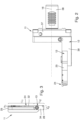
- the Figures 1 to 3 show a preferred exemplary embodiment of the cutting device 11 according to the invention.
- the cutting device 11 is shown here purely by way of example in an embodiment which shows a base holder 12 which can be used in a processing machine for machining and can be fastened there.
- a tool holder 13 is in turn clamped to the base holder 12 and is used to hold a cutting insert 14 for machining workpieces 15.
- the combination of tool holder 13 and cutting insert 14 can also be referred to as a cutting tool.
- the cutting device 11 is intended for turning workpieces 15, which can be rods, for example.
- the one in is particularly suitable Figure 1 tool holder 13 shown with a corresponding cutting insert 14 for parting off workpieces 15, so that the tool holder 13 could also be referred to as a parting blade in this case.
- the tool holder 13 equipped with the cutting insert 14 is attached to a base holder 12, which in turn is accommodated in a receptacle of the processing machine, in particular a lathe.
- the tool holder 13 has a holder longitudinal axis 16, along which a holder top 17 or upper edge and, aligned opposite thereto, a holder underside 18 or lower edge extend. Further the tool holder 13 has a holder end face 19 which is aligned transversely to the holder longitudinal axis 16.
- the tool holder 13 has a cutting insert receptacle 20 for receiving the cutting attachment 14.
- a relatively narrow cutting insert 20 which in this case is also called Cutting plate could be called.
- the cutting insert receptacle 20 could therefore also be referred to as an insert seat.
- the cutting insert receptacle 20 defines a receiving space 21 for the cutting insert, the receiving space 21 being delimited by a first and a second clamping surface 22, 23 opposite this.
- clamping surfaces 22, 23 and the corresponding counter-clamping surfaces formed on the cutting insert 14 are expediently designed in the manner of a prism, that is to say a clamping groove and a clamping projection are formed on the clamping surface and the associated counter-clamping surface, which are formed in the manner of a groove when clamping and spring interlock.
- clamping surfaces 22, 23 are aligned obliquely, in particular at an angle of greater than 45°, preferably greater than 80°, relative to the holder longitudinal axis 16.
- An essential element of the tool holder 13 is a clamping finger 24, which is between a clamping position clamping the cutting insert 14 to the clamping surfaces 22, 23 and a the cutting insert 14 is movably mounted in the release position.
- the clamping finger is connected in one piece to a base section 25 of the tool holder 13.
- the base section 25 on the clamping finger is separated from one another by a separating slot 26 extending from the cutting insert receptacle 20.
- the separating slot also runs obliquely to the holder's longitudinal axis 16, preferably at an angle greater than 45°.
- the clamping finger 24 and the base section 25 are - as mentioned - connected to one another in one piece via a connecting section 28 formed between the slot end 27 of the separating slot 26 and the holder underside 18.
- An important aspect is that the clamping finger 24 closes the end face of the tool holder 13 with the holder end face 19 formed thereon.
- the clamping finger 24 also extends with its longitudinal extent obliquely to the longitudinal axis of the holder, in particular at an angle of greater than 45°.
- the connecting section 28 forms a type of pivot bearing for the clamping finger 24, which can pivot about this pivot bearing to transfer it from the clamping position to the release position or vice versa.
- An important aspect is that the initiation of the clamping movement from the release position of the clamping finger 24 into the clamping position clamping the cutting insert to the clamping surfaces 22, 23 is carried out by means of at least one clamping element, which is designed separately from the tool holder 13 and belongs to the cutting device 11 and engages an interface on the clamping finger 24 29 is carried out, by actuating which the clamping finger 24 can be moved into the clamping position or release position.
- the at least one clamping element 29 is designed as a clamping screw which is received in a bore 31 having a bore axis 30, the bore 31 passing through the clamping finger 24 and ending in the base section 25 of the tool holder 13.
- the bore axis 30 of the bore 31 is aligned essentially parallel to the holder longitudinal axis 16.
- the clamping screw passes through the clamping finger 24, the separating slot 26 and ends in the hole 31 designed as a blind lock hole in the base section 25 of the tool holder 13.
- a bore section of the bore 31 located in the base section 25 expediently has an internal thread (not shown) which can be screwed to an external thread of the clamping screw.
- the clamping finger 24 has different functional sections.
- the clamping finger 24 has a sword-like clamping section 32 ( Figure 3 ), which has a clamping section width b 1 and a clamping section length l 1 extending in a holder height direction 33 lying perpendicular to the holder longitudinal axis 16 .
- the clamping finger 24 has a bearing section 34 connected to the clamping section 32, which has a bearing section width b 2 and a bearing section length l 2 .
- the bearing section width l 2 of the bearing section 34 is larger than the clamping section width of the sword-like clamping section 32.
- the ratio of the bearing section width b 2 to the clamping section width b 1 is expediently two to four.
- the bearing section 34 with its bearing section width b 2 is designed such that the interface for the clamping screw is formed thereon.
- the bore 31 therefore runs through the bearing section 34 of the clamping finger 24.
- the clamping section length l 1 is greater than the bearing section length l 2 , in particular the ratio of the clamping section length to the bearing section length l 2 through l 1 is 2 to 4.
- the mouth of the bore on the bearing section 34 of the clamping finger 14 can be designed with a countersink 35 for receiving a screw head of the clamping screw.
- the clamping screw can be designed as a countersunk screw.
- the tool holder 13 is attached to the base holder 12 via a fastening device 36.
- the base holder 12 in the example shown is designed in the manner of an angle piece, and has a base holder base section 37, on the back of which a fastening element, in particular fastening pin 38, is formed, the fastening pin 38 being for fastening to an associated bearing holder or a magazine on the processing machine, in particular a lathe.
- a base holder bearing section 39 for supporting the tool holder 13 is formed on the front side of the base holder base section 37 opposite the rear side equipped with the fastening pin 38.
- the fastening device 36 used to fasten the tool holder 13 to the base holder bearing section 39 has a plurality of fastening holes 40a, 40b formed on the tool holder 13 and Fastening elements 41a, 41b, in particular fastening screws, passing through the fastening holes 40a, 40b, the fastening holes 40a, 40b being arranged one behind the other along the holder longitudinal axis 16.
- two fastening holes 40a, 40b are formed in the tool holder 13, which are expediently aligned with one another along the holder's longitudinal axis 16.
- a fastening slot 42 is formed on the base holder bearing section 39, which enables the tool holder 13 to be fastened in any position along the slot length of the fastening slot 42 relative to the base holder 12.
- the cutting device has a coolant supply device 43, which in the example shown consists of a base holder coolant channel system 44 and a tool holder coolant channel system 45.
- the basic holder coolant channel system has 44 coolant supply connections via which coolant can be supplied from an external coolant source. Coolant then enters a central channel 46 and from there into distribution channels, the exemplary embodiment shown being three distribution channels 47a, 47b, 47c.
- the first distribution channel 47a runs completely in the base holder 12 and opens into a coolant nozzle 48, which is expediently pivotably mounted on the base holder bearing section 39. Due to the pivotability of the coolant nozzle 48, the coolant jet can be adjusted in a targeted manner, so that a targeted supply of coolant to the cooling areas, which are in particular the cutting edge, the cutting surface and that of the cutting insert, is possible.
- the second and third distribution channels 47b, 47c end in the area of the front edge of the base holder bearing section 39 by means of a coolant transfer interface 49b, 49c.
- a coolant transfer interface 49b, 49c At the respective coolant transfer interfaces 49a, 49b there is a connection to cooling channels of the tool holder coolant channel system 45 formed in the tool holder 13.
- the second distribution channel 47b is connected to a first cooling channel 50 in the tool holder 13 via the assigned coolant transfer interface 49b.
- This first cooling channel 50 runs essentially parallel to the holder longitudinal axis 16 and opens out at a step formed on the holder top 17 by means of a first coolant outlet opening 51.
- Escaping coolant can then flow in a direction essentially parallel to the holder longitudinal axis 16 in the direction of the cutting insert 14 and from there reaches the open surface or cutting edge of the cutting insert 14.
- the third distribution channel 47c in the base holder 12 is connected to a second one, also via one of the coolant transfer channels. Interfaces connected to the second coolant channel 52 in the tool holder 13.
- the diameter of the second coolant channel in the tool holder 12 is relatively small, since it runs in the area of the sword-like clamping section 32 of the clamping finger 24.
- the second coolant channel 52 has a first channel section 53, which runs from the coolant transfer interface 49c towards the underside of the holder 18. It is aligned so that it passes under the blind hole in the tool holder.
- a second channel section 54 adjoins the first channel section of the second coolant channel 52, which runs essentially parallel to the underside of the holder 17. What is important here is that this second channel section 54 runs through the connecting section 28 which is formed between the slot end of the separating slot 26 and the holder underside 18.
- a third channel section 55 branches off from the second channel section 54, which runs essentially in the longitudinal direction of the clamping finger 24 through the clamping section 32 of the clamping finger, changes its direction again in the example shown and on a clamping finger end face 56 of the clamping finger 24 through a further coolant -Outlet opening 57 opens out. From there, coolant can flow onto the cutting surface and the cutting edge of the cutting insert 14.
- the cutting device 11 described is used in the example shown for turning workpieces 13 by means of parting off, the Y axis being used.
- the cutting device 11 is therefore delivered to the workpiece 15 to be machined along a feed direction that is at a 90 ° angle to the holder longitudinal axis 16.
- the clamping element 29 in the form of the clamping screw ensures reliable clamping of the cutting insert 14 on the assigned seat, whereby high cutting values and short processing times can be achieved.
Landscapes
- Engineering & Computer Science (AREA)
- Mechanical Engineering (AREA)
- Cutting Tools, Boring Holders, And Turrets (AREA)
Applications Claiming Priority (1)
| Application Number | Priority Date | Filing Date | Title |
|---|---|---|---|
| DE102022121948.8A DE102022121948A1 (de) | 2022-08-31 | 2022-08-31 | Schneidvorrichtung |
Publications (1)
| Publication Number | Publication Date |
|---|---|
| EP4331754A1 true EP4331754A1 (fr) | 2024-03-06 |
Family
ID=86904231
Family Applications (1)
| Application Number | Title | Priority Date | Filing Date |
|---|---|---|---|
| EP23180338.8A Pending EP4331754A1 (fr) | 2022-08-31 | 2023-06-20 | Dispositif de coupe |
Country Status (2)
| Country | Link |
|---|---|
| EP (1) | EP4331754A1 (fr) |
| DE (1) | DE102022121948A1 (fr) |
Cited By (2)
| Publication number | Priority date | Publication date | Assignee | Title |
|---|---|---|---|---|
| JP7752835B1 (ja) * | 2024-10-01 | 2025-10-14 | 株式会社タンガロイ | ヘッド交換式切削工具 |
| WO2026026861A1 (fr) | 2024-07-31 | 2026-02-05 | Safran Aircraft Engines Suzhou Co., Ltd. | Outil de coupe |
Families Citing this family (1)
| Publication number | Priority date | Publication date | Assignee | Title |
|---|---|---|---|---|
| DE102022121948A1 (de) | 2022-08-31 | 2024-02-29 | Karl-Heinz Arnold Gmbh | Schneidvorrichtung |
Citations (6)
| Publication number | Priority date | Publication date | Assignee | Title |
|---|---|---|---|---|
| US2940160A (en) * | 1956-06-19 | 1960-06-14 | Raymond E Novkov | Combination cut-off and chamfering tool |
| US3523349A (en) * | 1968-03-04 | 1970-08-11 | Bernard M Pollington | Cutting tool assembly |
| DE2653222A1 (de) * | 1975-12-08 | 1977-06-23 | Iscar Ltd | Schneidwerkzeug |
| US6715386B2 (en) * | 2001-05-18 | 2004-04-06 | Plansee Tizit Aktiengesellschaft | Turning method |
| EP3357613A1 (fr) | 2017-02-03 | 2018-08-08 | Sandvik Intellectual Property AB | Lame four outil de rainurage en métaux |
| DE102022121948A1 (de) | 2022-08-31 | 2024-02-29 | Karl-Heinz Arnold Gmbh | Schneidvorrichtung |
Family Cites Families (3)
| Publication number | Priority date | Publication date | Assignee | Title |
|---|---|---|---|---|
| DE8804365U1 (de) * | 1988-03-31 | 1988-05-11 | Kemmer, Klaus, Ing.(grad.), 7277 Wildberg | Schneid- und Abstechwerkzeug |
| US8827598B2 (en) * | 2011-11-22 | 2014-09-09 | Kennametal Inc. | Cutting assembly with enhanced coolant delivery |
| EP3867001A1 (fr) * | 2018-10-17 | 2021-08-25 | Hartmetall-Werkzeugfabrik Paul Horn GmbH | Porte-outil et outil muni d'un tel porte-outil |
-
2022
- 2022-08-31 DE DE102022121948.8A patent/DE102022121948A1/de active Pending
-
2023
- 2023-06-20 EP EP23180338.8A patent/EP4331754A1/fr active Pending
Patent Citations (6)
| Publication number | Priority date | Publication date | Assignee | Title |
|---|---|---|---|---|
| US2940160A (en) * | 1956-06-19 | 1960-06-14 | Raymond E Novkov | Combination cut-off and chamfering tool |
| US3523349A (en) * | 1968-03-04 | 1970-08-11 | Bernard M Pollington | Cutting tool assembly |
| DE2653222A1 (de) * | 1975-12-08 | 1977-06-23 | Iscar Ltd | Schneidwerkzeug |
| US6715386B2 (en) * | 2001-05-18 | 2004-04-06 | Plansee Tizit Aktiengesellschaft | Turning method |
| EP3357613A1 (fr) | 2017-02-03 | 2018-08-08 | Sandvik Intellectual Property AB | Lame four outil de rainurage en métaux |
| DE102022121948A1 (de) | 2022-08-31 | 2024-02-29 | Karl-Heinz Arnold Gmbh | Schneidvorrichtung |
Cited By (3)
| Publication number | Priority date | Publication date | Assignee | Title |
|---|---|---|---|---|
| WO2026026861A1 (fr) | 2024-07-31 | 2026-02-05 | Safran Aircraft Engines Suzhou Co., Ltd. | Outil de coupe |
| WO2026025324A1 (fr) * | 2024-07-31 | 2026-02-05 | Safran Aircraft Engines Suzhou Co., Ltd. | Outil de coupe |
| JP7752835B1 (ja) * | 2024-10-01 | 2025-10-14 | 株式会社タンガロイ | ヘッド交換式切削工具 |
Also Published As
| Publication number | Publication date |
|---|---|
| DE102022121948A1 (de) | 2024-02-29 |
Similar Documents
| Publication | Publication Date | Title |
|---|---|---|
| EP4331754A1 (fr) | Dispositif de coupe | |
| DE69304288T2 (de) | Nutenschneideinsatz | |
| EP3519130B1 (fr) | Lame de separation de tournage | |
| DE19719893A1 (de) | Reib- und Senk-Schneidwerkzeug mit Kühlmittelzufuhr | |
| EP3501701A1 (fr) | Système d'outillage et procédé d'usinage par tournage | |
| DE102008040562A1 (de) | Werkzeug mit axialer Einstellbarkeit | |
| DE102009060046A1 (de) | System aus Werkzeugaufnahme und verstellbaren Werkzeug mit interner Kühlschmiermediumzufuhr | |
| DE10331077B3 (de) | Drehmeißelhalter | |
| DE10339518A1 (de) | Bohrwerkzeug mit Wechselschneidplatten sowie Wechselschneidplatten für ein solches Bohrwerkzeug | |
| DE4212709C2 (de) | Werkzeug mit einem austauschbaren, einen zylindrischen Schaft aufweisenden Schneidkörper für die spanabhebende Formgebung, vornehmlich in der Metallbearbeitung | |
| DE69213229T2 (de) | Werkzeug für die bearbeitung schwerzugänglichen räumen, beispielsweise für innendrehen | |
| AT9431U1 (de) | Schneidplatte | |
| EP0768136A1 (fr) | Outil avec des trous de refroidissement orientés vers l'arrière | |
| DE3730589A1 (de) | Entgrat- und anfaswerkzeug | |
| DE102004008166A1 (de) | Werkzeug zur spanenden Bearbeitung von Präzisionsbohrungen | |
| DE1602708A1 (de) | Schneidwerkzeughalter | |
| DE69428746T2 (de) | Ein Metallschneidewerkzeug | |
| WO2023011987A1 (fr) | Insert de coupe et outil d'usinage | |
| DE3001330C2 (de) | Auswechselbarer Schneidplattenträger für einen Dreh- oder Bohrwerkzeughalter | |
| EP2254715B1 (fr) | Outil | |
| DE2848230A1 (de) | Aufbohrwerkzeug | |
| DE202007009943U1 (de) | Werkzeughalter mit Schneideinsatz | |
| DE19517365B4 (de) | Werkzeughalter | |
| WO2019145335A1 (fr) | Porte-outil et système porte-outil ainsi que procédé d'usinage | |
| DE2759840C2 (de) | Werkzeughalter für Einstecharbeiten, insbesondere in Bohrungen |
Legal Events
| Date | Code | Title | Description |
|---|---|---|---|
| PUAI | Public reference made under article 153(3) epc to a published international application that has entered the european phase |
Free format text: ORIGINAL CODE: 0009012 |
|
| STAA | Information on the status of an ep patent application or granted ep patent |
Free format text: STATUS: THE APPLICATION HAS BEEN PUBLISHED |
|
| AK | Designated contracting states |
Kind code of ref document: A1 Designated state(s): AL AT BE BG CH CY CZ DE DK EE ES FI FR GB GR HR HU IE IS IT LI LT LU LV MC ME MK MT NL NO PL PT RO RS SE SI SK SM TR |
|
| STAA | Information on the status of an ep patent application or granted ep patent |
Free format text: STATUS: REQUEST FOR EXAMINATION WAS MADE |
|
| 17P | Request for examination filed |
Effective date: 20240827 |
|
| RBV | Designated contracting states (corrected) |
Designated state(s): AL AT BE BG CH CY CZ DE DK EE ES FI FR GB GR HR HU IE IS IT LI LT LU LV MC ME MK MT NL NO PL PT RO RS SE SI SK SM TR |
|
| TPAC | Observations filed by third parties |
Free format text: ORIGINAL CODE: EPIDOSNTIPA |
|
| STAA | Information on the status of an ep patent application or granted ep patent |
Free format text: STATUS: EXAMINATION IS IN PROGRESS |
|
| 17Q | First examination report despatched |
Effective date: 20260217 |