EP1420996B1 - Chassis pour vehicule lourd - Google Patents
Chassis pour vehicule lourd Download PDFInfo
- Publication number
- EP1420996B1 EP1420996B1 EP02796389A EP02796389A EP1420996B1 EP 1420996 B1 EP1420996 B1 EP 1420996B1 EP 02796389 A EP02796389 A EP 02796389A EP 02796389 A EP02796389 A EP 02796389A EP 1420996 B1 EP1420996 B1 EP 1420996B1
- Authority
- EP
- European Patent Office
- Prior art keywords
- bracket
- frame
- rail
- vehicle
- cut out
- Prior art date
- Legal status (The legal status is an assumption and is not a legal conclusion. Google has not performed a legal analysis and makes no representation as to the accuracy of the status listed.)
- Expired - Lifetime
Links
- 238000005520 cutting process Methods 0.000 claims abstract description 10
- 238000005452 bending Methods 0.000 claims abstract description 7
- 230000035939 shock Effects 0.000 claims description 12
- 239000006096 absorbing agent Substances 0.000 claims description 11
- 238000000034 method Methods 0.000 claims description 8
- 239000000725 suspension Substances 0.000 description 8
- 238000004519 manufacturing process Methods 0.000 description 5
- 230000003014 reinforcing effect Effects 0.000 description 3
- 229910000831 Steel Inorganic materials 0.000 description 2
- 230000002787 reinforcement Effects 0.000 description 2
- 239000010959 steel Substances 0.000 description 2
- 230000009977 dual effect Effects 0.000 description 1
- 230000001747 exhibiting effect Effects 0.000 description 1
- 238000004080 punching Methods 0.000 description 1
- 238000003466 welding Methods 0.000 description 1
Images

Classifications
-
- B—PERFORMING OPERATIONS; TRANSPORTING
- B60—VEHICLES IN GENERAL
- B60G—VEHICLE SUSPENSION ARRANGEMENTS
- B60G11/00—Resilient suspensions characterised by arrangement, location or kind of springs
- B60G11/26—Resilient suspensions characterised by arrangement, location or kind of springs having fluid springs only, e.g. hydropneumatic springs
- B60G11/27—Resilient suspensions characterised by arrangement, location or kind of springs having fluid springs only, e.g. hydropneumatic springs wherein the fluid is a gas
-
- B—PERFORMING OPERATIONS; TRANSPORTING
- B60—VEHICLES IN GENERAL
- B60G—VEHICLE SUSPENSION ARRANGEMENTS
- B60G13/00—Resilient suspensions characterised by arrangement, location or type of vibration dampers
- B60G13/001—Arrangements for attachment of dampers
- B60G13/003—Arrangements for attachment of dampers characterised by the mounting on the vehicle body or chassis of the damper unit
-
- B—PERFORMING OPERATIONS; TRANSPORTING
- B60—VEHICLES IN GENERAL
- B60G—VEHICLE SUSPENSION ARRANGEMENTS
- B60G2200/00—Indexing codes relating to suspension types
- B60G2200/30—Rigid axle suspensions
- B60G2200/31—Rigid axle suspensions with two trailing arms rigidly connected to the axle
-
- B—PERFORMING OPERATIONS; TRANSPORTING
- B60—VEHICLES IN GENERAL
- B60G—VEHICLE SUSPENSION ARRANGEMENTS
- B60G2202/00—Indexing codes relating to the type of spring, damper or actuator
- B60G2202/10—Type of spring
- B60G2202/11—Leaf spring
- B60G2202/112—Leaf spring longitudinally arranged
-
- B—PERFORMING OPERATIONS; TRANSPORTING
- B60—VEHICLES IN GENERAL
- B60G—VEHICLE SUSPENSION ARRANGEMENTS
- B60G2202/00—Indexing codes relating to the type of spring, damper or actuator
- B60G2202/10—Type of spring
- B60G2202/15—Fluid spring
- B60G2202/152—Pneumatic spring
-
- B—PERFORMING OPERATIONS; TRANSPORTING
- B60—VEHICLES IN GENERAL
- B60G—VEHICLE SUSPENSION ARRANGEMENTS
- B60G2202/00—Indexing codes relating to the type of spring, damper or actuator
- B60G2202/20—Type of damper
- B60G2202/24—Fluid damper
-
- B—PERFORMING OPERATIONS; TRANSPORTING
- B60—VEHICLES IN GENERAL
- B60G—VEHICLE SUSPENSION ARRANGEMENTS
- B60G2204/00—Indexing codes related to suspensions per se or to auxiliary parts
- B60G2204/10—Mounting of suspension elements
- B60G2204/12—Mounting of springs or dampers
- B60G2204/128—Damper mount on vehicle body or chassis
-
- B—PERFORMING OPERATIONS; TRANSPORTING
- B60—VEHICLES IN GENERAL
- B60G—VEHICLE SUSPENSION ARRANGEMENTS
- B60G2204/00—Indexing codes related to suspensions per se or to auxiliary parts
- B60G2204/10—Mounting of suspension elements
- B60G2204/12—Mounting of springs or dampers
- B60G2204/129—Damper mount on wheel suspension or knuckle
-
- B—PERFORMING OPERATIONS; TRANSPORTING
- B60—VEHICLES IN GENERAL
- B60G—VEHICLE SUSPENSION ARRANGEMENTS
- B60G2204/00—Indexing codes related to suspensions per se or to auxiliary parts
- B60G2204/40—Auxiliary suspension parts; Adjustment of suspensions
- B60G2204/43—Fittings, brackets or knuckles
-
- B—PERFORMING OPERATIONS; TRANSPORTING
- B60—VEHICLES IN GENERAL
- B60G—VEHICLE SUSPENSION ARRANGEMENTS
- B60G2204/00—Indexing codes related to suspensions per se or to auxiliary parts
- B60G2204/40—Auxiliary suspension parts; Adjustment of suspensions
- B60G2204/43—Fittings, brackets or knuckles
- B60G2204/4306—Bracket or knuckle for rigid axles, e.g. for clamping
-
- B—PERFORMING OPERATIONS; TRANSPORTING
- B60—VEHICLES IN GENERAL
- B60G—VEHICLE SUSPENSION ARRANGEMENTS
- B60G2204/00—Indexing codes related to suspensions per se or to auxiliary parts
- B60G2204/40—Auxiliary suspension parts; Adjustment of suspensions
- B60G2204/44—Centering or positioning means
-
- B—PERFORMING OPERATIONS; TRANSPORTING
- B60—VEHICLES IN GENERAL
- B60G—VEHICLE SUSPENSION ARRANGEMENTS
- B60G2204/00—Indexing codes related to suspensions per se or to auxiliary parts
- B60G2204/40—Auxiliary suspension parts; Adjustment of suspensions
- B60G2204/45—Stops limiting travel
-
- B—PERFORMING OPERATIONS; TRANSPORTING
- B60—VEHICLES IN GENERAL
- B60G—VEHICLE SUSPENSION ARRANGEMENTS
- B60G2206/00—Indexing codes related to the manufacturing of suspensions: constructional features, the materials used, procedures or tools
- B60G2206/01—Constructional features of suspension elements, e.g. arms, dampers, springs
- B60G2206/60—Subframe construction
-
- B—PERFORMING OPERATIONS; TRANSPORTING
- B60—VEHICLES IN GENERAL
- B60G—VEHICLE SUSPENSION ARRANGEMENTS
- B60G2300/00—Indexing codes relating to the type of vehicle
- B60G2300/02—Trucks; Load vehicles
- B60G2300/026—Heavy duty trucks
-
- Y—GENERAL TAGGING OF NEW TECHNOLOGICAL DEVELOPMENTS; GENERAL TAGGING OF CROSS-SECTIONAL TECHNOLOGIES SPANNING OVER SEVERAL SECTIONS OF THE IPC; TECHNICAL SUBJECTS COVERED BY FORMER USPC CROSS-REFERENCE ART COLLECTIONS [XRACs] AND DIGESTS
- Y10—TECHNICAL SUBJECTS COVERED BY FORMER USPC
- Y10T—TECHNICAL SUBJECTS COVERED BY FORMER US CLASSIFICATION
- Y10T29/00—Metal working
- Y10T29/49—Method of mechanical manufacture
- Y10T29/49616—Structural member making
- Y10T29/49622—Vehicular structural member making
Definitions
- This invention relates to Motor Vehicles and more particularly to a novel and improved heavy duty vehicle frame.
- Motor vehicles particularly heavy duty motor vehicles, are often typically equipped with rigid frames.
- the typical over the highway truck or tractor has two elongated channels which function as frame rails.
- the rails are interconnected by cross members.
- brackets are attached to the frame rail typically by passing bolts through aligned holes in the brackets and the rails.
- the brackets are parts which are separately manufactured and transported to the production line.
- fasteners which connect the brackets to the rails are manufactured elsewhere and transported to the line. Attachment of the brackets to the frames is usually manually done particularly with relatively low volume heavy duty vehicles where such assembly aids as robots are not economically justified.
- U-shaped brackets which are attached to a vehicle frame by screws.
- the brackets can be formed by bending a flat steel sheet accordingly.
- one leg of the U-shaped bracket can be cut out of the steel sheet and bent accordingly to match the other leg of the U-shaped bracket.
- the brackets provide aligned apertures through which a fastener can be passed for connecting the vehicle component to the frame.
- WO 01/45972 A discloses a vehicle frame with brackets attached to the frame rail which brackets hold a shock absorber.
- US-B1-6 434 907 discloses a vehicle frame with side rails exhibiting a closed hollow profile. Portions of the side rail are removed so as to provide an opening in the side rail. This is accomplished by forming two flanges that can be bent inwardly within the side rail to from the opening. The flanges can be attached to the inner surface of the side rail wall opposite to the opening by tabs formed at the flanges.
- a separate combined internal reinforcing member and mounting bracket is assembled to the side rail by moving it laterally such that a pair of side walls and an upper wall are inserted through the opening formed through the side rail until tabs provided on the side walls and the upper wall of the reinforcement member and mounting bracket abut the outer surface of the rail.
- the reinforcing member and mounting bracket When assembled with and secured to the side rail, the reinforcing member and mounting bracket functions as a dual purpose member, providing structural reinforcement for the side rail and simultaneously providing a mounting point for an ancillary component of the vehicle, such as a shock absorber and the like.
- brackets for connecting components to frames are integrally formed in the frames.
- the invention relates to a frame of an over the highway vehicle which comprises a pair of elongate frame rails positioned longitudinally in a vehicle when in use and a plurality of cross members interposed between and connected to the frame rails and maintaining the frame rails in predetermined spaced relationship.
- At least one of the rails includes an integrally formed bracket projecting laterally from said at least one rail.
- the bracket is adjacent a rail aperture and results from cutting to the at least one rail to define the bracket and after such cutting bending the bracket out of a plane of the at least one rail.
- the bracket includes a through bracket hole for receipt of a fastener for connecting a vehicle component by passing a fastener through said through hole.
- the invention also relates to a process of forming a bracket in a vehicle frame including the steps of:
- the brackets preferably are formed as frame rails are passed along a production line where conventional hole punching is accomplished.
- An integral bracket is formed by first cutting a body of the rail to form the sides of a bracket cut out portion which portion remains connected along one side to the rail. A hole is punched in the cut out portion. The cut out portion is then bent typically to about 90 degrees with the body of the rail such that the cut out portion becomes a projecting apertured bracket. Subsequently during vehicle assembly a vehicle component such as a shock absorber is connected to the bracket as by passing a fastener through the aperture in the bracket.
- a single cut out portion forms the bracket. The single cut out portion is disposed generally horizontally when a vehicle equipped with it is in use.
- a pair of cut out portions provide a pair of brackets which are arranged in parallel spaced relationship.
- the cut out portions of the pair are respectively disposed in vertical planes.
- the cut out portions have aligned fastener receiving holes in order that a vehicle component such as a shock absorber may be positioned between the cut out portions.
- a fastener projects through the aligned holes of the cut out portions and through a mounting aperture of the component to secure the component to the vehicle frame.
- the rail 10 is one of a pair of spaced and parallel rails interconnected by cross members one of which is shown schematically at 11, Figure 3 .
- the frame rail 10 is a typical elongated channel which is connected to a drive train and supported by road wheels one of which is shown in Figure 1 at 12.
- the wheel 12 is connected to the frame 10 by a suspension 14.
- the suspension 14 includes a shock absorber 16 interposed between a suspension bracket 18 and the frame rail 10. Apart from the connection of the shock absorber to the rail, the suspension is provided for environment and otherwise does not form a part of the present invention.
- the pictured suspension is that described and claimed in commonly owned application 60/212,031 filed June 16, 2000 under the title Suspension.
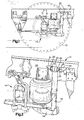
- the connection of the shock absorber 16 to the frame rail 10 includes a pair of integral brackets 20 in the embodiment of Figures 1,2 ,-4 and 5 and a single integral bracket in the embodiment of Figure 3 .
- a pair of spaced bracket apertures 24 have been formed by cutting the frame rail 10 as a step in forming the brackets 20, as depicted in Figure 4 .
- the brackets 20 are bent along junctures 25 between the cut out portions and the balance of the frame rail 10, Figure 5 .
- the brackets 20 are positioned in spaced parallel relationship.
- Each of the brackets 20 is in a respective imaginary, vertical plane normal to a vertical body portion 26 of the frame rail 10. As will be apparent from an examination of the drawings the vertical portion 26 is the body of a typical frame rail formed from an elongate channel.
- the fastener holes 30 are axially aligned.
- a fastener 28 extends through the holes 30 in the brackets 20.
- the fastener 28 also extends through a top mounting portion 32 of the shock absorber 16 to secure the shock absorber to the frame 10.
- a single bracket 33 is disposed in a generally horizontal plane when the vehicle is in use.
- a bracket aperture 34 has been formed in the vertical portion 26.
- the single bracket 33 has been formed by bending a cut out portion from the plane of the vertical portion 26 along a juncture 35 of the single bracket 33 with the vertical portion 26 at the base of the aperture 34.
- the single bracket 33 is disposed in a generally horizontal plane normal to the vertical portion 26 when in use.
- a shock fastener 36 projects through a fastener hole in the single bracket 33 to secure the shock absorber 16' to the single bracket.
Landscapes
- Engineering & Computer Science (AREA)
- Mechanical Engineering (AREA)
- Body Structure For Vehicles (AREA)
Claims (12)
- Châssis pour un véhicule routier, comprenant :a) une paire de longerons (10) allongés, positionnés longitudinalement dans un véhicule lorsqu'il est en fonctionnement ;b) une pluralité de traverses interposées entre les longerons (10) et reliées à ceux-ci, et qui maintiennent les longerons (10) selon une relation espacée prédéterminée,c) au moins un des longerons (10) comprenant un support (20, 33) formé d'un seul tenant et faisant saillie latéralement depuis ledit au moins un longeron (10) ;d) le support (20, 33) étant adjacent à une ouverture de longeron (24, 34) résultant de la découpe du au moins un longeron (10) pour délimiter le support (20, 33) et, après cette découpe, du pliage du support (20, 33) pour le faire sortir du plan auquel appartient le au moins un longeron (10) ; et,e) le support comprenant un trou (30) de support traversant pour la réception d'une attache (28, 36) destinée à relier un composant de véhicule (16, 16') grâce au passage d'une attache (28, 36) à travers ledit trou traversant (30).
- Châssis selon la revendication 1, dans lequel au moins un support (20, 33) est formé dans chaque longeron (10).
- Procédé de formage d'un support (20, 33) dans un châssis de véhicule, comprenant les étapes consistant à :a) découper un corps (26) d'un longeron (10) pour former les côtés d'une partie découpée de support tout en laissant la partie découpée reliée au corps (26) ; et,b) plier la partie découpée le long du raccordement de la partie au corps (26) pour faire en sorte que cette partie soit un support intégré (20, 33) faisant saillie latéralement depuis le corps (26), et former un trou (24, 34) dans la partie pour raccorder un composant de véhicule (16, 16') au support (10, 33) grâce au passage d'une attache (28, 36) à travers le trou (30) présent dans le support (20, 33).
- Procédé selon la revendication 3, dans lequel le trou (24, 34) est formé par un poinçon.
- Procédé selon la revendication 4, dans lequel la partie découpée est formée par estampage.
- Procédé selon la revendication 3, dans lequel la partie découpée est formée par estampage.
- Châssis de véhicule possédant un support (20, 33) formé par le procédé selon la revendication 3.
- Châssis de véhicule possédant un support (20, 33) formé par le procédé selon la revendication 5.
- Véhicule routier, choisi parmi un camion ou un tracteur, comprenant un châssis selon la revendication 1 ou 2 et,f) un composant de véhicule (16, 16') relié au support (10, 33) grâce au passage d'une attache (28, 36) à travers un trou (30) présent dans le support (20, 33).
- Véhicule selon la revendication 9, dans lequel il existe au moins un support (20, 33) dans chaque longeron (10).
- Véhicule selon la revendication 9, dans lequel ledit composant (16, 16') est un pare-chocs.
- Procédé selon la revendication 3, dans lequel le longeron (10) est un profilé en U.
Applications Claiming Priority (3)
| Application Number | Priority Date | Filing Date | Title |
|---|---|---|---|
| US935042 | 2001-08-22 | ||
| US09/935,042 US6709014B2 (en) | 2001-08-22 | 2001-08-22 | Heavy duty vehicle frame |
| PCT/US2002/026244 WO2003018360A2 (fr) | 2001-08-22 | 2002-08-16 | Chassis pour vehicule lourd |
Publications (3)
| Publication Number | Publication Date |
|---|---|
| EP1420996A2 EP1420996A2 (fr) | 2004-05-26 |
| EP1420996A4 EP1420996A4 (fr) | 2006-08-30 |
| EP1420996B1 true EP1420996B1 (fr) | 2010-11-24 |
Family
ID=25466506
Family Applications (1)
| Application Number | Title | Priority Date | Filing Date |
|---|---|---|---|
| EP02796389A Expired - Lifetime EP1420996B1 (fr) | 2001-08-22 | 2002-08-16 | Chassis pour vehicule lourd |
Country Status (6)
| Country | Link |
|---|---|
| US (1) | US6709014B2 (fr) |
| EP (1) | EP1420996B1 (fr) |
| AT (1) | ATE489276T1 (fr) |
| AU (1) | AU2002332570A1 (fr) |
| DE (1) | DE60238413D1 (fr) |
| WO (1) | WO2003018360A2 (fr) |
Families Citing this family (12)
| Publication number | Priority date | Publication date | Assignee | Title |
|---|---|---|---|---|
| US6637809B1 (en) * | 2002-12-12 | 2003-10-28 | International Truck Intellectual Property Company, Llc. | Vehicle with novel frame rails |
| US7635750B2 (en) * | 2003-09-05 | 2009-12-22 | Sloan-Kettering Institute For Cancer Research | Method for preparing polyfunctionalized peptides and/or proteins via native chemical ligation |
| GB0523451D0 (en) * | 2005-11-18 | 2005-12-28 | Detroit Steel Products Co Inc | A vehicle suspension system |
| GB0619981D0 (en) * | 2006-10-10 | 2006-11-15 | Meritor Heavy Vehicle Sys Ltd | Suspension sub-assembly |
| US8235422B2 (en) * | 2007-03-22 | 2012-08-07 | Hendrickson Usa, L.L.C. | Heavy-duty vehicle frame |
| US20090014993A1 (en) * | 2007-06-25 | 2009-01-15 | Mark Tope | Weight distributed low impact vehicle system capable of remote area access |
| DE102011086517A1 (de) * | 2011-11-17 | 2013-05-23 | Zf Friedrichshafen Ag | Starrachse mit Luftfederung |
| US11104389B2 (en) * | 2018-03-31 | 2021-08-31 | Jeffrey William Ash | Clamping system |
| US20190337347A1 (en) * | 2018-05-04 | 2019-11-07 | Hendrickson USA., L.L.C. | Suspension Travel Control System |
| US11407270B2 (en) * | 2019-04-15 | 2022-08-09 | Rv Ride Control Llc | Adjustable spring mounting assembly for vehicle |
| CN110539601B (zh) * | 2019-08-14 | 2021-02-26 | 东风商用车有限公司 | 一种不匹配推力杆的复合式空气悬架系统 |
| US12187092B2 (en) | 2022-08-11 | 2025-01-07 | Rv Ride Control, Llc | Tandem axle suspension system with keeper having sliding slipper blocks |
Family Cites Families (27)
| Publication number | Priority date | Publication date | Assignee | Title |
|---|---|---|---|---|
| US2154154A (en) * | 1936-06-29 | 1939-04-11 | Midland Steel Prod Co | Motor vehicle frame |
| US3994055A (en) * | 1973-03-15 | 1976-11-30 | Zmc, Inc. | Method of preparing rain gutters for connection thereto of downspouts |
| US3934895A (en) * | 1974-11-20 | 1976-01-27 | Fox George G | Bowling bag cart |
| US4162090A (en) | 1978-03-06 | 1979-07-24 | Fruehauf Corporation | Vehicle axle suspension assembly |
| DE7829589U1 (de) * | 1978-10-04 | 1979-02-01 | Westfalia-Werke Franz Knoebel & Soehne Kg, 4832 Rheda-Wiedenbrueck | Aufhängung für die Gabelenden eines Längslenkers |
| US4273357A (en) * | 1979-02-21 | 1981-06-16 | Sheller-Globe Corporation | Vehicle suspension system |
| US4465299A (en) | 1982-11-30 | 1984-08-14 | Paccar Inc. | Vehicle suspension with load-controlled damping and load-controlled damper |
| US4828232A (en) | 1983-11-14 | 1989-05-09 | General Motors Corporation | Vehicle air suspension strut with compliant cover plate assembly |
| US5046752A (en) | 1988-03-31 | 1991-09-10 | Paccar Inc. | Axle suspension system |
| US4923210A (en) | 1989-03-28 | 1990-05-08 | Heider Merle J | Suspension and leveling system for a vehicle |
| US4995636A (en) | 1989-05-26 | 1991-02-26 | Mor/Ryde, Inc. | Trailing arm modular axle suspension unit |
| US5004369A (en) * | 1989-06-23 | 1991-04-02 | United Steel Products Co. | Slope and skew hanger |
| US5039124A (en) | 1989-11-06 | 1991-08-13 | Computer Design Chassis, Inc. | Motor vehicle frame and suspension assembly |
| US5058916A (en) | 1990-06-18 | 1991-10-22 | Lear Siegler Truck Products Corp. | Apparatus for providing additional lift in a retractable suspension |
| US5037126A (en) * | 1990-09-07 | 1991-08-06 | The Boler Company | Lightweight beam suspension system |
| AU666572B2 (en) | 1992-10-19 | 1996-02-15 | Hendrickson International Corporation | Axle suspension systems |
| US5393096A (en) | 1993-03-02 | 1995-02-28 | Nai Neway, Inc. | Suspension frame bracket |
| US5346247A (en) | 1993-05-14 | 1994-09-13 | Reyco Industries, Inc. | Truck air ride suspension |
| US5605364A (en) * | 1995-07-11 | 1997-02-25 | Shelledy; Jack R. | Doorway security device and method of using same |
| US5785345A (en) | 1995-10-16 | 1998-07-28 | The Boler Company | Means for and method of controlling frame rise in vehicle suspensions |
| US5893435A (en) | 1995-12-20 | 1999-04-13 | Fichtel & Sachs Ag | Vibration damper for a motor vehicle, the vibration damper having a decompression stop boundary bracket |
| US5649719A (en) | 1996-02-23 | 1997-07-22 | The Boler Company. | Linkage suspension system |
| US5924712A (en) | 1996-05-30 | 1999-07-20 | Neway Anchorlok International, Inc. | Dual trailing arm vehicle suspension |
| US6056305A (en) | 1997-11-03 | 2000-05-02 | Pribyl; Myron | Steering axle suspension system |
| KR100293672B1 (ko) * | 1997-11-21 | 2001-07-12 | 이계안 | 자동차의현가장치 |
| DE19962406A1 (de) * | 1999-12-22 | 2001-07-19 | Zf Lemfoerder Metallwaren Ag | Achsaufhängung für Starrachsen von Fahrzeugen |
| US6434907B1 (en) * | 2000-03-22 | 2002-08-20 | Dana Corporation | Closed channel structural member having internal reinforcement for vehicle body and frame assembly |
-
2001
- 2001-08-22 US US09/935,042 patent/US6709014B2/en not_active Expired - Fee Related
-
2002
- 2002-08-16 EP EP02796389A patent/EP1420996B1/fr not_active Expired - Lifetime
- 2002-08-16 WO PCT/US2002/026244 patent/WO2003018360A2/fr not_active Ceased
- 2002-08-16 DE DE60238413T patent/DE60238413D1/de not_active Expired - Lifetime
- 2002-08-16 AT AT02796389T patent/ATE489276T1/de not_active IP Right Cessation
- 2002-08-16 AU AU2002332570A patent/AU2002332570A1/en not_active Abandoned
Also Published As
| Publication number | Publication date |
|---|---|
| WO2003018360A2 (fr) | 2003-03-06 |
| US20030038471A1 (en) | 2003-02-27 |
| US6709014B2 (en) | 2004-03-23 |
| ATE489276T1 (de) | 2010-12-15 |
| DE60238413D1 (de) | 2011-01-05 |
| EP1420996A4 (fr) | 2006-08-30 |
| EP1420996A2 (fr) | 2004-05-26 |
| WO2003018360A3 (fr) | 2003-10-09 |
| AU2002332570A1 (en) | 2003-03-10 |
Similar Documents
| Publication | Publication Date | Title |
|---|---|---|
| US6434907B1 (en) | Closed channel structural member having internal reinforcement for vehicle body and frame assembly | |
| US6412818B1 (en) | Vehicle body and frame assembly and method of manufacturing same | |
| CA2470625C (fr) | Ensemble calandre avec panneau d'integration de composants | |
| CA2466241A1 (fr) | Soubassement modulaire pour vehicule moteur | |
| US6709014B2 (en) | Heavy duty vehicle frame | |
| US20080115363A1 (en) | Cast aluminum node for connecting vehicle frame members and method of manufacturing same | |
| US20030214155A1 (en) | Bi-metallic structural component for vehicle frame assembly | |
| US6769178B1 (en) | Method of manufacturing a vehicle frame assembly including hydroformed side rails having integrally formed mounting areas | |
| JP2008056230A (ja) | ハンガービームアセンブリ | |
| CA2520296C (fr) | Renfort de portiere a resistance elevee et a profil bas pour vehicule | |
| US6435297B1 (en) | Vehicle component mounting assembly | |
| US6439608B1 (en) | Bracket and side rail structure for supporting a steering gear on a vehicle frame assembly | |
| US6681488B2 (en) | Method of manufacturing a vehicle body and frame assembly | |
| US7032958B2 (en) | Body and frame assembly for a vehicle and method of assembling a vehicle | |
| US6513242B1 (en) | Method of manufacturing a vehicle body and frame assembly including hydroformed side rails | |
| US5700033A (en) | Removable cross member for vehicle frame | |
| US20070126198A1 (en) | Slotted axle assembly | |
| DE102007026702A1 (de) | Achskomponente und Verfahren zur Herstellung einer Achskomponente | |
| EP2774808B1 (fr) | Structure d'attachement d'élément de saisie d'assistance | |
| US7614151B2 (en) | Method of securing a bracket to a frame assembly | |
| JP4133723B2 (ja) | 自動車の前部車体構造 | |
| JP4398841B2 (ja) | シャシフレーム構造 | |
| US7334308B1 (en) | Method of securing a body mount support bracket on a vehicle body and frame assembly | |
| JPH11148529A (ja) | ナックルブラケット | |
| JP2003300481A (ja) | 車体構造 |
Legal Events
| Date | Code | Title | Description |
|---|---|---|---|
| PUAI | Public reference made under article 153(3) epc to a published international application that has entered the european phase |
Free format text: ORIGINAL CODE: 0009012 |
|
| AK | Designated contracting states |
Kind code of ref document: A2 Designated state(s): AT BE BG CH CY CZ DE DK EE ES FI FR GB GR IE IT LI LU MC NL PT SE SK TR |
|
| AX | Request for extension of the european patent |
Extension state: AL LT LV MK RO SI |
|
| 17P | Request for examination filed |
Effective date: 20040413 |
|
| RIC1 | Information provided on ipc code assigned before grant |
Ipc: B60G 13/00 20060101ALI20060720BHEP Ipc: B62D 21/02 20060101AFI20040213BHEP |
|
| A4 | Supplementary search report drawn up and despatched |
Effective date: 20060727 |
|
| 17Q | First examination report despatched |
Effective date: 20080611 |
|
| GRAP | Despatch of communication of intention to grant a patent |
Free format text: ORIGINAL CODE: EPIDOSNIGR1 |
|
| GRAS | Grant fee paid |
Free format text: ORIGINAL CODE: EPIDOSNIGR3 |
|
| GRAA | (expected) grant |
Free format text: ORIGINAL CODE: 0009210 |
|
| AK | Designated contracting states |
Kind code of ref document: B1 Designated state(s): AT BE BG CH CY CZ DE DK EE ES FI FR GB GR IE IT LI LU MC NL PT SE SK TR |
|
| REG | Reference to a national code |
Ref country code: GB Ref legal event code: FG4D |
|
| REG | Reference to a national code |
Ref country code: CH Ref legal event code: EP |
|
| REG | Reference to a national code |
Ref country code: IE Ref legal event code: FG4D |
|
| REF | Corresponds to: |
Ref document number: 60238413 Country of ref document: DE Date of ref document: 20110105 Kind code of ref document: P |
|
| REG | Reference to a national code |
Ref country code: NL Ref legal event code: VDEP Effective date: 20101124 |
|
| PG25 | Lapsed in a contracting state [announced via postgrant information from national office to epo] |
Ref country code: AT Free format text: LAPSE BECAUSE OF FAILURE TO SUBMIT A TRANSLATION OF THE DESCRIPTION OR TO PAY THE FEE WITHIN THE PRESCRIBED TIME-LIMIT Effective date: 20101124 Ref country code: BG Free format text: LAPSE BECAUSE OF FAILURE TO SUBMIT A TRANSLATION OF THE DESCRIPTION OR TO PAY THE FEE WITHIN THE PRESCRIBED TIME-LIMIT Effective date: 20110224 Ref country code: CY Free format text: LAPSE BECAUSE OF FAILURE TO SUBMIT A TRANSLATION OF THE DESCRIPTION OR TO PAY THE FEE WITHIN THE PRESCRIBED TIME-LIMIT Effective date: 20101124 Ref country code: SE Free format text: LAPSE BECAUSE OF FAILURE TO SUBMIT A TRANSLATION OF THE DESCRIPTION OR TO PAY THE FEE WITHIN THE PRESCRIBED TIME-LIMIT Effective date: 20101124 Ref country code: PT Free format text: LAPSE BECAUSE OF FAILURE TO SUBMIT A TRANSLATION OF THE DESCRIPTION OR TO PAY THE FEE WITHIN THE PRESCRIBED TIME-LIMIT Effective date: 20110324 Ref country code: FI Free format text: LAPSE BECAUSE OF FAILURE TO SUBMIT A TRANSLATION OF THE DESCRIPTION OR TO PAY THE FEE WITHIN THE PRESCRIBED TIME-LIMIT Effective date: 20101124 Ref country code: NL Free format text: LAPSE BECAUSE OF FAILURE TO SUBMIT A TRANSLATION OF THE DESCRIPTION OR TO PAY THE FEE WITHIN THE PRESCRIBED TIME-LIMIT Effective date: 20101124 |
|
| PG25 | Lapsed in a contracting state [announced via postgrant information from national office to epo] |
Ref country code: GR Free format text: LAPSE BECAUSE OF FAILURE TO SUBMIT A TRANSLATION OF THE DESCRIPTION OR TO PAY THE FEE WITHIN THE PRESCRIBED TIME-LIMIT Effective date: 20110225 |
|
| PG25 | Lapsed in a contracting state [announced via postgrant information from national office to epo] |
Ref country code: BE Free format text: LAPSE BECAUSE OF FAILURE TO SUBMIT A TRANSLATION OF THE DESCRIPTION OR TO PAY THE FEE WITHIN THE PRESCRIBED TIME-LIMIT Effective date: 20101124 Ref country code: EE Free format text: LAPSE BECAUSE OF FAILURE TO SUBMIT A TRANSLATION OF THE DESCRIPTION OR TO PAY THE FEE WITHIN THE PRESCRIBED TIME-LIMIT Effective date: 20101124 Ref country code: CZ Free format text: LAPSE BECAUSE OF FAILURE TO SUBMIT A TRANSLATION OF THE DESCRIPTION OR TO PAY THE FEE WITHIN THE PRESCRIBED TIME-LIMIT Effective date: 20101124 Ref country code: ES Free format text: LAPSE BECAUSE OF FAILURE TO SUBMIT A TRANSLATION OF THE DESCRIPTION OR TO PAY THE FEE WITHIN THE PRESCRIBED TIME-LIMIT Effective date: 20110307 |
|
| PG25 | Lapsed in a contracting state [announced via postgrant information from national office to epo] |
Ref country code: DK Free format text: LAPSE BECAUSE OF FAILURE TO SUBMIT A TRANSLATION OF THE DESCRIPTION OR TO PAY THE FEE WITHIN THE PRESCRIBED TIME-LIMIT Effective date: 20101124 Ref country code: SK Free format text: LAPSE BECAUSE OF FAILURE TO SUBMIT A TRANSLATION OF THE DESCRIPTION OR TO PAY THE FEE WITHIN THE PRESCRIBED TIME-LIMIT Effective date: 20101124 |
|
| PLBE | No opposition filed within time limit |
Free format text: ORIGINAL CODE: 0009261 |
|
| STAA | Information on the status of an ep patent application or granted ep patent |
Free format text: STATUS: NO OPPOSITION FILED WITHIN TIME LIMIT |
|
| 26N | No opposition filed |
Effective date: 20110825 |
|
| REG | Reference to a national code |
Ref country code: DE Ref legal event code: R097 Ref document number: 60238413 Country of ref document: DE Effective date: 20110825 |
|
| PG25 | Lapsed in a contracting state [announced via postgrant information from national office to epo] |
Ref country code: IT Free format text: LAPSE BECAUSE OF FAILURE TO SUBMIT A TRANSLATION OF THE DESCRIPTION OR TO PAY THE FEE WITHIN THE PRESCRIBED TIME-LIMIT Effective date: 20101124 |
|
| PG25 | Lapsed in a contracting state [announced via postgrant information from national office to epo] |
Ref country code: MC Free format text: LAPSE BECAUSE OF NON-PAYMENT OF DUE FEES Effective date: 20110831 |
|
| REG | Reference to a national code |
Ref country code: CH Ref legal event code: PL |
|
| GBPC | Gb: european patent ceased through non-payment of renewal fee |
Effective date: 20110816 |
|
| PG25 | Lapsed in a contracting state [announced via postgrant information from national office to epo] |
Ref country code: CH Free format text: LAPSE BECAUSE OF NON-PAYMENT OF DUE FEES Effective date: 20110831 Ref country code: LI Free format text: LAPSE BECAUSE OF NON-PAYMENT OF DUE FEES Effective date: 20110831 |
|
| REG | Reference to a national code |
Ref country code: FR Ref legal event code: ST Effective date: 20120430 |
|
| REG | Reference to a national code |
Ref country code: IE Ref legal event code: MM4A |
|
| REG | Reference to a national code |
Ref country code: DE Ref legal event code: R119 Ref document number: 60238413 Country of ref document: DE Effective date: 20120301 |
|
| PG25 | Lapsed in a contracting state [announced via postgrant information from national office to epo] |
Ref country code: IE Free format text: LAPSE BECAUSE OF NON-PAYMENT OF DUE FEES Effective date: 20110816 |
|
| PG25 | Lapsed in a contracting state [announced via postgrant information from national office to epo] |
Ref country code: FR Free format text: LAPSE BECAUSE OF NON-PAYMENT OF DUE FEES Effective date: 20110831 Ref country code: GB Free format text: LAPSE BECAUSE OF NON-PAYMENT OF DUE FEES Effective date: 20110816 |
|
| PG25 | Lapsed in a contracting state [announced via postgrant information from national office to epo] |
Ref country code: LU Free format text: LAPSE BECAUSE OF NON-PAYMENT OF DUE FEES Effective date: 20110816 |
|
| PG25 | Lapsed in a contracting state [announced via postgrant information from national office to epo] |
Ref country code: DE Free format text: LAPSE BECAUSE OF NON-PAYMENT OF DUE FEES Effective date: 20120301 |
|
| PG25 | Lapsed in a contracting state [announced via postgrant information from national office to epo] |
Ref country code: TR Free format text: LAPSE BECAUSE OF FAILURE TO SUBMIT A TRANSLATION OF THE DESCRIPTION OR TO PAY THE FEE WITHIN THE PRESCRIBED TIME-LIMIT Effective date: 20101124 |