EP1421843A2 - Mähdrescher mit Strohhäcksler - Google Patents
Mähdrescher mit Strohhäcksler Download PDFInfo
- Publication number
- EP1421843A2 EP1421843A2 EP03103531A EP03103531A EP1421843A2 EP 1421843 A2 EP1421843 A2 EP 1421843A2 EP 03103531 A EP03103531 A EP 03103531A EP 03103531 A EP03103531 A EP 03103531A EP 1421843 A2 EP1421843 A2 EP 1421843A2
- Authority
- EP
- European Patent Office
- Prior art keywords
- straw
- combine harvester
- guide element
- chopper
- ejection
- Prior art date
- Legal status (The legal status is an assumption and is not a legal conclusion. Google has not performed a legal analysis and makes no representation as to the accuracy of the status listed.)
- Granted
Links
Images


Classifications
-
- A—HUMAN NECESSITIES
- A01—AGRICULTURE; FORESTRY; ANIMAL HUSBANDRY; HUNTING; TRAPPING; FISHING
- A01F—PROCESSING OF HARVESTED PRODUCE; HAY OR STRAW PRESSES; DEVICES FOR STORING AGRICULTURAL OR HORTICULTURAL PRODUCE
- A01F12/00—Parts or details of threshing apparatus
- A01F12/40—Arrangements of straw crushers or cutters
Definitions
- the invention relates to a combine harvester with an axial separator and one adjacent to the outlet of the axial separator, rotatably driven ejection drum, which is set up by the Axialabscheider ejected crop residues in a straw chopper to be conveyed, whereby between the outlet of the ejection drum and the Inlet of the straw chopper a straw guide is arranged.
- Such a combine harvester is known from DE 43 13 841 A.
- the ejection drum serves to remove the crop residue from a Wegzu busyn Axialabscheider and feed a straw chopper.
- an adjustable Strouleitorgan To improve the lateral distribution of crop residues between the outlet of the ejection drum and the inlet of the Straw chopper provided an adjustable Strouleitorgan.
- an adjustable Strouleitorgan at the embodiments of this document, which refers to a Combine harvesting with an axial separator is not Long straw storage operation provided.
- a straw shaker that does not use an ejection drum is, is a pivotally mounted at its lower end Intake plate provided, which in one position the straw in the Straw chopper and it in its other position in front of the Straw chopper dumps on the ground.
- Such a pull-in sheet on combine harvesters with Axialtrennvorraumen and their associated ejection drums not usable.
- the object underlying the invention is seen therein a combine harvester with an axial separator and an ejection drum to provide, in which an unproblematic switching between Langstrohablage- and Humblestratrieb is possible.
- the straw guide element can be inserted between the long straw storage position, in the crop residues usually before the Straw shredders are placed on the ground, and the chopper position be pivoted, in the crop residues the Straw chopper be supplied. It moves on one Circular path between the chaff and long straw storage position.
- the straw chopper can be fixed to the frame of the combine harvester be attached as moving between the Langstrohablage- and the Hiffselposition is unnecessary.
- the straw guide element is preferably pivotable about an axis, which is parallel to the axis of rotation of the ejection drum.
- An advantage lies in that thereby adapting to the outer circle the ejection drum is possible, in particular, when the pivot axis the straw guide element and the axis of rotation of the ejection drum coincide.
- the straw guiding element encloses the ejection drum preferably concentric. In the Position in which the straw guide element guides the crop residues, d. H. in long straw storage position and / or the chopping position is because of the lack of sharp deflections of the crop residue flow a low-friction guidance of crop residues possible.
- the pivotable straw guide element around a horizontal, transverse to the direction of travel of Combine rotating axis pivoting.
- the crop residues can thus more or less far back and up distracted and either in the straw chopper or on the ground be encouraged.
- the pivot axis of the Strohleitelements or the ejection drum but also in Extend direction of travel.
- the straw guide preferably covers in the Long straw storage position the inlet of the straw chopper off and on leaves him free in the chopping position.
- the straw is thus in the long straw storage position prevented from entering the straw chopper penetrate while in the chopping position without Impairment reaches the straw chopper.
- the Pivoting example such that the straw guide is pivoted up and back when it comes out of the long straw storage position is moved to the chopping position. It But would also be a reverse arrangement conceivable in which the Strohleitelement the crop flow in the chopping position after leads behind; then it will be backwards or forwards in the Long straw storage position pivots.
- Similar straw baffles can be downstream of the straw chopper and / or downstream of the spent in the straw storage Strohleitelements be arranged.
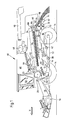
- Figure 1 shows a self-propelled combine harvester 10 with a Support frame 12, which is supported by wheels 14 on the ground and is moved away from them.
- the wheels 14 are not by means shown drive means rotated to the combine harvester 10 z. B. to move over a field to be harvested.
- a crop gathering device 16 connected to harvest crops from the field and it up and behind by an inclined conveyor 18 threshing and To supply separating agents.
- the threshing and separating agents comprise a transverse threshing drum 20 and one of these associated concave 21, which the harvested good first is supplied. But it is also conceivable, the threshing drum 20th to omit and to use an axial separator, the one Dreschabites and a separating section.
- Axialabscheider 24 It can be one single Axialabscheider or two (or more) side by side arranged Axialabscheider find use.
- a stripper roller 23 and a turning drum 22 lead together with a Feed housing the threshed crop from the threshing drum 20th and the concave 21 to the Axialabscheider 24.
- Of the Axialabscheider 24 is at its rear by a gear 80th driven. In the following, all directions, like front, back, above and below on the Forward direction V of the combine 10.
- Cereals and chaff which are deposited during the threshing process fall on at least one screw conveyor 30, the both feed to a preparation tray 33.
- Grain and chaff on the other hand, which emerge from the Axialabscheider 24 fall on one Shaking tray 32, which is for passing on the preparation tray 33 leads.
- the preparation soil 33 gives the grain and the chaff a screen box 34 on which a blower 36th is assigned to the deposition of the chaff from the grain support.
- Purified crop is made by means of a grain slug 38 fed to an elevator, not shown, which it transported into a grain tank 40.
- a reverse auger 42 gives ungagged ear parts by another, not shown Elevator back into the threshing process.
- the chaff can be at the Rear of the screening device by a rotating Chaff spreaders are ejected.
- the cleaned grain out the grain tank 40 can by a discharge system with transverse screws 44 and unloading conveyor 46.
- the systems mentioned are by means of an internal combustion engine 48 powered by an operator from a driver's cab 50 is controlled out.
- the different devices for threshing, conveying, cleaning and separating are located within the support frame 12.
- Axialabscheider 24 From Axialabscheider 24 are dried crop residues (Straw) through an outlet 64 at the bottom of the rear End of the rear closed Axialabscheiders 24 after ejected below. Due to the effect of centrifugal force and the Gravity the crop residues fall into a vertical Discharge chute bounded forward by a front wall 62 becomes. Below the outlet 64 is an ejection drum 66 arranged around the circumference driver 67 are distributed. To behind the ejection drum 66 from a rear wall 86th locked in. The ejection drum 66 is about its longitudinal axis, which extends transversely to the direction of travel, set in rotation, in Figure 1 in the counterclockwise direction.
- the Strohleitelement 68 may be about this axis between the in the Figures 1 and 3 shown Langstrohablageposition and in pivoted to Figures 2 and 4 shown Humbleselposition become.
- a per se known straw chopper 70th arranged around a horizontal, transverse to the direction of travel extending axis (in the figures counterclockwise) rotative is drivable. It includes a cylindrical body with pendulum pendulum attached chopper blades, which in the housing 72nd arranged stationary counter knives cooperate to the Harvesting crop residues and using straw trays 82 equipped straw distribution hood 74 about the cutting width of the combine 10 in the field.
- a part The housing 72 could also be above the straw chopper 70 from the front end of the straw distribution hood 70 circular arc until approximately to a point above the axis of rotation of the straw chopper 70th extend.
- the straw guide 68 is concave (circular arc) in itself curved and encloses the ejector drum 66 by one Angular range of about 45 ° concentric. It is at his in Transverse direction outer ends pivotally mounted on the support frame 12 of the Combine 10 hinged, as in Figures 3 and 4 shown.
- the straw guide 68 extends into the in the Figures 1 and 3 reproduced Langstrohablageposition of the front wall 62 to about the axis of rotation of the straw chopper 70. In this position, the straw guide 68 causes the threshed crop residue from the ejection drum 66 below an ejection hood 76 obliquely backwards and downwards become.
- the ejection hood 76 is like the straw dispenser hood 74 - Provided on their underside with straw guide plates 78 to the Width of the swath in which the crop residues are stored, too define.
- the straw guide element 68 In the chopping position, the straw guide element 68 is about the axis of rotation the ejection drum 66 (with respect to the figure 1 im Clockwise) pivoted backwards. This will between the front wall 62 and the front edge of the straw guiding element 68 an opening through which the crop remains in the Straw chopper 70 arrive.
- the straw guide 68 extends into this position, the rear wall 86 down and forward. In their area below the line at which the straw guide 68th comes to the concern when it is in the long straw storage position is located, the front wall 62 is also with Leitkufen 84th provided to the straw chopper 70 as evenly as possible to be able to feed.
- straw chopper 70 In the straw chopper 70 are the Chopped crop residues and slanted backwards and downwards ejected. Below the at the ejection of the straw chopper 70 arranged straw distribution hood 74 are straw baffles 82nd provided to specify the direction in which the crop remains be delivered to the bottom of the field.
- the straw guide element 68 can by hand by a mechanism or by suitable motors, preferably from the driver's cab 50 remotely controlled between the straw storage and the chopping position to be moved.
- the Leitkufen 84 at the lower part of the front wall 62 are on their front ends running transversely to the straw flow direction Axles 88 pivotally attached to the front wall 62, such as in particular with reference to the figure 4 can be seen. You can in manually adjusted and locked in a simple embodiment become. In another embodiment, they can by a common motor or more, each one or more Leitkufen 84 associated motors to be movable. The motors can manually controlled by the operator in the cab 50 become. But it can also be a sensor (or multiple sensors) be provided, which detects the width distribution of the straw and controls the engine or the motors, as in DE 102 15 026 A is described, the disclosure of which was incorporated by reference becomes.
- the Leitkufen 84 allow in Hburghnetrieb, an over the width uniform feed of the straw chopper 70 too produce.
- the straw guide plates 78 for long straw storage operation and the straw baffles 82 for the chopping operation can in a conventional manner at their front ends to the Be pivotally hinged and at its rear ends moved in the lateral direction to the swath width at Long straw storage or to define the width to which the chopped crop residues are distributed, as in Figures 5 and 6 for the straw guide plates 78 indicated.
- the adjustment can manually or by motor, in particular with a control by suitable sensors that automatically achieve the desired Ensure spread.
Landscapes
- Life Sciences & Earth Sciences (AREA)
- Environmental Sciences (AREA)
- Threshing Machine Elements (AREA)
- Outside Dividers And Delivering Mechanisms For Harvesters (AREA)
- Combines (AREA)
- Harvesting Machines For Specific Crops (AREA)
Abstract
Description
- Fig. 1
- einen Mähdrescher in Seitenansicht und schematischer Darstellung mit einem Axialabscheider und einer teilweise von einem Strohleitelement umschlossenen Auswurftrommel, der ein Strohhäcksler folgt, wobei sich das Strohleitelement in der Langstrohablageposition befindet,
- Fig. 2
- die Ansicht des Mähdreschers aus Figur 1 mit einem in die Häckselposition verbrachten Strohleitelement,
- Fig. 3
- eine perspektivische rückwärtige Ansicht der Auswurftrommel mit in die Langstrohablageposition verbrachtem Strohleitelement,
- Fig. 4
- eine perspektivische rückwärtige Ansicht der Auswurftrommel mit in die Häckselposition verbrachtem Strohleitelement,
- Fig. 5
- eine perspektivische Ansicht der Auswurftrommel und einer Auswurfhaube von unten, wobei das Strohleitelement aus Gründen der Übersichtlichkeit fortgelassen wurde, und
- Fig. 6
- eine Draufsicht auf die Axialabscheider des Mähdreschers und die Auswurfhaube.
Claims (11)
- Mähdrescher (10) mit einem Axialabscheider (24) und einer dem Auslass (64) des Axialabscheiders (24) benachbarten, rotativ antreibbaren Auswurftrommel (66), die eingerichtet ist, vom Axialabscheider (24) ausgeworfene Erntegutreste in einen Strohhäcksler (70) zu fördern, wobei zwischen der Auswurftrommel (66) und dem Strohhäcksler (70) ein Strohleitelement (68) angeordnet ist, dadurch gekennzeichnet, dass das Strohleitelement (68) um eine von ihm beabstandete Schwenkachse zwischen einer Häckselposition, in der die Pflanzenreste in den Strohhäcksler (74) gelangen, und einer Langstrohablageposition bewegbar ist, in der die Pflanzenreste ungehäckselt auf den Erdboden abgelegt werden.
- Mähdrescher nach Anspruch 1, dadurch gekennzeichnet, dass die Schwenkachse des Strohleitelements (68) parallel zur Drehachse der Auswurftrommel (66) verläuft.
- Mähdrescher nach Anspruch 1 oder 2, dadurch gekennzeichnet, dass das Strohleitelement (68) um die Drehachse der Auswurftrommel (66) schwenkbar ist.
- Mähdrescher (10) nach einem der Ansprüche 1 bis 3, dadurch gekennzeichnet, dass das Strohleitelement (68) einen Teilbereich der Auswurftrommel (66) konzentrisch umschließt.
- Mähdrescher (10) nach einem der Ansprüche 1 bis 4, dadurch gekennzeichnet, dass die Achse, um die das Strohleitelement (68) schwenkbar ist, horizontal und quer zur Fahrtrichtung des Mähdreschers (10) verläuft.
- Mähdrescher (10) nach einem der Ansprüche 1 bis 5, dadurch gekennzeichnet, dass das Strohleitelement (68) in der Langstrohablageposition den Einlass des Strohhäckslers (70) abdeckt und ihn in der Häckselposition freigibt.
- Mähdrescher (10) nach einem der Ansprüche 1 bis 6, dadurch gekennzeichnet, dass das Strohleitelement (68) aus der Häckselposition nach hinten und oben in die Langstrohablageposition verschwenkbar ist.
- Mähdrescher (10) nach einem der Ansprüche 1 bis 7, dadurch gekennzeichnet, dass stromauf des Strohhäckslers (70) verstellbare oder feste Leitkufen (84) angeordnet sind.
- Mähdrescher (10) nach einem der Ansprüche 1 bis 8, dadurch gekennzeichnet, dass stromab der Auswurftrommel (66) eine Auswurfhaube (76) folgt, die mit Strohleitblechen (78) besetzt ist, an denen das Stroh bei in die Langstrohablageposition verbrachtem Strohleitelement (68) entlangläuft.
- Mähdrescher (10) nach Anspruch 9, dadurch gekennzeichnet, dass die Strohleitbleche (68) verstellbar sind.
- Strohleiteinrichtung (68) eines Mähdreschers (10) nach einem der vorhergehenden Ansprüche.
Applications Claiming Priority (2)
| Application Number | Priority Date | Filing Date | Title |
|---|---|---|---|
| DE10249257 | 2002-10-23 | ||
| DE10249257A DE10249257A1 (de) | 2002-10-23 | 2002-10-23 | Mähdrescher mit Strohhäcksler |
Publications (3)
| Publication Number | Publication Date |
|---|---|
| EP1421843A2 true EP1421843A2 (de) | 2004-05-26 |
| EP1421843A3 EP1421843A3 (de) | 2007-10-03 |
| EP1421843B1 EP1421843B1 (de) | 2010-06-23 |
Family
ID=32114825
Family Applications (1)
| Application Number | Title | Priority Date | Filing Date |
|---|---|---|---|
| EP03103531A Expired - Lifetime EP1421843B1 (de) | 2002-10-23 | 2003-09-24 | Mähdrescher mit Strohhäcksler |
Country Status (7)
| Country | Link |
|---|---|
| US (1) | US6866580B2 (de) |
| EP (1) | EP1421843B1 (de) |
| AR (1) | AR041673A1 (de) |
| AT (1) | ATE471658T1 (de) |
| BR (1) | BR0304635A (de) |
| CA (1) | CA2445084C (de) |
| DE (2) | DE10249257A1 (de) |
Cited By (1)
| Publication number | Priority date | Publication date | Assignee | Title |
|---|---|---|---|---|
| US20250081888A1 (en) * | 2023-09-13 | 2025-03-13 | Cnh Industrial America Llc | Deflector door for accessing a sieve of a combine harvester having a seed mill |
Families Citing this family (29)
| Publication number | Priority date | Publication date | Assignee | Title |
|---|---|---|---|---|
| DE10256744A1 (de) | 2002-12-05 | 2004-06-17 | Deere & Company, Moline | Mähdrescher mit Strohhäcksler |
| US7306174B2 (en) * | 2004-03-04 | 2007-12-11 | Deere & Company | Broadcast width and location control for a combine spreader |
| DE102005019615A1 (de) * | 2005-04-28 | 2006-11-09 | Deere & Company, Moline | Mähdrescher |
| DE102006028706A1 (de) * | 2006-06-20 | 2008-02-21 | Claas Selbstfahrende Erntemaschinen Gmbh | Strohhäcksler für einen Mähdrescher |
| US20080092507A1 (en) * | 2006-10-18 | 2008-04-24 | Dragotec Usa, Inc. | Corn head with tension control for deck plates |
| DE102007005173B4 (de) | 2007-01-29 | 2014-02-27 | Claas Selbstfahrende Erntemaschinen Gmbh | Mähdrescher sowie Verfahren zum Häckseln von Stroh in einem Mähdrescher |
| BRPI0818304A2 (pt) * | 2007-11-01 | 2014-09-23 | Univ Iowa State Res Found Inc | Unidade de movimento de ar para melhoria de desempenho de transporte, separação ou de máquina de ceifar e debulhar de biomassa. |
| DE102009003123A1 (de) * | 2009-05-14 | 2010-11-18 | Deere & Company, Moline | Erntegutrestehäcksel und-verteilanordnung für einen Mähdrescher |
| US7717779B1 (en) * | 2009-08-26 | 2010-05-18 | Deere & Company | Combine with a conveyor switchable between swath deposit operation and chopper operation in different directions of rotation |
| US8585475B2 (en) * | 2011-04-19 | 2013-11-19 | Cnh America Llc | Crop residue distribution apparatus and system with cooperatively movable deflector door and spreader assembly |
| EP2833710B1 (de) * | 2012-03-26 | 2017-06-28 | CNH Industrial Belgium nv | Oszillierende pfanne eines mähdreschers mit einer flusssteuerungsleitschaufel |
| US9370141B2 (en) * | 2012-12-11 | 2016-06-21 | Cnh Industrial America Llc | Spreader system for an agricultural harvester |
| US10492369B2 (en) | 2015-07-14 | 2019-12-03 | Dean Mayerle | Weed seed destruction |
| AU2017228663B2 (en) * | 2015-07-14 | 2018-08-30 | Tritana Intellectual Property Ltd. | Weed seed destruction |
| ES2856970T3 (es) | 2015-07-14 | 2021-09-28 | Dean Mayerle | Destrucción de semillas de malas hierbas |
| BE1024322B1 (nl) * | 2016-06-28 | 2018-01-29 | Cnh Ind Belgium Nv | Ventilator in dorstrommel om blokkering van een strokap te vermijden |
| CN110198628B (zh) * | 2016-09-23 | 2023-10-27 | 种子终结者控股有限公司 | 一种多级锤磨机和包含其的残渣处理系统 |
| US10952374B2 (en) | 2017-05-01 | 2021-03-23 | Cnh Industrial America Llc | System and method for monitoring residue output from a harvester |
| US10537062B2 (en) | 2017-05-26 | 2020-01-21 | Cnh Industrial America Llc | Aerial vehicle systems and methods |
| US11832557B2 (en) * | 2018-04-11 | 2023-12-05 | Cnh Industrial America Llc | Rotational rotor discharge deflector |
| JP7155380B2 (ja) * | 2018-09-21 | 2022-10-18 | 株式会社クボタ | コンバイン |
| JP6980629B2 (ja) * | 2018-09-21 | 2021-12-15 | 株式会社クボタ | コンバイン |
| US12610886B2 (en) | 2019-03-14 | 2026-04-28 | Tritana Intellectual Property Ltd. | Weed seed destruction on a combine harvester including transferring grain from the grain loss sensor to the destructor |
| CA3222030C (en) | 2019-03-14 | 2026-01-13 | Tritana Intellectual Property Ltd. | Weed seed destruction |
| US20230337588A1 (en) | 2019-03-14 | 2023-10-26 | Tritana Intellectual Property Ltd. | Weed seed destruction |
| US12604812B2 (en) | 2019-03-14 | 2026-04-21 | Tritana Intellectual Property Ltd. | Weed seed destruction on a combine harvester including a moveable guide wall for the chaff and weed seeds from the sieve |
| AU2021235800B2 (en) | 2020-03-12 | 2024-06-13 | Tritana Intellectual Property Ltd. | Weed seed destruction |
| CA3241885A1 (en) | 2021-07-30 | 2023-02-02 | Tritana Intellectual Property Ltd. | Weed seed destruction |
| CN117529998A (zh) * | 2023-12-28 | 2024-02-09 | 德州凤麟农业服务有限公司 | 一种可应用于秸秆还田的小麦收割机 |
Citations (2)
| Publication number | Priority date | Publication date | Assignee | Title |
|---|---|---|---|---|
| US4056107A (en) | 1976-04-26 | 1977-11-01 | Sperry Rand Corporation | Crop residue deflector means |
| DE4313841A1 (de) | 1993-04-27 | 1994-11-03 | Biso Maschf Gmbh | Mähdrescher |
Family Cites Families (10)
| Publication number | Priority date | Publication date | Assignee | Title |
|---|---|---|---|---|
| US3670739A (en) * | 1971-07-14 | 1972-06-20 | Sperry Rand Corp | Axial flow combine with a rotary discharge and a straw chopper |
| US3712309A (en) * | 1972-03-29 | 1973-01-23 | Allis Chalmers | Straw chopper mounting for combine |
| DE2810176C2 (de) * | 1978-03-09 | 1979-12-13 | Gebr. Claas Maschinenfabrik Gmbh, 4834 Harsewinkel | Mähdrescher mit Anbauhäcksler |
| US4628946A (en) * | 1980-06-11 | 1986-12-16 | New Holland Inc. | Harvesting machine including chopper means |
| GB8305218D0 (en) * | 1983-02-25 | 1983-03-30 | Sperry Nv | Combine harvesters |
| DE3415708A1 (de) * | 1984-04-27 | 1985-10-31 | Biso Bitter Gmbh & Co Kg, 4520 Melle | Maehdrescher |
| US4669489A (en) * | 1985-12-02 | 1987-06-02 | Deere & Company | Straw chopper mounting for a combine |
| DE3735669A1 (de) * | 1987-10-22 | 1989-05-03 | Claas Ohg | Maehdrescher |
| DE3834102A1 (de) * | 1988-10-07 | 1990-04-12 | Claas Ohg | Maehdrescher |
| DE10219895A1 (de) * | 2002-05-03 | 2003-12-24 | Deere & Co | Mähdrescher mit Strohhäcksler |
-
2002
- 2002-10-23 DE DE10249257A patent/DE10249257A1/de not_active Withdrawn
-
2003
- 2003-09-24 EP EP03103531A patent/EP1421843B1/de not_active Expired - Lifetime
- 2003-09-24 DE DE50312827T patent/DE50312827D1/de not_active Expired - Lifetime
- 2003-09-24 AT AT03103531T patent/ATE471658T1/de not_active IP Right Cessation
- 2003-10-06 US US10/679,592 patent/US6866580B2/en not_active Expired - Lifetime
- 2003-10-14 CA CA002445084A patent/CA2445084C/en not_active Expired - Fee Related
- 2003-10-20 AR ARP030103816A patent/AR041673A1/es active IP Right Grant
- 2003-10-21 BR BR0304635-4A patent/BR0304635A/pt active Search and Examination
Patent Citations (2)
| Publication number | Priority date | Publication date | Assignee | Title |
|---|---|---|---|---|
| US4056107A (en) | 1976-04-26 | 1977-11-01 | Sperry Rand Corporation | Crop residue deflector means |
| DE4313841A1 (de) | 1993-04-27 | 1994-11-03 | Biso Maschf Gmbh | Mähdrescher |
Cited By (1)
| Publication number | Priority date | Publication date | Assignee | Title |
|---|---|---|---|---|
| US20250081888A1 (en) * | 2023-09-13 | 2025-03-13 | Cnh Industrial America Llc | Deflector door for accessing a sieve of a combine harvester having a seed mill |
Also Published As
| Publication number | Publication date |
|---|---|
| AR041673A1 (es) | 2005-05-26 |
| DE50312827D1 (de) | 2010-08-05 |
| BR0304635A (pt) | 2004-08-31 |
| EP1421843B1 (de) | 2010-06-23 |
| DE10249257A1 (de) | 2004-05-19 |
| CA2445084A1 (en) | 2004-04-23 |
| US20040132517A1 (en) | 2004-07-08 |
| ATE471658T1 (de) | 2010-07-15 |
| US6866580B2 (en) | 2005-03-15 |
| CA2445084C (en) | 2007-06-26 |
| EP1421843A3 (de) | 2007-10-03 |
Similar Documents
| Publication | Publication Date | Title |
|---|---|---|
| EP1421843B1 (de) | Mähdrescher mit Strohhäcksler | |
| EP1358789B1 (de) | Mähdrescher mit Strohhäcksler | |
| EP1442649B1 (de) | Mähdrescher mit Strohhäcksler | |
| EP1425956B1 (de) | Mähdrescher mit Strohhäcksler | |
| EP2175710B1 (de) | Mähdrescher mit einem zusätzlichen trommelförderer zur strohabförderung und einer einzigen klappe zum wechseln zwischen schwadablage- und häckselbetrieb | |
| EP2022310B1 (de) | Zwischen Breitverteil- und Auswurfkrümmerbetrieb umschaltbare Erntegutresteabgabeanordnung für einen Mähdrescher | |
| EP2250870B1 (de) | Erntegutrestehäcksel und -verteilanordnung für einen Mähdrescher | |
| EP1716736B1 (de) | Mähdrescher | |
| EP2250869B1 (de) | Erntegutrestehäcksel und -verteilanordnung für einen Mähdrescher | |
| DE10314081B4 (de) | Austrageinrichtung zum Austragen von Erntegut aus einer Erntemaschine | |
| DE102015220560B4 (de) | Mähdrescher mit einem zum Wechsel zwischen Schwadablagebetrieb und Häckselbetrieb in unterschiedlichen Drehrichtungen antreibbaren Strohhäcksler | |
| EP0095713B1 (de) | Erntemaschine mit einer Aufnahmevorrichtung | |
| EP1354508B1 (de) | Axialabscheider mit Leitschiene | |
| EP1579755B1 (de) | Strohleitrechen | |
| DE102008040137B4 (de) | Mähdrescher mit einem zwischen einer Schwadablageposition und einer Häckselposition bewegbaren Endlosförderer | |
| EP1842415B1 (de) | Leitblech für eine Verteilvorrichtung eines Strohhäckslers | |
| EP1530895B1 (de) | Mähdrescher mit Steinfalle | |
| EP1864566B1 (de) | Mähdrescher mit einer Körner abscheidenden Fördereinrichtung zwischen der Reinigungseinrichtung und einem Abgabeförderer für Spreu | |
| DE102008040125B4 (de) | Mähdrescher mit einem zusätzlichen Förderer zur Strohabförderung | |
| DE102008040119A1 (de) | Mähdrescher mit einem zum Wechsel zwischen Schwadablagebetrieb und Häckselbetrieb in unterschiedlichen Drehrichtungen antreibbaren Trommelförderer | |
| BE1023629B1 (de) | Erntegutresteverteileinrichtung für einen Mähdrescher | |
| DE102006042970A1 (de) | Mähdrescher mit einem dem Strohhäcksler zugeordneten Schutzbügel und einem Strohleitrechen | |
| DE102005048052A1 (de) | Erntegutresteverteileinrichtung für einen Mähdrescher | |
| DE102008040116B4 (de) | Mähdrescher mit einem Endlosförderer und einem zwischen einer Schwadablageposition und einer Häckselposition bewegbaren Leitblech | |
| DE10047464A1 (de) | Mähdrescher mit Axialabscheider und Auswurftrommel |
Legal Events
| Date | Code | Title | Description |
|---|---|---|---|
| PUAI | Public reference made under article 153(3) epc to a published international application that has entered the european phase |
Free format text: ORIGINAL CODE: 0009012 |
|
| AK | Designated contracting states |
Kind code of ref document: A2 Designated state(s): AT BE BG CH CY CZ DE DK EE ES FI FR GB GR HU IE IT LI LU MC NL PT RO SE SI SK TR |
|
| AX | Request for extension of the european patent |
Extension state: AL LT LV MK |
|
| PUAL | Search report despatched |
Free format text: ORIGINAL CODE: 0009013 |
|
| AK | Designated contracting states |
Kind code of ref document: A3 Designated state(s): AT BE BG CH CY CZ DE DK EE ES FI FR GB GR HU IE IT LI LU MC NL PT RO SE SI SK TR |
|
| AX | Request for extension of the european patent |
Extension state: AL LT LV MK |
|
| 17P | Request for examination filed |
Effective date: 20080403 |
|
| AKX | Designation fees paid |
Designated state(s): AT BE BG CH CY CZ DE DK EE ES FI FR GB GR HU IE IT LI LU MC NL PT RO SE SI SK TR |
|
| 17Q | First examination report despatched |
Effective date: 20081105 |
|
| GRAP | Despatch of communication of intention to grant a patent |
Free format text: ORIGINAL CODE: EPIDOSNIGR1 |
|
| GRAS | Grant fee paid |
Free format text: ORIGINAL CODE: EPIDOSNIGR3 |
|
| GRAA | (expected) grant |
Free format text: ORIGINAL CODE: 0009210 |
|
| AK | Designated contracting states |
Kind code of ref document: B1 Designated state(s): AT BE BG CH CY CZ DE DK EE ES FI FR GB GR HU IE IT LI LU MC NL PT RO SE SI SK TR |
|
| REG | Reference to a national code |
Ref country code: CH Ref legal event code: EP |
|
| REG | Reference to a national code |
Ref country code: IE Ref legal event code: FG4D Free format text: LANGUAGE OF EP DOCUMENT: GERMAN |
|
| REF | Corresponds to: |
Ref document number: 50312827 Country of ref document: DE Date of ref document: 20100805 Kind code of ref document: P |
|
| REG | Reference to a national code |
Ref country code: NL Ref legal event code: VDEP Effective date: 20100623 |
|
| PG25 | Lapsed in a contracting state [announced via postgrant information from national office to epo] |
Ref country code: SE Free format text: LAPSE BECAUSE OF FAILURE TO SUBMIT A TRANSLATION OF THE DESCRIPTION OR TO PAY THE FEE WITHIN THE PRESCRIBED TIME-LIMIT Effective date: 20100623 |
|
| PG25 | Lapsed in a contracting state [announced via postgrant information from national office to epo] |
Ref country code: FI Free format text: LAPSE BECAUSE OF FAILURE TO SUBMIT A TRANSLATION OF THE DESCRIPTION OR TO PAY THE FEE WITHIN THE PRESCRIBED TIME-LIMIT Effective date: 20100623 Ref country code: SI Free format text: LAPSE BECAUSE OF FAILURE TO SUBMIT A TRANSLATION OF THE DESCRIPTION OR TO PAY THE FEE WITHIN THE PRESCRIBED TIME-LIMIT Effective date: 20100623 |
|
| PG25 | Lapsed in a contracting state [announced via postgrant information from national office to epo] |
Ref country code: GR Free format text: LAPSE BECAUSE OF FAILURE TO SUBMIT A TRANSLATION OF THE DESCRIPTION OR TO PAY THE FEE WITHIN THE PRESCRIBED TIME-LIMIT Effective date: 20100924 |
|
| PG25 | Lapsed in a contracting state [announced via postgrant information from national office to epo] |
Ref country code: NL Free format text: LAPSE BECAUSE OF FAILURE TO SUBMIT A TRANSLATION OF THE DESCRIPTION OR TO PAY THE FEE WITHIN THE PRESCRIBED TIME-LIMIT Effective date: 20100623 Ref country code: EE Free format text: LAPSE BECAUSE OF FAILURE TO SUBMIT A TRANSLATION OF THE DESCRIPTION OR TO PAY THE FEE WITHIN THE PRESCRIBED TIME-LIMIT Effective date: 20100623 |
|
| REG | Reference to a national code |
Ref country code: IE Ref legal event code: FD4D |
|
| PG25 | Lapsed in a contracting state [announced via postgrant information from national office to epo] |
Ref country code: SK Free format text: LAPSE BECAUSE OF FAILURE TO SUBMIT A TRANSLATION OF THE DESCRIPTION OR TO PAY THE FEE WITHIN THE PRESCRIBED TIME-LIMIT Effective date: 20100623 Ref country code: RO Free format text: LAPSE BECAUSE OF FAILURE TO SUBMIT A TRANSLATION OF THE DESCRIPTION OR TO PAY THE FEE WITHIN THE PRESCRIBED TIME-LIMIT Effective date: 20100623 Ref country code: PT Free format text: LAPSE BECAUSE OF FAILURE TO SUBMIT A TRANSLATION OF THE DESCRIPTION OR TO PAY THE FEE WITHIN THE PRESCRIBED TIME-LIMIT Effective date: 20101025 Ref country code: DK Free format text: LAPSE BECAUSE OF NON-PAYMENT OF DUE FEES Effective date: 20100623 Ref country code: CZ Free format text: LAPSE BECAUSE OF FAILURE TO SUBMIT A TRANSLATION OF THE DESCRIPTION OR TO PAY THE FEE WITHIN THE PRESCRIBED TIME-LIMIT Effective date: 20100623 Ref country code: CY Free format text: LAPSE BECAUSE OF FAILURE TO SUBMIT A TRANSLATION OF THE DESCRIPTION OR TO PAY THE FEE WITHIN THE PRESCRIBED TIME-LIMIT Effective date: 20100623 |
|
| PG25 | Lapsed in a contracting state [announced via postgrant information from national office to epo] |
Ref country code: IE Free format text: LAPSE BECAUSE OF FAILURE TO SUBMIT A TRANSLATION OF THE DESCRIPTION OR TO PAY THE FEE WITHIN THE PRESCRIBED TIME-LIMIT Effective date: 20100623 Ref country code: MC Free format text: LAPSE BECAUSE OF NON-PAYMENT OF DUE FEES Effective date: 20100930 |
|
| PLBE | No opposition filed within time limit |
Free format text: ORIGINAL CODE: 0009261 |
|
| REG | Reference to a national code |
Ref country code: CH Ref legal event code: PL |
|
| STAA | Information on the status of an ep patent application or granted ep patent |
Free format text: STATUS: NO OPPOSITION FILED WITHIN TIME LIMIT |
|
| GBPC | Gb: european patent ceased through non-payment of renewal fee |
Effective date: 20100924 |
|
| 26N | No opposition filed |
Effective date: 20110324 |
|
| REG | Reference to a national code |
Ref country code: FR Ref legal event code: ST Effective date: 20110531 |
|
| REG | Reference to a national code |
Ref country code: DE Ref legal event code: R097 Ref document number: 50312827 Country of ref document: DE Effective date: 20110323 |
|
| PG25 | Lapsed in a contracting state [announced via postgrant information from national office to epo] |
Ref country code: FR Free format text: LAPSE BECAUSE OF NON-PAYMENT OF DUE FEES Effective date: 20100930 Ref country code: LI Free format text: LAPSE BECAUSE OF NON-PAYMENT OF DUE FEES Effective date: 20100930 Ref country code: CH Free format text: LAPSE BECAUSE OF NON-PAYMENT OF DUE FEES Effective date: 20100930 |
|
| PG25 | Lapsed in a contracting state [announced via postgrant information from national office to epo] |
Ref country code: GB Free format text: LAPSE BECAUSE OF NON-PAYMENT OF DUE FEES Effective date: 20100924 |
|
| PG25 | Lapsed in a contracting state [announced via postgrant information from national office to epo] |
Ref country code: AT Free format text: LAPSE BECAUSE OF NON-PAYMENT OF DUE FEES Effective date: 20100924 |
|
| PG25 | Lapsed in a contracting state [announced via postgrant information from national office to epo] |
Ref country code: LU Free format text: LAPSE BECAUSE OF NON-PAYMENT OF DUE FEES Effective date: 20100924 Ref country code: HU Free format text: LAPSE BECAUSE OF FAILURE TO SUBMIT A TRANSLATION OF THE DESCRIPTION OR TO PAY THE FEE WITHIN THE PRESCRIBED TIME-LIMIT Effective date: 20101224 Ref country code: BG Free format text: LAPSE BECAUSE OF FAILURE TO SUBMIT A TRANSLATION OF THE DESCRIPTION OR TO PAY THE FEE WITHIN THE PRESCRIBED TIME-LIMIT Effective date: 20100623 |
|
| PG25 | Lapsed in a contracting state [announced via postgrant information from national office to epo] |
Ref country code: TR Free format text: LAPSE BECAUSE OF FAILURE TO SUBMIT A TRANSLATION OF THE DESCRIPTION OR TO PAY THE FEE WITHIN THE PRESCRIBED TIME-LIMIT Effective date: 20100623 |
|
| PG25 | Lapsed in a contracting state [announced via postgrant information from national office to epo] |
Ref country code: BG Free format text: LAPSE BECAUSE OF FAILURE TO SUBMIT A TRANSLATION OF THE DESCRIPTION OR TO PAY THE FEE WITHIN THE PRESCRIBED TIME-LIMIT Effective date: 20100923 |
|
| PG25 | Lapsed in a contracting state [announced via postgrant information from national office to epo] |
Ref country code: ES Free format text: LAPSE BECAUSE OF FAILURE TO SUBMIT A TRANSLATION OF THE DESCRIPTION OR TO PAY THE FEE WITHIN THE PRESCRIBED TIME-LIMIT Effective date: 20101004 |
|
| PGFP | Annual fee paid to national office [announced via postgrant information from national office to epo] |
Ref country code: IT Payment date: 20140923 Year of fee payment: 12 |
|
| PG25 | Lapsed in a contracting state [announced via postgrant information from national office to epo] |
Ref country code: IT Free format text: LAPSE BECAUSE OF NON-PAYMENT OF DUE FEES Effective date: 20150924 |
|
| PGFP | Annual fee paid to national office [announced via postgrant information from national office to epo] |
Ref country code: BE Payment date: 20180927 Year of fee payment: 16 |
|
| REG | Reference to a national code |
Ref country code: BE Ref legal event code: MM Effective date: 20190930 |
|
| PG25 | Lapsed in a contracting state [announced via postgrant information from national office to epo] |
Ref country code: BE Free format text: LAPSE BECAUSE OF NON-PAYMENT OF DUE FEES Effective date: 20190930 |
|
| REG | Reference to a national code |
Ref country code: DE Ref legal event code: R084 Ref document number: 50312827 Country of ref document: DE |
|
| PGFP | Annual fee paid to national office [announced via postgrant information from national office to epo] |
Ref country code: DE Payment date: 20220819 Year of fee payment: 20 |
|
| REG | Reference to a national code |
Ref country code: DE Ref legal event code: R071 Ref document number: 50312827 Country of ref document: DE |