EP1421860A2 - System und Verfahren zur mikrobioziden Gasentwicklung - Google Patents
System und Verfahren zur mikrobioziden Gasentwicklung Download PDFInfo
- Publication number
- EP1421860A2 EP1421860A2 EP03254249A EP03254249A EP1421860A2 EP 1421860 A2 EP1421860 A2 EP 1421860A2 EP 03254249 A EP03254249 A EP 03254249A EP 03254249 A EP03254249 A EP 03254249A EP 1421860 A2 EP1421860 A2 EP 1421860A2
- Authority
- EP
- European Patent Office
- Prior art keywords
- microbiocidal agent
- liquid
- agent
- chamber
- microbiocidal
- Prior art date
- Legal status (The legal status is an assumption and is not a legal conclusion. Google has not performed a legal analysis and makes no representation as to the accuracy of the status listed.)
- Withdrawn
Links
- 230000003641 microbiacidal effect Effects 0.000 title claims abstract description 96
- 238000000034 method Methods 0.000 title claims abstract description 35
- 239000003795 chemical substances by application Substances 0.000 claims abstract description 94
- 239000007788 liquid Substances 0.000 claims abstract description 52
- 239000007789 gas Substances 0.000 claims abstract description 36
- JVTAAEKCZFNVCJ-UHFFFAOYSA-N lactic acid Chemical compound CC(O)C(O)=O JVTAAEKCZFNVCJ-UHFFFAOYSA-N 0.000 claims abstract description 24
- 239000012159 carrier gas Substances 0.000 claims abstract description 22
- 235000013305 food Nutrition 0.000 claims abstract description 18
- 239000004310 lactic acid Substances 0.000 claims abstract description 12
- 235000014655 lactic acid Nutrition 0.000 claims abstract description 12
- 239000012530 fluid Substances 0.000 claims description 21
- 238000010438 heat treatment Methods 0.000 claims description 16
- 238000004891 communication Methods 0.000 claims description 7
- 238000005202 decontamination Methods 0.000 claims description 2
- 230000003588 decontaminative effect Effects 0.000 claims description 2
- 230000000813 microbial effect Effects 0.000 claims description 2
- 230000008016 vaporization Effects 0.000 claims 1
- CURLTUGMZLYLDI-UHFFFAOYSA-N Carbon dioxide Chemical compound O=C=O CURLTUGMZLYLDI-UHFFFAOYSA-N 0.000 description 28
- 235000015173 baked goods and baking mixes Nutrition 0.000 description 18
- 229910002092 carbon dioxide Inorganic materials 0.000 description 14
- 239000001569 carbon dioxide Substances 0.000 description 13
- 239000003755 preservative agent Substances 0.000 description 13
- 239000000126 substance Substances 0.000 description 11
- 238000002156 mixing Methods 0.000 description 10
- 238000000889 atomisation Methods 0.000 description 7
- 230000002335 preservative effect Effects 0.000 description 7
- QTBSBXVTEAMEQO-UHFFFAOYSA-N Acetic acid Chemical compound CC(O)=O QTBSBXVTEAMEQO-UHFFFAOYSA-N 0.000 description 6
- 238000000926 separation method Methods 0.000 description 6
- 238000004806 packaging method and process Methods 0.000 description 5
- 230000002093 peripheral effect Effects 0.000 description 5
- 239000000203 mixture Substances 0.000 description 4
- 238000003860 storage Methods 0.000 description 4
- 238000010586 diagram Methods 0.000 description 3
- 238000004519 manufacturing process Methods 0.000 description 3
- 239000002253 acid Substances 0.000 description 2
- 230000000845 anti-microbial effect Effects 0.000 description 2
- 235000012791 bagels Nutrition 0.000 description 2
- 235000008429 bread Nutrition 0.000 description 2
- 235000014510 cooky Nutrition 0.000 description 2
- 238000001816 cooling Methods 0.000 description 2
- 235000012459 muffins Nutrition 0.000 description 2
- 239000000047 product Substances 0.000 description 2
- 241000894006 Bacteria Species 0.000 description 1
- 230000003466 anti-cipated effect Effects 0.000 description 1
- 238000013459 approach Methods 0.000 description 1
- 230000009286 beneficial effect Effects 0.000 description 1
- 239000007795 chemical reaction product Substances 0.000 description 1
- 230000000052 comparative effect Effects 0.000 description 1
- 238000010276 construction Methods 0.000 description 1
- 238000013461 design Methods 0.000 description 1
- 230000000694 effects Effects 0.000 description 1
- 239000002360 explosive Substances 0.000 description 1
- 231100001261 hazardous Toxicity 0.000 description 1
- 238000011065 in-situ storage Methods 0.000 description 1
- 238000009434 installation Methods 0.000 description 1
- 239000007791 liquid phase Substances 0.000 description 1
- 238000000465 moulding Methods 0.000 description 1
- 239000012071 phase Substances 0.000 description 1
- 238000002360 preparation method Methods 0.000 description 1
- 238000004321 preservation Methods 0.000 description 1
- 230000003134 recirculating effect Effects 0.000 description 1
- 238000011084 recovery Methods 0.000 description 1
- 238000012546 transfer Methods 0.000 description 1
- 239000006200 vaporizer Substances 0.000 description 1
- 239000003039 volatile agent Substances 0.000 description 1
Images


Classifications
-
- A—HUMAN NECESSITIES
- A01—AGRICULTURE; FORESTRY; ANIMAL HUSBANDRY; HUNTING; TRAPPING; FISHING
- A01N—PRESERVATION OF BODIES OF HUMANS OR ANIMALS OR PLANTS OR PARTS THEREOF; BIOCIDES, e.g. AS DISINFECTANTS, AS PESTICIDES OR AS HERBICIDES; PEST REPELLANTS OR ATTRACTANTS; PLANT GROWTH REGULATORS
- A01N25/00—Biocides, pest repellants or attractants, or plant growth regulators, characterised by their forms, or by their non-active ingredients or by their methods of application, e.g. seed treatment or sequential application; Substances for reducing the noxious effect of the active ingredients to organisms other than pests
- A01N25/18—Vapour or smoke emitting compositions with delayed or sustained release
Definitions
- the invention relates generally to the application of microbiocidal substances to products, particularly food products. More particularly, the invention relates to the generation and the use of microbiocidal agents without using a carrier gas for the treatment of food products
- baked goods e.g., muffins, crumpets, scones, bagels, cookies, breads, etc.
- baked goods can be placed in frozen or refrigerated storage, covered with anaerobic packaging, and/or supplemented by the addition of preservatives.
- preservatives can be added to either a batter or a mix from which the baked goods are prepared.
- the preservative can be applied to finished baked goods.
- preservatives can include a wide variety of substances (i.e., microbiocidal substances, antimicrobial substances, etc.) such as acetic acid, carbonic acid, mixtures thereof, and the like.
- volatile microbiocidal agents requires carrier gases to accommodate the volatile gases.
- the additional measures required during the design, fabrication, installation and use of equipment to be used with volatile gases and carrier gases can decrease the efficiency and increase the cost of a microbiocidal application process.
- explosion-proof components must be used, adding tremendous cost to the application system; specific procedures must be observed when storing the volatile gases, such storage oftentimes occurring off-site and out of the direct control of the supplier of the volatile gases; and detailed control and strict systems must be implemented to prevent leakage and prevent exposure to those in working with the volatile gases.
- the leakage of volatile gases can pose a significant risk to plant personnel.
- the use of a carrier gas requires that the microbiocidal substance be atomized. The atomized substance is then converted to vapor by mixing it with a super-heated carrier gas.
- the system requires the use of a metering system on the carrier gas, a metering pump for the microbiocidal acid, a heating system for the carrier gas, as well as an atomization system from the microbiocidal agent and a mixing vessel for the process.
- microbiocidal agent food treatment system that uses microbiocidal agents that are not mixed with super-heated carrier gases.
- an apparatus and method for providing treatment to a food product with a microbiocidal agent that is not combined with a carrier gas would be advantageous and therefore desirable, since such an apparatus and method would eliminate the need for the additional costs and equipment associated with the use of carrier gases in the treatment process.
- a method of generating a microbiocidal agent which includes providing a liquid microbiocidal agent, and heating the liquid microbiocidal agent to generate a gaseous microbiocidal agent.
- the heating step provides for the generation of the gaseous microbiocidal agent without a carrier gas.
- the invention provides a method according to any one of claims 1 to 9, and an apparatus according to any one of claims 10 to 17.
- a preservative e.g., a microbiocidal substance
- the invention can also be employed with, and has applicability to, many different application processes.
- an outline 2 is illustrated for preparation of commercial quantities of a food product, namely a baked good (e.g., muffin, crumpet, scone, bagel, cookie, bread, and the like).
- Batter is prepared and then poured into molds that are either carried on, or form a part of, a conveyor mechanism.
- the conveyor mechanism moves the batter through a baking zone in which the batter is fully baked.
- the baked good Upon leaving the baking zone, the baked good is de-molded, typically onto a second conveyor mechanism.
- the de-molding procedure typically deposits the baked goods upon the second conveyor mechanism such that the baked goods are arranged in an indexed array.
- the indexed array of baked goods are then conveyed through a cooling tunnel to bring the baked goods to a temperature appropriate for packaging (e.g., room temperature or slightly above).
- the baked goods will pass through a treatment apparatus.
- the baked goods Prior to encountering the treatment apparatus, the baked goods are assembled into batches. In batches, the baked goods are transported through the treatment apparatus where a treatment fluid containing a preservative is applied to an external surface of the baked goods.
- Typical preservatives can include a wide variety of substances (i.e., microbiocidal substances, antimicrobial substances, etc.). Preservatives have the ability to radically reduce the pH of food products and, as such, can eradicate and/or eliminate bacteria present within the food product.
- the treatment fluid can include a preservative or a mixture containing the preservative. For example, a vaporized mixture of carbon dioxide and an application agent can be employed as the treatment fluid.
- Figure 3 illustrates a treatment fluid generation apparatus that includes the use of a carrier gas and, unlike the present invention, generates a microbiocidal agent in the form of an atomised liquid. The description of Figure 3 is thus provided for comparative and explanatory purposes.
- tank 101 holds liquid carbon dioxide, typically at about three hundred (300) psig.
- Liquid carbon dioxide is transferred to vaporizer 102 and converted to a gas substantially free of any droplets.
- the gas is then passed through pressure reduction valve 103 and the pressure of the gas is reduced from three hundred (300) psig to one hundred (100) psig.
- the gaseous CO 2 is then transferred to heater 104 and heated to substantially the same temperature as the contents of mixing/separation chamber 123 (e.g., 140° F).
- Temperature control unit 126 coordinates the temperature of heater 104 and of chamber 123. From heater 104, the gaseous carbon dioxide at one hundred (100) psig is transferred to mass flow meter 105, which is controlled by flow control 106.
- flow control 106 allows carbon dioxide to move from mass flow meter 105 into pipe 108.
- Pipe 108 divides into pipes 109 and 110. While the amount of carbon dioxide each of pipes 109 and 110 will carry can vary to convenience, typically pipe 109 will carry about ten percent (10%) and pipe 110 will carry the remaining about ninety percent (90%) by weight of the carbon dioxide.
- the stream of carbon dioxide passing through in pipe 110 can also pass through control valve 111 before entering mixing antechamber 112.
- Liquid acid such as lactic acid
- lactic acid is removed from tank 113 through check valve 114 by the action of pump 115.
- the liquid lactic acid moves through line 116 and valve 117 into metering pump 107.
- atomization nozzle 120 is operational, then the liquid lactic acid is fed into the atomization nozzle where the liquid lactic acid is atomized with carbon dioxide delivered to the nozzle through line 109.
- atomization nozzle 120 is not operative, then the liquid lactic acid is returned to tank 113 by way of line 118 and check valve 119.
- Atomized lactic acid is transferred from atomization nozzle 120 into the upper section of mixing/separation chamber 123 in which it is vaporized by contact with carbon dioxide delivered from mixing antechamber 112 through orifice plate 121.
- the carbon dioxide delivered from line 110 into antechamber 112 passes through pressure reduction valve 111 in which the pressure of the carbon dioxide is reduced from one hundred (100) psig to about five (5) psig.
- the pressure of the atomized lactic acid as delivered to mixing/separation chamber 123 is also about five (5) psig.
- the temperature, pressure and volume of carbon dioxide introduced into the upper section of mixing/separation chamber 123 is sufficient such that the atomized lactic acid is essentially completely vaporized upon contact with it.
- Atomization nozzle 120 passes through antechamber 112 and orifice plate 121, and opens into the upper section of mixing/separation chamber 123.
- Atomization nozzle 120 can extend into the upper section of mixing/separation chamber 123 to any convenient length, but typically the end of the nozzle is flush with or extends only a short distance beyond orifice plate 121.
- the system 10 includes a tubular member 12 that acts as a heat exchanger.
- Tubular member 12 is a heat source or is associated with a heat source such that tubular member 12 is capable of being heated.
- a portion of the outside of tubular member 12 has been removed to facilitate understanding and explanation.
- a spiral tube-type heat exchanger is shown, other sizes and shapes may be employed.
- Insert 14 Disposed within tubular member 12 is insert 14.
- Insert 14 is preferably of a generally spiral configuration that causes liquid flowing into tubular member 12 to be disrupted and directed away from the center of tubular member 12, or to spirally disperse the liquid to the inner circumferential or the inner peripheral wall 22 of tubular member 12.
- insert 14 imparts a spiral fluid flow to the liquid microbiocidal agent as the liquid microbiocidal agent travels through the member 12.
- An insert of any shape that is capable of directing the liquid to inner peripheral wall 22 may be used.
- Tubular member 12 includes wall 16 that is heated, directly or indirectly, to facilitate heat transfer from the wall to the liquid travelling through tubular member 12.
- the general purpose of microbiocidal agent generation system 10 is to convert a liquid microbiocidal agent into a gaseous microbiocidal agent. Any suitable microbiocidal agent is contemplated, although lactic acid is preferred. Consistent with the purpose of converting the agent from a liquid phase to a gas phase, in operation liquid microbiocidal agent enters tubular member 12 at an inlet 20 in a direction indicated by arrow 18. Once introduced at inlet 20 of tubular member 12, insert 14 disrupts the flow of the liquid and directs the microbiocidal agent towards inner peripheral wall 22 of tubular member 12.
- tubular member 12 Because tubular member 12 is heated, contact between the wall 22 of the tubular member 12 and the liquid microbiocidal agent will cause the liquid microbiocidal agent to heat as it proceeds through tubular member 12. Upon sufficient heating of the liquid microbiocidal agent, a gaseous microbiocidal agent is generated that exits the member 12 at outlet 24 in the direction indicated by arrow 26. In this manner, the (gaseous) microbiocidal agent is generated for delivery without the use of a carrier gas.
- Figure 6 illustrates directing of the liquid microbiocidal agent 28 from a central region 30 of tubular member 12 in a radial fashion as indicated by, for example, direction arrows 32, such that the liquid microbiocidal agent 28 is dispersed against the inner peripheral wall 22 of tubular member 12 which is heated.
- liquid microbiocidal agent 28 is directed along the inner peripheral wall 22 of tubular member 12 such that heat energy from heated tubular member 12 is transferred to liquid microbiocidal agent 28.
- This process allows the heat energy from the heated tubular shell 12 to generate the gaseous microbiocidal agent without the use of a carrier gas for the liquid agent.
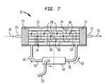
- System 50 provides the heat energy necessary to convert the liquid microbiocidal agent into a gaseous microbiocidal agent.
- System 50 includes a shell and tube type heat exchanger for the purpose of transferring heat energy from a recirculation gas to another fluid, in this case the microbiocidal agent, which may be used for microbial decontamination.
- System 50 is shown with a portion of the outer cover removed to facilitate understanding and explanation.
- System 50 includes a shell 52 and a plurality of tubes 54 disposed therein. Attached to and communicating with the interior of shell 52 is gas line 56 for recirculating gas through the system 50.
- the gas line 56 is in communication with a heater 58 to heat the gas traveling through gas line 56.
- the gas line 56 can be constructed to contain a fluid as well to provide heating of the tubes 54.
- the gas travels in a direction as indicated by arrow 60 through gas line 56, where it is heated by heater 58.
- the heated gas is introduced via gas line 56 in a direction indicated by arrow 62 into the interior 64 of shell 52.
- the heated gas then travels about a series of baffles 66 within the shell 52.
- Baffles 66 direct the gas in a substantially sinusoidal flow throughout the interior 64 of the shell 52, such that the gas will flow around and contact tubes 54, thereby transferring heat from the gas to the tubes 54.
- the gas travels in a sinusoidal flow substantially as indicated by arrows 68 to then exit the shell 52 into gas line 56 where the (now cooler) gas is recirculated to be exposed again to heater 58 for the process to repeat.
- liquid microbiocidal agent is introduced into heat exchanger inlet 69 in a direction indicated by arrow 70.
- the agent is then distributed to flow into the plurality of tubes 54.
- the heat from the gas is transferred to the tubes 54 and ultimately to the liquid microbiocidal agent, which is heated until it becomes a gaseous or vaporized microbiocidal agent.
- the heated (now gaseous) microbiocidal agent flows to outlet 72 as indicated by arrow 74.
- the gaseous microbiocidal agent exits system 50 for subsequent use, such as for treatment of food products.
- a fluid conduit 59 is in communication with the heater 58.
- the conduit 58 provides a fluid to be heated to the heater 58.
- the heater 58 can include a pump, such as a self-priming pump, to circulate the fluid through the conduit 56 and into the chamber 64 of the apparatus 50.
- the system 52 can include manifolds 71, 73 at both the inlet 69 and outlet 72, respectively, for the plurality of tubes 54. That is, the fluid introduced at the inlet 69 is guided into the manifold 71 which distributes the liquid in a substantially uniform manner to the plurality of tubes 54 so that all are filled with a substantially equal amount of agent to be heated and vaporized.
- the manifold 73 is disposed in the shell 52 to receive opposite ends of the plurality of tubes 54 to substantially uniformly direct the agent to the outlet 72 where it is discharged as a gaseous microbiocidal agent.
- An alternate embodiment calls for the plurality of tubes 54 being constructed and arranged as a single tube having one end in communication with the inlet 69 and an opposed end in communication with the outlet 72.
- An intermediate portion of the tube between the opposed ends is constructed and arranged in a sinusoidal manner to provide the agent introduced at the inlet 69 into the tube with a sufficient amount of residence time in the chamber 64 to be exposed to the heating effect of the fluid circulated through the line 56.
- FIG 8 illustrates a methodology shown generally at 200 associated with the generation of the gaseous or vapor microbiocidal agent in accordance with the present invention.
- the process starts 202 when it is desired to generate gaseous microbiocidal agent for application to, for example, food products.
- the first step is to introduce 204 liquid microbiocidal agent into a heat exchanger.
- a plurality of heat exchangers may be used, including those at Figures 4 and 7.
- the liquid microbiocidal agent is heated 206 by virtue of the operation of the heat exchanger.
- a gaseous microbiocidal agent is generated 208 by the heating of the liquid microbiocidal agent, and this generation of the gaseous agent occurs without a carrier gas. Therefore, it is not necessary to atomize the liquid microbiocidal agent prior to heating.
- the gaseous microbiocidal agent is generated within the heat exchanger at 210, it is necessary to recover the gaseous microbiocidal agent from the heat exchanger. Following this recovery, the gaseous microbiocidal agent is provided 212 to application equipment suitable for the intended end product to which the gaseous microbiocidal agent will be applied. It is anticipated that this process may be performed on a discrete or continuous basis and at some point in the process it is determined 214 whether more gaseous microbiocidal agent is needed. If so 216, liquid microbiocidal agent is again introduced 204 and the process continues. If more agent is not needed 218, the generation process reaches end 220.
Landscapes
- Life Sciences & Earth Sciences (AREA)
- General Health & Medical Sciences (AREA)
- Health & Medical Sciences (AREA)
- Toxicology (AREA)
- Pest Control & Pesticides (AREA)
- Plant Pathology (AREA)
- Agronomy & Crop Science (AREA)
- Engineering & Computer Science (AREA)
- Dentistry (AREA)
- Wood Science & Technology (AREA)
- Zoology (AREA)
- Environmental Sciences (AREA)
- Food Preservation Except Freezing, Refrigeration, And Drying (AREA)
- Agricultural Chemicals And Associated Chemicals (AREA)
Applications Claiming Priority (2)
| Application Number | Priority Date | Filing Date | Title |
|---|---|---|---|
| US199782 | 2002-07-22 | ||
| US10/199,782 US20040013694A1 (en) | 2002-07-22 | 2002-07-22 | System and method of microbiocidal gas generation |
Publications (2)
| Publication Number | Publication Date |
|---|---|
| EP1421860A2 true EP1421860A2 (de) | 2004-05-26 |
| EP1421860A3 EP1421860A3 (de) | 2004-12-15 |
Family
ID=30443406
Family Applications (1)
| Application Number | Title | Priority Date | Filing Date |
|---|---|---|---|
| EP03254249A Withdrawn EP1421860A3 (de) | 2002-07-22 | 2003-07-04 | System und Verfahren zur mikrobioziden Gasentwicklung |
Country Status (5)
| Country | Link |
|---|---|
| US (2) | US20040013694A1 (de) |
| EP (1) | EP1421860A3 (de) |
| AU (1) | AU2003213485B2 (de) |
| NZ (1) | NZ526991A (de) |
| PL (1) | PL361352A1 (de) |
Families Citing this family (6)
| Publication number | Priority date | Publication date | Assignee | Title |
|---|---|---|---|---|
| US7008658B2 (en) * | 2002-05-29 | 2006-03-07 | The Boc Group, Inc. | Apparatus and method for providing treatment to a continuous supply of food product by impingement |
| US8445419B2 (en) | 2005-07-25 | 2013-05-21 | Ecolab Usa Inc. | Antimicrobial compositions for use on food products |
| US20080274242A1 (en) * | 2006-07-21 | 2008-11-06 | Ecolab Inc. | Antimicrobial compositions and methods for treating packaged food products |
| DK1906743T3 (da) | 2005-07-25 | 2012-04-10 | Ecolab Inc | Antimikrobielle sammensætninger og fremgangsmåder til behandling af emballerede fødevareprodukter |
| JP4991719B2 (ja) * | 2005-07-25 | 2012-08-01 | イーコラブ インコーポレイティド | 抗菌組成物及び包装された食品の処理方法 |
| US10417612B2 (en) | 2013-12-04 | 2019-09-17 | Microsoft Technology Licensing, Llc | Enhanced service environments with user-specific working sets |
Citations (4)
| Publication number | Priority date | Publication date | Assignee | Title |
|---|---|---|---|---|
| EP0029640A1 (de) | 1979-11-23 | 1981-06-03 | PAULS & WHITES INTERNATIONAL (GB) LIMITED | Räuchergerät |
| DE19505239A1 (de) | 1995-02-16 | 1996-08-22 | Peter Pfizenmaier | Verfahren zum Verpacken eines Gutes |
| EP1247561A1 (de) | 2001-03-28 | 2002-10-09 | The Boc Group, Inc. | Vorrichtung und Verfahren zur Mischung eines Gases und einer Flüssigkeit |
| EP1369040A2 (de) | 2002-06-06 | 2003-12-10 | The Boc Group, Inc. | System und Verfahren zur Verwendung von nichtflüchtigen mikrobioziden Mitteln |
Family Cites Families (36)
| Publication number | Priority date | Publication date | Assignee | Title |
|---|---|---|---|---|
| US2523373A (en) * | 1946-05-10 | 1950-09-26 | Research Corp | Apparatus for air sterilization |
| US2665217A (en) * | 1952-09-05 | 1954-01-05 | Dow Chemical Co | Method for controlling mold and decay on fresh fruits and vegetables |
| US4145451A (en) * | 1977-04-27 | 1979-03-20 | Kraft, Inc. | Preservation of low acid food products in the absence of chemical preservatives |
| US4756919A (en) * | 1982-06-18 | 1988-07-12 | Thomas J. Lipton | Acid preservation systems for food products |
| US4550026A (en) * | 1983-02-15 | 1985-10-29 | Yosuke Akiba | Method for preserving food using a preservative gas atmosphere |
| US4830865A (en) * | 1986-12-15 | 1989-05-16 | Graham Corporation | Method for aseptically processing a food product |
| DE3618297A1 (de) * | 1986-05-30 | 1987-12-03 | Deutsche Ges Schaedlingsbek | Verfahren und vorrichtung zur herstellung eines entwesungsfluids |
| GB8616246D0 (en) * | 1986-07-03 | 1986-08-13 | Agricultural & Food Res | Improving shelf life of foodstuff |
| US4746524A (en) * | 1986-09-25 | 1988-05-24 | Curtice-Burns, Inc. | Microbiologically-resistant sauces and dressings and method for their preparation |
| US5173259A (en) * | 1988-04-27 | 1992-12-22 | Tetra Dev-Co | Sterilization method for a packing machine that uses liquid disinfectant |
| US5376333A (en) * | 1989-07-28 | 1994-12-27 | Alliedsignal, Inc. | Ethylene oxide-carrier gas compositions having improved flammability suppressant characteristics |
| SE463240B (sv) * | 1989-11-07 | 1990-10-29 | Tetra Pak Holdings & Finance | Saett att framstaella gasformigt, vaeteperoxidinnehaallande steriliseringsfluidum |
| US5258162A (en) * | 1989-11-07 | 1993-11-02 | Tetra Alfa Holdings S.A. | Method of producing a gaseous hydrogen peroxide-containing sterilization fluid |
| US5208057A (en) * | 1991-11-12 | 1993-05-04 | Rohm And Haas Company | Process for butchering and disinfecting fowl |
| US5229072A (en) * | 1992-02-03 | 1993-07-20 | Liquid Carbonic Inc. | Use of interhalogen compounds as a sterilizing agent |
| US5234703A (en) * | 1992-10-31 | 1993-08-10 | Guthery B Eugene | Disinfecting product and process |
| US5389390A (en) * | 1993-07-19 | 1995-02-14 | Kross; Robert D. | Process for removing bacteria from poultry and other meats |
| US5597530A (en) * | 1994-08-18 | 1997-01-28 | Abbott Laboratories | Process for prefilling and terminally sterilizing syringes |
| US5488156A (en) * | 1994-12-23 | 1996-01-30 | Uop | Preparation of a heat-stable lactic acid |
| US5872359A (en) * | 1995-07-27 | 1999-02-16 | American Sterilizer Company | Real-time monitor and control system and method for hydrogen peroxide vapor decontamination |
| US5730311A (en) * | 1995-11-13 | 1998-03-24 | Tenneco Packaging Inc. | Controlled atmosphere package |
| AUPN724095A0 (en) * | 1995-12-20 | 1996-01-18 | Inglis, Andrew | Method and apparatus for the application of volatile substances conveyed in carrier gas |
| US6157774A (en) * | 1997-05-16 | 2000-12-05 | Tokyo Electron Limited | Vapor generating method and apparatus using same |
| US5900266A (en) * | 1997-05-29 | 1999-05-04 | The Curators Of The University Of Missouri | Heat-treated lactic and/or glycolic acid compositions and methods of use |
| AUPO873897A0 (en) * | 1997-08-22 | 1997-09-18 | Inglis, Andrew | Method and apparatus for applying volatile substances to materials |
| CA2362202A1 (en) * | 1999-02-19 | 2000-08-24 | Maurice Clarence Kemp | Adduct having an acidic solution of sparingly-soluble group iia complexes |
| US6263680B1 (en) * | 2000-01-18 | 2001-07-24 | The Boc Group, Inc. | Modular apparatus for cooling and freezing of food product on a moving substrate |
| EP1359945B1 (de) * | 2001-02-16 | 2005-06-08 | Steris Inc. | Dekontamination von behältern mit dampf |
| US6964788B2 (en) * | 2001-05-07 | 2005-11-15 | Steris Inc. | System for handling processed meat and poultry products |
| US6789391B2 (en) * | 2001-05-21 | 2004-09-14 | B. Eric Graham | Modular apparatus and method for shipping super frozen materials |
| US6431060B1 (en) * | 2002-02-01 | 2002-08-13 | Carrier Corporation | Container for cooling perishable goods |
| US6923111B2 (en) * | 2002-02-27 | 2005-08-02 | Carrier Corporation | Mobile container for perishable goods |
| US6443056B1 (en) * | 2002-02-27 | 2002-09-03 | Carrier Corporation | Remote fan pods for side-to-side airflow on a refrigerated container |
| US6457402B1 (en) * | 2002-02-27 | 2002-10-01 | Carrier Corporation | Automated fresh air exchanger for mobile container |
| US20030211207A1 (en) * | 2002-05-07 | 2003-11-13 | Newman Michael D. | Apparatus and method for providing treatment to a continuous supply of food product using a vacuum process |
| US7008658B2 (en) * | 2002-05-29 | 2006-03-07 | The Boc Group, Inc. | Apparatus and method for providing treatment to a continuous supply of food product by impingement |
-
2002
- 2002-07-22 US US10/199,782 patent/US20040013694A1/en not_active Abandoned
-
2003
- 2003-07-04 EP EP03254249A patent/EP1421860A3/de not_active Withdrawn
- 2003-07-14 NZ NZ526991A patent/NZ526991A/en not_active IP Right Cessation
- 2003-07-15 AU AU2003213485A patent/AU2003213485B2/en not_active Ceased
- 2003-07-18 PL PL03361352A patent/PL361352A1/xx not_active Application Discontinuation
-
2005
- 2005-06-07 US US11/147,025 patent/US20050226817A1/en not_active Abandoned
Patent Citations (4)
| Publication number | Priority date | Publication date | Assignee | Title |
|---|---|---|---|---|
| EP0029640A1 (de) | 1979-11-23 | 1981-06-03 | PAULS & WHITES INTERNATIONAL (GB) LIMITED | Räuchergerät |
| DE19505239A1 (de) | 1995-02-16 | 1996-08-22 | Peter Pfizenmaier | Verfahren zum Verpacken eines Gutes |
| EP1247561A1 (de) | 2001-03-28 | 2002-10-09 | The Boc Group, Inc. | Vorrichtung und Verfahren zur Mischung eines Gases und einer Flüssigkeit |
| EP1369040A2 (de) | 2002-06-06 | 2003-12-10 | The Boc Group, Inc. | System und Verfahren zur Verwendung von nichtflüchtigen mikrobioziden Mitteln |
Also Published As
| Publication number | Publication date |
|---|---|
| US20040013694A1 (en) | 2004-01-22 |
| NZ526991A (en) | 2005-09-30 |
| AU2003213485A1 (en) | 2004-02-05 |
| AU2003213485B2 (en) | 2008-12-11 |
| PL361352A1 (en) | 2004-01-26 |
| EP1421860A3 (de) | 2004-12-15 |
| US20050226817A1 (en) | 2005-10-13 |
Similar Documents
| Publication | Publication Date | Title |
|---|---|---|
| US6148748A (en) | In-line seed treating unit for air seeders | |
| EP2173388B1 (de) | Verdampfer zum sterilisieren von kunststoffbehältern | |
| US7008658B2 (en) | Apparatus and method for providing treatment to a continuous supply of food product by impingement | |
| JPH09122466A (ja) | エーロゾル製剤を均質化する方法及び装置 | |
| EP1421860A2 (de) | System und Verfahren zur mikrobioziden Gasentwicklung | |
| CN102847178A (zh) | 过氧化氢汽化器 | |
| EP3487294B1 (de) | Vernebelungseinrichtung | |
| CZ140996A3 (en) | Portable storage and mixing bin of chemical substances with a plurality of chambers | |
| WO2015158852A1 (de) | Misch- und auftauvorrichtung | |
| US20240130404A1 (en) | Contact members for packaged articles heated with radio frequency energy | |
| EP1369040A2 (de) | System und Verfahren zur Verwendung von nichtflüchtigen mikrobioziden Mitteln | |
| CN208809152U (zh) | 一种大面积厂房杀菌消毒装置 | |
| US20240390866A1 (en) | An onsite system for preparing a fumigant | |
| AU632746B2 (en) | Chamber and process for thermal treatment comprising a cooling phase | |
| CN215994959U (zh) | 环氧乙烷灭菌柜 | |
| RS60218B1 (sr) | Kompaktni reaktor za enzimsko lečenje | |
| JP2021503926A (ja) | 低温殺菌装置及び低温殺菌装置を作動する方法 | |
| US20030211207A1 (en) | Apparatus and method for providing treatment to a continuous supply of food product using a vacuum process | |
| MX2010005992A (es) | Remocion de aditivos de gas de la leche cruda. | |
| CN223299811U (zh) | 一种均匀分配还原剂的水泥窑脱硝装置 | |
| CN121942841A (zh) | 无菌物料在线定量添加装置与混粒饮品生产系统及方法 |
Legal Events
| Date | Code | Title | Description |
|---|---|---|---|
| PUAI | Public reference made under article 153(3) epc to a published international application that has entered the european phase |
Free format text: ORIGINAL CODE: 0009012 |
|
| AK | Designated contracting states |
Kind code of ref document: A2 Designated state(s): AT BE BG CH CY CZ DE DK EE ES FI FR GB GR HU IE IT LI LU MC NL PT RO SE SI SK TR |
|
| AX | Request for extension of the european patent |
Extension state: AL LT LV MK |
|
| PUAL | Search report despatched |
Free format text: ORIGINAL CODE: 0009013 |
|
| AK | Designated contracting states |
Kind code of ref document: A3 Designated state(s): AT BE BG CH CY CZ DE DK EE ES FI FR GB GR HU IE IT LI LU MC NL PT RO SE SI SK TR |
|
| AX | Request for extension of the european patent |
Extension state: AL LT LV MK |
|
| RIC1 | Information provided on ipc code assigned before grant |
Ipc: 7A 23L 3/3589 B Ipc: 7A 23L 3/3463 B Ipc: 7A 23L 3/3454 B Ipc: 7A 21D 15/00 B Ipc: 7A 23L 3/3409 B Ipc: 7A 23L 3/3445 B Ipc: 7A 23L 3/3508 A |
|
| 17P | Request for examination filed |
Effective date: 20050112 |
|
| AKX | Designation fees paid |
Designated state(s): AT BE BG CH CY CZ DE DK EE ES FI FR GB GR HU IE IT LI LU MC NL PT RO SE SI SK TR |
|
| 17Q | First examination report despatched |
Effective date: 20081009 |
|
| RTI1 | Title (correction) |
Free format text: METHOD OF MICROBIOCIDAL GAS GENERATION |
|
| GRAP | Despatch of communication of intention to grant a patent |
Free format text: ORIGINAL CODE: EPIDOSNIGR1 |
|
| RAP1 | Party data changed (applicant data changed or rights of an application transferred) |
Owner name: LINDE, INC. |
|
| STAA | Information on the status of an ep patent application or granted ep patent |
Free format text: STATUS: THE APPLICATION IS DEEMED TO BE WITHDRAWN |
|
| 18D | Application deemed to be withdrawn |
Effective date: 20110222 |