EP1422047B1 - Spleissvorrichtung für Gummistreifen mit eingebetteten Korden - Google Patents
Spleissvorrichtung für Gummistreifen mit eingebetteten Korden Download PDFInfo
- Publication number
- EP1422047B1 EP1422047B1 EP04075368A EP04075368A EP1422047B1 EP 1422047 B1 EP1422047 B1 EP 1422047B1 EP 04075368 A EP04075368 A EP 04075368A EP 04075368 A EP04075368 A EP 04075368A EP 1422047 B1 EP1422047 B1 EP 1422047B1
- Authority
- EP
- European Patent Office
- Prior art keywords
- splicing
- splicing table
- unit
- strip
- transport unit
- Prior art date
- Legal status (The legal status is an assumption and is not a legal conclusion. Google has not performed a legal analysis and makes no representation as to the accuracy of the status listed.)
- Expired - Lifetime
Links
- 239000000463 material Substances 0.000 claims description 12
- 238000000034 method Methods 0.000 claims description 5
- 230000001360 synchronised effect Effects 0.000 claims description 4
- 238000012544 monitoring process Methods 0.000 claims 2
- 230000001419 dependent effect Effects 0.000 claims 1
- 230000032258 transport Effects 0.000 description 51
- 230000001276 controlling effect Effects 0.000 description 3
- 229910000831 Steel Inorganic materials 0.000 description 2
- 230000004075 alteration Effects 0.000 description 2
- 238000012937 correction Methods 0.000 description 2
- 238000007599 discharging Methods 0.000 description 2
- 239000010959 steel Substances 0.000 description 2
- 230000001627 detrimental effect Effects 0.000 description 1
- 230000000694 effects Effects 0.000 description 1
- 230000001105 regulatory effect Effects 0.000 description 1
- 230000000717 retained effect Effects 0.000 description 1
Images


Classifications
-
- B—PERFORMING OPERATIONS; TRANSPORTING
- B29—WORKING OF PLASTICS; WORKING OF SUBSTANCES IN A PLASTIC STATE IN GENERAL
- B29C—SHAPING OR JOINING OF PLASTICS; SHAPING OF MATERIAL IN A PLASTIC STATE, NOT OTHERWISE PROVIDED FOR; AFTER-TREATMENT OF THE SHAPED PRODUCTS, e.g. REPAIRING
- B29C65/00—Joining or sealing of preformed parts, e.g. welding of plastics materials; Apparatus therefor
- B29C65/78—Means for handling the parts to be joined, e.g. for making containers or hollow articles, e.g. means for handling sheets, plates, web-like materials, tubular articles, hollow articles or elements to be joined therewith; Means for discharging the joined articles from the joining apparatus
-
- B—PERFORMING OPERATIONS; TRANSPORTING
- B29—WORKING OF PLASTICS; WORKING OF SUBSTANCES IN A PLASTIC STATE IN GENERAL
- B29D—PRODUCING PARTICULAR ARTICLES FROM PLASTICS OR FROM SUBSTANCES IN A PLASTIC STATE
- B29D30/00—Producing pneumatic or solid tyres or parts thereof
- B29D30/06—Pneumatic tyres or parts thereof (e.g. produced by casting, moulding, compression moulding, injection moulding, centrifugal casting)
- B29D30/38—Textile inserts, e.g. cord or canvas layers, for tyres; Treatment of inserts prior to building the tyre
- B29D30/42—Endless textile bands without bead-rings
-
- B—PERFORMING OPERATIONS; TRANSPORTING
- B29—WORKING OF PLASTICS; WORKING OF SUBSTANCES IN A PLASTIC STATE IN GENERAL
- B29C—SHAPING OR JOINING OF PLASTICS; SHAPING OF MATERIAL IN A PLASTIC STATE, NOT OTHERWISE PROVIDED FOR; AFTER-TREATMENT OF THE SHAPED PRODUCTS, e.g. REPAIRING
- B29C65/00—Joining or sealing of preformed parts, e.g. welding of plastics materials; Apparatus therefor
- B29C65/78—Means for handling the parts to be joined, e.g. for making containers or hollow articles, e.g. means for handling sheets, plates, web-like materials, tubular articles, hollow articles or elements to be joined therewith; Means for discharging the joined articles from the joining apparatus
- B29C65/7802—Positioning the parts to be joined, e.g. aligning, indexing or centring
-
- B—PERFORMING OPERATIONS; TRANSPORTING
- B29—WORKING OF PLASTICS; WORKING OF SUBSTANCES IN A PLASTIC STATE IN GENERAL
- B29C—SHAPING OR JOINING OF PLASTICS; SHAPING OF MATERIAL IN A PLASTIC STATE, NOT OTHERWISE PROVIDED FOR; AFTER-TREATMENT OF THE SHAPED PRODUCTS, e.g. REPAIRING
- B29C66/00—General aspects of processes or apparatus for joining preformed parts
- B29C66/01—General aspects dealing with the joint area or with the area to be joined
- B29C66/05—Particular design of joint configurations
- B29C66/10—Particular design of joint configurations particular design of the joint cross-sections
- B29C66/11—Joint cross-sections comprising a single joint-segment, i.e. one of the parts to be joined comprising a single joint-segment in the joint cross-section
- B29C66/116—Single bevelled joints, i.e. one of the parts to be joined being bevelled in the joint area
- B29C66/1162—Single bevel to bevel joints, e.g. mitre joints
-
- B—PERFORMING OPERATIONS; TRANSPORTING
- B29—WORKING OF PLASTICS; WORKING OF SUBSTANCES IN A PLASTIC STATE IN GENERAL
- B29C—SHAPING OR JOINING OF PLASTICS; SHAPING OF MATERIAL IN A PLASTIC STATE, NOT OTHERWISE PROVIDED FOR; AFTER-TREATMENT OF THE SHAPED PRODUCTS, e.g. REPAIRING
- B29C66/00—General aspects of processes or apparatus for joining preformed parts
- B29C66/40—General aspects of joining substantially flat articles, e.g. plates, sheets or web-like materials; Making flat seams in tubular or hollow articles; Joining single elements to substantially flat surfaces
-
- B—PERFORMING OPERATIONS; TRANSPORTING
- B29—WORKING OF PLASTICS; WORKING OF SUBSTANCES IN A PLASTIC STATE IN GENERAL
- B29C—SHAPING OR JOINING OF PLASTICS; SHAPING OF MATERIAL IN A PLASTIC STATE, NOT OTHERWISE PROVIDED FOR; AFTER-TREATMENT OF THE SHAPED PRODUCTS, e.g. REPAIRING
- B29C66/00—General aspects of processes or apparatus for joining preformed parts
- B29C66/70—General aspects of processes or apparatus for joining preformed parts characterised by the composition, physical properties or the structure of the material of the parts to be joined; Joining with non-plastics material
- B29C66/71—General aspects of processes or apparatus for joining preformed parts characterised by the composition, physical properties or the structure of the material of the parts to be joined; Joining with non-plastics material characterised by the composition of the plastics material of the parts to be joined
-
- B—PERFORMING OPERATIONS; TRANSPORTING
- B29—WORKING OF PLASTICS; WORKING OF SUBSTANCES IN A PLASTIC STATE IN GENERAL
- B29C—SHAPING OR JOINING OF PLASTICS; SHAPING OF MATERIAL IN A PLASTIC STATE, NOT OTHERWISE PROVIDED FOR; AFTER-TREATMENT OF THE SHAPED PRODUCTS, e.g. REPAIRING
- B29C66/00—General aspects of processes or apparatus for joining preformed parts
- B29C66/70—General aspects of processes or apparatus for joining preformed parts characterised by the composition, physical properties or the structure of the material of the parts to be joined; Joining with non-plastics material
- B29C66/72—General aspects of processes or apparatus for joining preformed parts characterised by the composition, physical properties or the structure of the material of the parts to be joined; Joining with non-plastics material characterised by the structure of the material of the parts to be joined
- B29C66/721—Fibre-reinforced materials
- B29C66/7214—Fibre-reinforced materials characterised by the length of the fibres
- B29C66/72141—Fibres of continuous length
-
- B—PERFORMING OPERATIONS; TRANSPORTING
- B29—WORKING OF PLASTICS; WORKING OF SUBSTANCES IN A PLASTIC STATE IN GENERAL
- B29C—SHAPING OR JOINING OF PLASTICS; SHAPING OF MATERIAL IN A PLASTIC STATE, NOT OTHERWISE PROVIDED FOR; AFTER-TREATMENT OF THE SHAPED PRODUCTS, e.g. REPAIRING
- B29C66/00—General aspects of processes or apparatus for joining preformed parts
- B29C66/70—General aspects of processes or apparatus for joining preformed parts characterised by the composition, physical properties or the structure of the material of the parts to be joined; Joining with non-plastics material
- B29C66/72—General aspects of processes or apparatus for joining preformed parts characterised by the composition, physical properties or the structure of the material of the parts to be joined; Joining with non-plastics material characterised by the structure of the material of the parts to be joined
- B29C66/721—Fibre-reinforced materials
- B29C66/7212—Fibre-reinforced materials characterised by the composition of the fibres
-
- B—PERFORMING OPERATIONS; TRANSPORTING
- B29—WORKING OF PLASTICS; WORKING OF SUBSTANCES IN A PLASTIC STATE IN GENERAL
- B29L—INDEXING SCHEME ASSOCIATED WITH SUBCLASS B29C, RELATING TO PARTICULAR ARTICLES
- B29L2030/00—Pneumatic or solid tyres or parts thereof
- B29L2030/002—Treads
-
- Y—GENERAL TAGGING OF NEW TECHNOLOGICAL DEVELOPMENTS; GENERAL TAGGING OF CROSS-SECTIONAL TECHNOLOGIES SPANNING OVER SEVERAL SECTIONS OF THE IPC; TECHNICAL SUBJECTS COVERED BY FORMER USPC CROSS-REFERENCE ART COLLECTIONS [XRACs] AND DIGESTS
- Y10—TECHNICAL SUBJECTS COVERED BY FORMER USPC
- Y10T—TECHNICAL SUBJECTS COVERED BY FORMER US CLASSIFICATION
- Y10T156/00—Adhesive bonding and miscellaneous chemical manufacture
- Y10T156/10—Methods of surface bonding and/or assembly therefor
- Y10T156/1052—Methods of surface bonding and/or assembly therefor with cutting, punching, tearing or severing
- Y10T156/1062—Prior to assembly
- Y10T156/1075—Prior to assembly of plural laminae from single stock and assembling to each other or to additional lamina
-
- Y—GENERAL TAGGING OF NEW TECHNOLOGICAL DEVELOPMENTS; GENERAL TAGGING OF CROSS-SECTIONAL TECHNOLOGIES SPANNING OVER SEVERAL SECTIONS OF THE IPC; TECHNICAL SUBJECTS COVERED BY FORMER USPC CROSS-REFERENCE ART COLLECTIONS [XRACs] AND DIGESTS
- Y10—TECHNICAL SUBJECTS COVERED BY FORMER USPC
- Y10T—TECHNICAL SUBJECTS COVERED BY FORMER US CLASSIFICATION
- Y10T156/00—Adhesive bonding and miscellaneous chemical manufacture
- Y10T156/17—Surface bonding means and/or assemblymeans with work feeding or handling means
- Y10T156/1702—For plural parts or plural areas of single part
- Y10T156/1744—Means bringing discrete articles into assembled relationship
- Y10T156/1749—All articles from single source only
Definitions
- the present invention relates to a splicing unit for splicing strips of in rubber material embedded cords to each other as described in the preamble of claim 1, and a method for splicing the strips using such a splicer unit.
- the cords embedded in the rubber material may for instance be of steel or the like.
- Such a splicing unit is known from EP-A7-0 698 479 .
- This known splicing unit comprises a splicing table transport unit which grasps the supplied elastomeric strip.
- the present invention provides a splicing unit according to claim 1.
- the first splicing table transport unit of the present invention is such that the supplied elastomeric strip can be placed on it.
- the splicing unit according to the invention allows the lateral position and length to be controlled up to the splice line. Furthermore, it is able to help realise a high cycle time. Inaccuracies in the positioning as a result of the sliding of the strips over the splicing table are reduced.
- the second splicing table transport unit ensures the discharge of two strips that have been spliced to each other.
- a sensor may determine the position of the strip under the splice line and it generates an end position signal. As a result last-minute position alterations can be made.
- a computer having a file in which a target position has been included, and a comparer for comparing a position signal generated by the sensor and fed into the computer, with the target position and for issuing a control signal for controlling the relative lateral position of the splicing table.
- a computer controlled manner the position of the splicing table can thus be set.
- the computer control and sensor form means for controlling the corrections. The corrections are carried out during the supply of the strips, as a result of which a splicer can be obtained having a swift processing of strips.
- a very accurate splice is obtained when the target position is the middle of the splice line.
- the splicing table may be laterally movable in its entirety.
- the sliding of strips over the splicing table results in a bad position accuracy, because of which the splicing together of two strips takes place unreproducible and insufficiently accurate.
- the strips have a triangular leading and a triangular trailing tip, and particularly a sharp tip can be pointed upwards unwantedly during the sliding.
- the known splicers try to limit this effect as much as possible by selecting the point of rotation of the splicing unit, that forms a splice line, at the side of the obtuse angle of the tip. As a result deviations occur at one side of the strips spliced together, which may lead to an unacceptably large deviation.
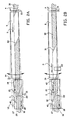
- Figure 1 schematically shows a top view of a first embodiment of a splicer 1 for splicing strips of in rubber material embedded cords to each other according to the invention.
- the in the rubber material embedded cords may for instance be of steel or the like. Such cords reinforce the strips.
- the splicer 1 comprises a supply transport device 2 for supplying strips in a supply direction 3.
- the supply transport device 2 comprises a first transport unit 4 and a second transport unit 5 that are in line with each other.
- the second transport unit 5 has an inlet end 9 and an outlet end 10.
- the splicer 1 comprises a splicing unit 6 for splicing strips to each other.
- the splicing unit 6 comprises a splicing table 7 and a splicing machine 8 placed over the splicing table 7.
- a splice line 12 is determined by the splicing machine 8.
- the first transport unit 4 supplies strips to the second transport unit 5.
- the second transport unit 5 subsequently transports the strips further to the splicing table 7 of the splicing unit 6.
- the position of a strip to be supplied to the splicing table 7 can be adjusted to the position of a strip that is already present on the splicing table 7, so that these two strips can be spliced to each other more accurately, because the outlet end 10 of the second transport unit 5 and the splicing table 7 are laterally, that means transverse to the transport direction, movable with respect to each other.
- the second transport unit 5 can be laterally movable in its entirety.
- the second transport unit can be rotatably mounted around its inlet end 9.
- the splicing table 7 can be laterally movable in its entirety.
- a first sensor 13 is provided for determining the centre of the strip between the first transport unit 4 and the second transport unit 5. Said sensor 13 generates a starting position signal. In this way a strip can already be positioned at a very early stage, which increases the accuracy of the final splice.
- a second sensor 14 determines the position of the strip between the second transport unit 5 and the splicing table 7. Said second sensor 14 also generates a middle position signal.
- a third sensor 15 determines the position of the strip under the splice line 12 and also generates an end position signal.
- a computer having a file in which a target position has been included, and a comparer for comparing a position signal generated by one of the sensors and fed into the computer, with the target position and for issuing a control signal for controlling the relative lateral position of the splicing table 7 and/or the second transport unit 5, as will be elucidated below.
- a comparer for comparing a position signal generated by one of the sensors and fed into the computer, with the target position and for issuing a control signal for controlling the relative lateral position of the splicing table 7 and/or the second transport unit 5, as will be elucidated below.
- a very accurate splice can be obtained when the target position is the centre of the splice line 12. Especially in case of narrow and/or limp strips it is extra advantageous when the splicing machine 8 is rotatably mounted, and the point of rotation is formed by the middle of the splice line 12. As discussed above, in this way possible deviations are distributed over both sides of the strips and the resulting (halved) deviations are acceptable indeed.
- the invention also offers the possibility to reduce inaccuracies in the positioning as a result of sliding the strips over the splicing table 7, as shown in figure 2.
- the splicing table 7 has an imaginary longitudinal centre line 16 dividing the splicing table 7 in a first splicing table half 17 and a second splicing table half 18.
- the splicing table 7 further has an inlet end 19 and an outlet end 20.
- a first splicing table transport unit 21 is placed on the first splicing table half 17, and extends from the inlet end 19 of the splicing table 7 up to a distance from the inlet end 19 of the splicing table 7. Because of this, half of a supplied strip can be placed on the first splicing table transport unit 21, and for instance by synchronised drive with the second transport unit 5 the strip can be supplied in position on the splicing table 7 without loss of accuracy.
- the above-mentioned transport units and the like are for instance formed by conveyor belts, possibly provided with means for generating a vacuum or a magnetic field for transporting the strips slip-free.
- the conveyor belts 4, 5, 21 and 22 can be controlled as well by means of the computer and the data obtained by the sensors 13, 14 and 15.
- the strip 30 is laterally actively directed towards the target position on the splice line 12.
- the position of the strip 30 is measured beforehand by the sensor 13 at the location where the strip 30 is transferred on the second transport unit 5, also called centring conveyor.
- This offers the opportunity to direct the leading tip 31 (figure 2B) to the lateral target position during transport of the strip 30 to the splicing table 7.
- the lateral position of the rear side of the strip 30 is also measured during transfer to the centring conveyor 5, and directed towards the target position during transport.
- the stop position of the strip 30 on the splicing table 7 is controlled by the sensors 14 and 15 (for clarity's sake only shown in figure 2A), on the basis of which data the drive of the conveyor belt 4 and the discharge transport device for discharging the strips spliced together is regulated.
- splicing table transport units 21 and 22 are provided.
- the splicing table transport unit 21 preferably moves synchronously with centring conveyor 5, and half of the strip 30, as seen in transverse direction, is retained by the splicing table transport unit 21.
- the other half of the strip to be supplied slides over the splicing table 7.
- the strips 30, 40, spliced together are passed on by driving all transport units 5, 21 and 22, whereas positioning the end tip of the discharged strip 30 takes place by means of the transport unit 22.
- the splicing table transport units 21 and 22 only partially extend over the splicing table 7, it is also possible alternatively that they extend over the entire length of the splicing table 7.
- the operation in principle remains the same, on the understanding that the first half of the splicing table transport unit 21 needs to have sufficient clamping force to supply the material slip-free, whereas the second half has to be able to run under the already passed strip 40, without the strip position being changed.
- means for generating a vacuum of magnetic field for retaining the strip may be provided in the first part, and a so-called air-floatation system may be provided in the second part.
- the placing of the means for generating a vacuum or magnetic field and the air-floatation system is the other way round.
- FIG 2C the situation is shown in which by means of the sensor 15 the position of the strip 40 is determined again.
- the splice table transport units 21 and 22 still work synchronously, but decelerate to a speed zero.
- the conveyor 5 decelerates to speed zero as well. Because of the low speed the measuring accuracy of the position of the end 42 with respect to the splice line 12 is large as well, and the passed on end 42 can be positioned exactly towards the splicing position.
- the moment in which the sensor 15 no longer detects material is also the moment in which the speed of the splicing table transport unit 21 is adjusted to the one of the centring conveyor 5.
- FIG 2D the situation is described in which the supplied strip 30 is detected by the sensor 14.
- the splicing table transport units 21 and 22 decelerate synchronously to position the strip 30 towards the stop position.
- the positioning may be adjusted.
- the lateral position of the trailing end 32 has been measured by the sensor 13, and thus its centre line as well can exactly be directed towards the middle of the splicing table 7.
- both the lateral and the length position of the strips to be spliced are controlled up to the splice line by the splicing table transport units 21 and 22, independent of the angle or width of the material.
Landscapes
- Engineering & Computer Science (AREA)
- Mechanical Engineering (AREA)
- Textile Engineering (AREA)
- Tyre Moulding (AREA)
- Lining Or Joining Of Plastics Or The Like (AREA)
- Replacement Of Web Rolls (AREA)
Claims (13)
- Spleissanlage (6) zum Verspleissen von Streifen (30) von in Gummimaterial eingebettetem Kordmaterial miteinander, wobei die Spleissanlage einen Spleisstisch (7) und eine Spleissmaschine (8) umfasst, die über dem Spleisstisch angeordnet ist und eine Spleiss-Linie bestimmt, und wobei der Spleisstisch (7) mit einer imaginären Längsachse (16), die den Spleisstisch in eine erste Spleisstisch-Hälfte (17) und eine zweite Spleisstisch-Hälfte (18) teilt, sowie mit einer Einlauf-Stirnseite (19) und einer Auslauf-Stirnseite (20) versehen ist, wobei ein erste Spleisstisch-Transporteinrichtung (21) auf der ersten Spleisstisch-Hälfte (17) angeordnet ist, dadurch gekennzeichnet, dass sich diese erste Spleisstisch-Transport-einrichtung von der Einlauf-Stirnseite (19) des Spleisstisches (7) bis zu einer bestimmten Entfernung von der Einlauf-Stirnseite (19) des Spleisstisches (7) erstreckt.
- Spleissanlage nach Anspruch 1, dadurch gekennzeichnet, dass die Spleissanlage (6) außerdem eine zweite Spleisstisch-Transporteinrichtung (22) hat, die auf der zweiten Spleisstisch-Hälfte (18) angeordnet ist, wobei sich die zweite Spleisstisch-Transporteinrichtung (22) von der Auslauf-Stirnseite (20) des Spleisstisches (7) her erstreckt.
- Spleissanlage nach Anspruch 2, dadurch gekennzeichnet, dass die erste Spleisstisch-Transporteinrichtung (21) und die zweite Spleisstisch-Transporteinrichtung (22) einen synchronisierten Antrieb haben.
- Spleissanlage nach Anspruch 2 oder 3, dadurch gekennzeichnet, dass die erste und die zweite Spleisstisch-Transporteinrichtung (21, 22) zum Teil in Längsrichtung über den Spleisstisch (7) verlaufen.
- Spleissanlage nach Anspruch 4, dadurch gekennzeichnet, dass die erste und die zweite Spleisstisch-Transporteinrichtung (21, 22) in Längsrichtung über den Spleisstisch (7) verlaufen und in einem bestimmten Abstand voneinander enden, und zwar beide vorzugsweise vor der Spleiss-Linie.
- Spleissanlage nach Anspruch 2 oder 3, dadurch gekennzeichnet, dass die erste und die zweite Spleisstisch-Transporteinrichtung (21, 22) sich in Längsrichtung über die völlige Länge des Spleisstisches (7) erstrecken.
- Spleissanlage nach den Ansprüchen 2 - 6, dadurch gekennzeichnet, dass die erste und die zweite Spleisstisch-Transporteinrichtung (21, 22) Vorrichtungen zum Bereitstellen einer Klemmkraft haben, die ausreicht, um die Streifen rutschfrei zuzuführen, wobei diese Vorrichtungen vorzugsweise solche sind, die ein Vakuum oder ein Magnetfeld erzeugen.
- Spleissanlage nach Anspruch 6 oder Anspruch 7, wenn von Anspruch 6 abhängig, dadurch gekennzeichnet, dass die zweite Hälfte der ersten Spleisstisch-Transporteinrichtung (21) ein Luftkissensystem hat, das es der Spleisstisch-Transport-einrichtung ermöglicht, sich unter einem bereits durchgelaufenen Streifen zu bewegen, ohne seine Position zu ändern.
- Spleissanlage nach einem der vorhergehenden Ansprüche 2 bis 8, dadurch gekennzeichnet, dass die erste und die zweite Spleisstisch-Transporteinrichtung (21, 22) Förderbänder umfassen.
- Spleissanlage nach einem der vorhergehenden Ansprüche, dadurch gekennzeichnet, dass ein Sensor vorgesehen ist, der die Position des Streifens unter der Spleiss-Linie bestimmen kann und der ein Signal "Endposition" erzeugen kann.
- Spleissanlage nach den Ansprüchen 2 - 10, dadurch gekennzeichnet, dass die erste und die zweite Spleisstisch-Transporteinrichtung in synchronisierter Weise bis zur Geschwindigkeit Null abbremsen können, so dass das Verspleissen der Streifen miteinander bei stillstehenden Streifen stattfindet.
- Verfahren zum Verspleissen von Streifen (30) von in Gummimaterial eingebettetem Kordmaterial miteinander, das eine Spleissanlage entsprechend einem der vorhergehenden Ansprüche 1 bis 11 verwendet, bei dem die hintere Spitze (42) eines auslaufenden Streifens (40) mit der vorderen Spitze (31) eines zugeführten Streifens (30) verspleisst wird, dadurch gekennzeichnet, dass die vordere Spitze (31) des zugeführten Streifens (30) mittels der ersten Spleisstisch-Transporteinrichtung (21) positioniert wird, während seine Position mit Hilfe eines Sensors (15) überwacht wird.
- Verfahren nach Anspruch 12, bei dem die Spleissanlage (6) außerdem eine zweite Spleisstisch-Transporteinrichtung (22) umfasst, die auf der zweiten Hälfte (18) des Spleisstisches angeordnet ist, wobei sich die zweite Spleisstisch-Transporteinrichtung (22) vom Auslass-Ende (20) des Spleisstisches (7) her erstreckt, dadurch gekennzeichnet, dass- zuerst die hintere Spitze (42) des auslaufenden Streifens (40) mittels der zweiten Spleisstisch-Transporteinrichtung (22) positioniert wird im Hinblick auf die Spleiss-Linie, während ihre Position mit Hilfe des Sensors überwacht wird;- anschließend die vordere Spitze (31) des zugeführten Streifens (30) positioniert wird, während die hintere Spitze (42) des auslaufenden Streifens (40) in ihrer Position auf der ersten Spleisstisch-Transporteinrichtung (21) festgehalten wird.
Applications Claiming Priority (3)
| Application Number | Priority Date | Filing Date | Title |
|---|---|---|---|
| NL1015250A NL1015250C2 (nl) | 2000-05-19 | 2000-05-19 | Lasinrichting voor het aan elkaar lassen van stroken van in rubbermateriaal ingebedde koorden. |
| NL1015250 | 2000-05-19 | ||
| EP01932414A EP1282505B1 (de) | 2000-05-19 | 2001-05-21 | Spleissvorrichtung zum spleissen von gummibeschichteten kordbandstreifen |
Related Parent Applications (2)
| Application Number | Title | Priority Date | Filing Date |
|---|---|---|---|
| EP01932414.4 Division | 2001-05-21 | ||
| EP01932414A Division EP1282505B1 (de) | 2000-05-19 | 2001-05-21 | Spleissvorrichtung zum spleissen von gummibeschichteten kordbandstreifen |
Publications (3)
| Publication Number | Publication Date |
|---|---|
| EP1422047A2 EP1422047A2 (de) | 2004-05-26 |
| EP1422047A3 EP1422047A3 (de) | 2005-07-13 |
| EP1422047B1 true EP1422047B1 (de) | 2007-08-29 |
Family
ID=19771410
Family Applications (2)
| Application Number | Title | Priority Date | Filing Date |
|---|---|---|---|
| EP01932414A Expired - Lifetime EP1282505B1 (de) | 2000-05-19 | 2001-05-21 | Spleissvorrichtung zum spleissen von gummibeschichteten kordbandstreifen |
| EP04075368A Expired - Lifetime EP1422047B1 (de) | 2000-05-19 | 2001-05-21 | Spleissvorrichtung für Gummistreifen mit eingebetteten Korden |
Family Applications Before (1)
| Application Number | Title | Priority Date | Filing Date |
|---|---|---|---|
| EP01932414A Expired - Lifetime EP1282505B1 (de) | 2000-05-19 | 2001-05-21 | Spleissvorrichtung zum spleissen von gummibeschichteten kordbandstreifen |
Country Status (11)
| Country | Link |
|---|---|
| US (2) | US6796354B2 (de) |
| EP (2) | EP1282505B1 (de) |
| JP (2) | JP3953818B2 (de) |
| KR (1) | KR100777995B1 (de) |
| CN (1) | CN1208179C (de) |
| AU (1) | AU2001258941A1 (de) |
| DE (2) | DE60130268T2 (de) |
| NL (1) | NL1015250C2 (de) |
| RU (1) | RU2272778C2 (de) |
| SK (1) | SK16422002A3 (de) |
| WO (1) | WO2001089813A1 (de) |
Families Citing this family (10)
| Publication number | Priority date | Publication date | Assignee | Title |
|---|---|---|---|---|
| NL1022246C2 (nl) * | 2002-12-23 | 2004-06-24 | Vmi Epe Holland | Inrichting en werkwijze voor het maken van een gordellaag. |
| RU2359829C2 (ru) * | 2004-03-18 | 2009-06-27 | ВМИ ЭПЕ Холланд Б.В. | Режущее устройство, устройство и способ (варианты) для расположения брекерного слоя |
| US7441318B2 (en) * | 2005-02-09 | 2008-10-28 | The Goodyear Tire & Rubber Co | Method for detecting exposed metal cords in an elastomeric strip |
| US7497241B2 (en) * | 2005-07-27 | 2009-03-03 | The Steelastic Company, Llc | Tire belt machine |
| NL2005819C2 (nl) * | 2010-12-06 | 2012-06-07 | Vmi Holland Bv | Lasinrichting en werkwijze voor het aan elkaar lassen van stroken van rubbermateriaal. |
| NL2011764C2 (en) * | 2013-11-08 | 2015-05-11 | Vmi Holland Bv | Method for centering a tire component. |
| JP5802818B1 (ja) | 2014-10-29 | 2015-11-04 | 東芝産業機器システム株式会社 | 順送加工方法 |
| JP6696538B2 (ja) * | 2018-08-21 | 2020-05-20 | 横浜ゴム株式会社 | タイヤの製造方法および成形システム並びにタイヤ |
| DE102024130831A1 (de) | 2024-10-23 | 2026-04-23 | Fischer Tiretech Germany Gmbh | Spleißeinrichtung zum Spleißen von Bandstreifen, insbesondere klebrigen Cordbandstreifen |
| DE202024106085U1 (de) | 2024-10-23 | 2024-11-05 | Karl Eugen Fischer Gesellschaft mit beschränkter Haftung | Spleißeinrichtung zum Spleißen von Bandstreifen, insbesondere klebrigen Cordbandstreifen |
Family Cites Families (26)
| Publication number | Priority date | Publication date | Assignee | Title |
|---|---|---|---|---|
| US1189724A (en) * | 1915-06-28 | 1916-07-04 | Morgan & Wright | Apparatus for and process of cutting and reeling tire fabric. |
| US1961725A (en) * | 1927-07-30 | 1934-06-05 | Morgan & Wright | Apparatus for manufacturing tires |
| US2850277A (en) * | 1955-10-20 | 1958-09-02 | Goodyear Tire & Rubber | Strip aligning apparatus |
| US2947057A (en) * | 1956-02-03 | 1960-08-02 | Plainfield Patents Corp | Flexible web reeling and guiding mechanisms |
| US3859152A (en) * | 1970-02-11 | 1975-01-07 | Firestone Tire & Rubber Co | Tire fabric cutter |
| US3832261A (en) * | 1970-02-11 | 1974-08-27 | Firestone Tire & Rubber Co | Materials handling assembly |
| JPS5056908A (de) * | 1973-09-14 | 1975-05-19 | ||
| DE2628887A1 (de) * | 1976-06-26 | 1977-12-29 | Metzeler Kautschuk | Vorrichtung zum verbinden von stahlcordeinlagen fuer fahrzeugreifen |
| IT1134875B (it) * | 1980-12-23 | 1986-08-20 | Pirelli | Apparecchiatura per l'alimentazione di stratia di rinforzo nella fabbricazione di pneumatici |
| DE3113619C2 (de) * | 1981-04-03 | 1984-04-05 | G. O. Stumpf GmbH & Co KG, 7421 Mehrstetten | Vorrichtung zur Kantensteuerung für eine Legemaschine |
| DE3249634C2 (de) * | 1981-08-31 | 1992-01-02 | Sumitomo Rubber Industries Ltd., Kobe, Hyogo | Verfahren und Vorrichtung um Aufbringen von Reifenmaterial auf eine Reifenaufbautrommel |
| JPS5855235A (ja) * | 1981-09-29 | 1983-04-01 | Bridgestone Corp | リボン状材料の連続スプライス方法及び装置 |
| JPS5859829A (ja) * | 1981-10-06 | 1983-04-09 | Kobe Steel Ltd | ゴムシ−ト材料の搬送成形装置 |
| JPS61148037A (ja) * | 1984-12-24 | 1986-07-05 | Yokohama Rubber Co Ltd:The | タイヤ成形機に於けるタイヤ構成材料の自動供給装置 |
| JPS625844A (ja) * | 1985-07-02 | 1987-01-12 | Toyo Tire & Rubber Co Ltd | ゴム引きコ−ドの接合装置 |
| US4961813A (en) * | 1988-05-26 | 1990-10-09 | The Uniroyal Goodrich Tire Company | Servicer for tire building machine |
| US4976807A (en) * | 1989-04-12 | 1990-12-11 | Mitsubishi Jukogyo Kabushiki Kaisha | Apparatus for sticking a metal cord strip |
| JPH064293B2 (ja) * | 1989-12-21 | 1994-01-19 | 住友ゴム工業株式会社 | 帯状シート体成形方法及び成形装置 |
| EP0480672B1 (de) * | 1990-10-11 | 1995-06-14 | Sumitomo Rubber Industries Limited | Vorrichtung und Verfahren zum Herstellen von grünen Reifen |
| US5131971A (en) * | 1991-01-14 | 1992-07-21 | Elia Gerardo P | Apparatus for making a reinforced fabric from a ribbon of uncured elastomeric material |
| US5514233A (en) * | 1993-02-16 | 1996-05-07 | Mitsubishi Jukogyo Kabushiki Kaisha | Auto-splice device |
| DE4430453C2 (de) * | 1994-08-27 | 1996-08-14 | Fischer Maschf Karl E | Spleißmaschine |
| IT1286171B1 (it) * | 1996-07-12 | 1998-07-07 | Bridgestone Firestone Tech | Gruppo convogliatore di materiale in strisce. |
| DE19707367C1 (de) * | 1997-02-25 | 1998-06-10 | Fischer Maschf Karl E | Spleißmaschine |
| US6280556B1 (en) * | 1997-11-10 | 2001-08-28 | The Yokohama Rubber Co., Ltd. | Apparatus and method for aligning and splicing strip members |
| DE19938149C2 (de) * | 1999-08-16 | 2002-07-18 | Continental Ag | Zuführungseinrichtung für streifenförmige Reifenbauteile |
-
2000
- 2000-05-19 NL NL1015250A patent/NL1015250C2/nl not_active IP Right Cessation
-
2001
- 2001-05-21 AU AU2001258941A patent/AU2001258941A1/en not_active Abandoned
- 2001-05-21 JP JP2001586033A patent/JP3953818B2/ja not_active Expired - Fee Related
- 2001-05-21 EP EP01932414A patent/EP1282505B1/de not_active Expired - Lifetime
- 2001-05-21 DE DE60130268T patent/DE60130268T2/de not_active Expired - Fee Related
- 2001-05-21 EP EP04075368A patent/EP1422047B1/de not_active Expired - Lifetime
- 2001-05-21 WO PCT/NL2001/000385 patent/WO2001089813A1/en not_active Ceased
- 2001-05-21 DE DE60101962T patent/DE60101962T2/de not_active Expired - Fee Related
- 2001-05-21 SK SK1642-2002A patent/SK16422002A3/sk unknown
- 2001-05-21 KR KR1020027015588A patent/KR100777995B1/ko not_active Expired - Fee Related
- 2001-05-21 CN CNB018114180A patent/CN1208179C/zh not_active Expired - Fee Related
- 2001-05-21 RU RU2002134172/12A patent/RU2272778C2/ru not_active IP Right Cessation
-
2002
- 2002-11-15 US US10/298,260 patent/US6796354B2/en not_active Expired - Fee Related
-
2004
- 2004-04-14 US US10/823,978 patent/US20040188003A1/en not_active Abandoned
-
2007
- 2007-01-15 JP JP2007005594A patent/JP2007125895A/ja not_active Withdrawn
Also Published As
| Publication number | Publication date |
|---|---|
| US6796354B2 (en) | 2004-09-28 |
| KR20030017975A (ko) | 2003-03-04 |
| DE60130268D1 (de) | 2007-10-11 |
| DE60101962T2 (de) | 2004-10-28 |
| SK16422002A3 (sk) | 2003-05-02 |
| EP1422047A3 (de) | 2005-07-13 |
| RU2272778C2 (ru) | 2006-03-27 |
| DE60101962D1 (de) | 2004-03-11 |
| JP2007125895A (ja) | 2007-05-24 |
| JP2003534158A (ja) | 2003-11-18 |
| US20040188003A1 (en) | 2004-09-30 |
| NL1015250C2 (nl) | 2001-11-22 |
| WO2001089813A1 (en) | 2001-11-29 |
| US20030089459A1 (en) | 2003-05-15 |
| JP3953818B2 (ja) | 2007-08-08 |
| EP1282505A1 (de) | 2003-02-12 |
| CN1437529A (zh) | 2003-08-20 |
| EP1422047A2 (de) | 2004-05-26 |
| KR100777995B1 (ko) | 2007-11-27 |
| AU2001258941A1 (en) | 2001-12-03 |
| CN1208179C (zh) | 2005-06-29 |
| DE60130268T2 (de) | 2008-05-21 |
| EP1282505B1 (de) | 2004-02-04 |
Similar Documents
| Publication | Publication Date | Title |
|---|---|---|
| EP1422047B1 (de) | Spleissvorrichtung für Gummistreifen mit eingebetteten Korden | |
| JP4509111B2 (ja) | トレッド貼付け装置 | |
| CN104723589A (zh) | 用于拼接帘线带条的拼接装置 | |
| KR20060129091A (ko) | 컷팅 장치 | |
| US20090126874A1 (en) | Supply device for a tire-building drum | |
| US5175930A (en) | Method and apparatus for attaching belt-shaped member to forming drum | |
| KR20110015542A (ko) | 타이어 예비 조립체 제조 장치 | |
| EA015088B1 (ru) | Аппарат для соединения трубчатых сердечников | |
| CA1204794A (en) | Centering apparatus | |
| EP1313607B1 (de) | Vorrichtung zum spleissen von materialbahnen | |
| US4902372A (en) | Innerliner applicator | |
| EP0104303A2 (de) | Aufbringvorrichtung für Innenlagen | |
| CA1211354A (en) | Length correct apparatus | |
| EP4373659B1 (de) | Versorgungsvorrichtung für zwei reifenkomponenten und verfahren zur versorgung einer reifenaufbautrommel mit zwei reifenkomponenten | |
| JPH0584849A (ja) | 帯状材料の自動供給貼付け方法 | |
| KR200351470Y1 (ko) | 타이어 성형드럼의 카카스 공급장치 | |
| JP4167003B2 (ja) | 加硫済トレッド部材の切断方法 | |
| EP4489963B1 (de) | Schneidvorrichtung und verfahren zum schneiden eines reifenbauteils | |
| CN112512946A (zh) | 片体提供装置及片体提供方法 | |
| KR20260059461A (ko) | 밴드 스트립, 특히 접착성 코드 밴드 스트립을 스플라이싱하기 위한 스플라이싱 시스템 | |
| CN121946913A (zh) | 用于拼接带条、特别是粘性帘线带条的拼接设备 | |
| JPH01176546A (ja) | ベルト材のセンターリング方法及びその装置 |
Legal Events
| Date | Code | Title | Description |
|---|---|---|---|
| PUAI | Public reference made under article 153(3) epc to a published international application that has entered the european phase |
Free format text: ORIGINAL CODE: 0009012 |
|
| AC | Divisional application: reference to earlier application |
Ref document number: 1282505 Country of ref document: EP Kind code of ref document: P |
|
| AK | Designated contracting states |
Kind code of ref document: A2 Designated state(s): DE FR GB IT NL |
|
| PUAL | Search report despatched |
Free format text: ORIGINAL CODE: 0009013 |
|
| AK | Designated contracting states |
Kind code of ref document: A3 Designated state(s): DE FR GB IT NL |
|
| 17P | Request for examination filed |
Effective date: 20060105 |
|
| AKX | Designation fees paid |
Designated state(s): DE FR GB IT NL |
|
| 17Q | First examination report despatched |
Effective date: 20060317 |
|
| GRAP | Despatch of communication of intention to grant a patent |
Free format text: ORIGINAL CODE: EPIDOSNIGR1 |
|
| GRAS | Grant fee paid |
Free format text: ORIGINAL CODE: EPIDOSNIGR3 |
|
| GRAA | (expected) grant |
Free format text: ORIGINAL CODE: 0009210 |
|
| AC | Divisional application: reference to earlier application |
Ref document number: 1282505 Country of ref document: EP Kind code of ref document: P |
|
| AK | Designated contracting states |
Kind code of ref document: B1 Designated state(s): DE FR GB IT NL |
|
| REG | Reference to a national code |
Ref country code: GB Ref legal event code: FG4D |
|
| REF | Corresponds to: |
Ref document number: 60130268 Country of ref document: DE Date of ref document: 20071011 Kind code of ref document: P |
|
| ET | Fr: translation filed | ||
| PLBE | No opposition filed within time limit |
Free format text: ORIGINAL CODE: 0009261 |
|
| STAA | Information on the status of an ep patent application or granted ep patent |
Free format text: STATUS: NO OPPOSITION FILED WITHIN TIME LIMIT |
|
| PGFP | Annual fee paid to national office [announced via postgrant information from national office to epo] |
Ref country code: DE Payment date: 20080419 Year of fee payment: 8 |
|
| 26N | No opposition filed |
Effective date: 20080530 |
|
| PGFP | Annual fee paid to national office [announced via postgrant information from national office to epo] |
Ref country code: IT Payment date: 20080526 Year of fee payment: 8 |
|
| PGFP | Annual fee paid to national office [announced via postgrant information from national office to epo] |
Ref country code: NL Payment date: 20080530 Year of fee payment: 8 |
|
| PGFP | Annual fee paid to national office [announced via postgrant information from national office to epo] |
Ref country code: GB Payment date: 20080521 Year of fee payment: 8 |
|
| GBPC | Gb: european patent ceased through non-payment of renewal fee |
Effective date: 20090521 |
|
| NLV4 | Nl: lapsed or anulled due to non-payment of the annual fee |
Effective date: 20091201 |
|
| PG25 | Lapsed in a contracting state [announced via postgrant information from national office to epo] |
Ref country code: NL Free format text: LAPSE BECAUSE OF NON-PAYMENT OF DUE FEES Effective date: 20091201 |
|
| REG | Reference to a national code |
Ref country code: FR Ref legal event code: ST Effective date: 20100129 |
|
| PG25 | Lapsed in a contracting state [announced via postgrant information from national office to epo] |
Ref country code: FR Free format text: LAPSE BECAUSE OF NON-PAYMENT OF DUE FEES Effective date: 20090602 |
|
| PGFP | Annual fee paid to national office [announced via postgrant information from national office to epo] |
Ref country code: FR Payment date: 20080429 Year of fee payment: 8 |
|
| PG25 | Lapsed in a contracting state [announced via postgrant information from national office to epo] |
Ref country code: GB Free format text: LAPSE BECAUSE OF NON-PAYMENT OF DUE FEES Effective date: 20090521 |
|
| PG25 | Lapsed in a contracting state [announced via postgrant information from national office to epo] |
Ref country code: DE Free format text: LAPSE BECAUSE OF NON-PAYMENT OF DUE FEES Effective date: 20091201 |
|
| PG25 | Lapsed in a contracting state [announced via postgrant information from national office to epo] |
Ref country code: IT Free format text: LAPSE BECAUSE OF NON-PAYMENT OF DUE FEES Effective date: 20090521 |