EP1422737B1 - Magnétron et procédé de jonction d'élements d'un magnétron - Google Patents
Magnétron et procédé de jonction d'élements d'un magnétron Download PDFInfo
- Publication number
- EP1422737B1 EP1422737B1 EP03000535A EP03000535A EP1422737B1 EP 1422737 B1 EP1422737 B1 EP 1422737B1 EP 03000535 A EP03000535 A EP 03000535A EP 03000535 A EP03000535 A EP 03000535A EP 1422737 B1 EP1422737 B1 EP 1422737B1
- Authority
- EP
- European Patent Office
- Prior art keywords
- magnetron
- ceramic
- joint
- filament
- joining
- Prior art date
- Legal status (The legal status is an assumption and is not a legal conclusion. Google has not performed a legal analysis and makes no representation as to the accuracy of the status listed.)
- Expired - Lifetime
Links
- 238000005304 joining Methods 0.000 title claims description 44
- 238000000034 method Methods 0.000 title description 21
- 239000000463 material Substances 0.000 claims description 119
- 239000000919 ceramic Substances 0.000 claims description 89
- 238000003780 insertion Methods 0.000 claims description 43
- 230000037431 insertion Effects 0.000 claims description 43
- 229910052751 metal Inorganic materials 0.000 claims description 36
- 239000002184 metal Substances 0.000 claims description 36
- 239000000654 additive Substances 0.000 claims description 27
- 230000000996 additive effect Effects 0.000 claims description 21
- 239000010949 copper Substances 0.000 claims description 18
- RYGMFSIKBFXOCR-UHFFFAOYSA-N Copper Chemical compound [Cu] RYGMFSIKBFXOCR-UHFFFAOYSA-N 0.000 claims description 16
- 229910052802 copper Inorganic materials 0.000 claims description 16
- 229910052709 silver Inorganic materials 0.000 claims description 16
- 239000004332 silver Substances 0.000 claims description 16
- 230000008595 infiltration Effects 0.000 claims description 15
- 238000001764 infiltration Methods 0.000 claims description 15
- 239000000203 mixture Substances 0.000 claims description 15
- RTAQQCXQSZGOHL-UHFFFAOYSA-N Titanium Chemical compound [Ti] RTAQQCXQSZGOHL-UHFFFAOYSA-N 0.000 claims description 13
- 239000010936 titanium Substances 0.000 claims description 13
- 229910052719 titanium Inorganic materials 0.000 claims description 13
- ATJFFYVFTNAWJD-UHFFFAOYSA-N Tin Chemical compound [Sn] ATJFFYVFTNAWJD-UHFFFAOYSA-N 0.000 claims description 7
- QCWXUUIWCKQGHC-UHFFFAOYSA-N Zirconium Chemical compound [Zr] QCWXUUIWCKQGHC-UHFFFAOYSA-N 0.000 claims description 7
- 229910052718 tin Inorganic materials 0.000 claims description 7
- 229910052726 zirconium Inorganic materials 0.000 claims description 7
- 229910045601 alloy Inorganic materials 0.000 claims description 4
- 239000000956 alloy Substances 0.000 claims description 4
- NEIHULKJZQTQKJ-UHFFFAOYSA-N [Cu].[Ag] Chemical compound [Cu].[Ag] NEIHULKJZQTQKJ-UHFFFAOYSA-N 0.000 claims description 3
- 230000008569 process Effects 0.000 description 13
- 238000002844 melting Methods 0.000 description 12
- 230000008018 melting Effects 0.000 description 12
- BQCADISMDOOEFD-UHFFFAOYSA-N Silver Chemical compound [Ag] BQCADISMDOOEFD-UHFFFAOYSA-N 0.000 description 11
- 238000005219 brazing Methods 0.000 description 11
- 238000004519 manufacturing process Methods 0.000 description 10
- 238000009792 diffusion process Methods 0.000 description 8
- 229910052750 molybdenum Inorganic materials 0.000 description 6
- ZOKXTWBITQBERF-UHFFFAOYSA-N Molybdenum Chemical compound [Mo] ZOKXTWBITQBERF-UHFFFAOYSA-N 0.000 description 5
- 239000011733 molybdenum Substances 0.000 description 5
- 230000002265 prevention Effects 0.000 description 5
- XKRFYHLGVUSROY-UHFFFAOYSA-N Argon Chemical compound [Ar] XKRFYHLGVUSROY-UHFFFAOYSA-N 0.000 description 4
- 230000008901 benefit Effects 0.000 description 4
- 230000002950 deficient Effects 0.000 description 4
- 230000005684 electric field Effects 0.000 description 4
- 229910000831 Steel Inorganic materials 0.000 description 3
- 238000001816 cooling Methods 0.000 description 3
- 230000007547 defect Effects 0.000 description 3
- 230000000694 effects Effects 0.000 description 3
- 238000012423 maintenance Methods 0.000 description 3
- 230000009467 reduction Effects 0.000 description 3
- 239000010935 stainless steel Substances 0.000 description 3
- 229910001220 stainless steel Inorganic materials 0.000 description 3
- 239000010959 steel Substances 0.000 description 3
- PRPINYUDVPFIRX-UHFFFAOYSA-N 1-naphthaleneacetic acid Chemical compound C1=CC=C2C(CC(=O)O)=CC=CC2=C1 PRPINYUDVPFIRX-UHFFFAOYSA-N 0.000 description 2
- UFHFLCQGNIYNRP-UHFFFAOYSA-N Hydrogen Chemical compound [H][H] UFHFLCQGNIYNRP-UHFFFAOYSA-N 0.000 description 2
- 238000013459 approach Methods 0.000 description 2
- 229910052786 argon Inorganic materials 0.000 description 2
- 239000000945 filler Substances 0.000 description 2
- 230000003993 interaction Effects 0.000 description 2
- 239000011572 manganese Substances 0.000 description 2
- 238000012986 modification Methods 0.000 description 2
- 230000004048 modification Effects 0.000 description 2
- 230000003647 oxidation Effects 0.000 description 2
- 238000007254 oxidation reaction Methods 0.000 description 2
- 238000007747 plating Methods 0.000 description 2
- 229910052721 tungsten Inorganic materials 0.000 description 2
- PWHULOQIROXLJO-UHFFFAOYSA-N Manganese Chemical compound [Mn] PWHULOQIROXLJO-UHFFFAOYSA-N 0.000 description 1
- PQIJHIWFHSVPMH-UHFFFAOYSA-N [Cu].[Ag].[Sn] Chemical compound [Cu].[Ag].[Sn] PQIJHIWFHSVPMH-UHFFFAOYSA-N 0.000 description 1
- AHGIVYNZKJCSBA-UHFFFAOYSA-N [Ti].[Ag].[Cu] Chemical compound [Ti].[Ag].[Cu] AHGIVYNZKJCSBA-UHFFFAOYSA-N 0.000 description 1
- 230000009471 action Effects 0.000 description 1
- 230000015572 biosynthetic process Effects 0.000 description 1
- UQRBYHQTQUAYQZ-UHFFFAOYSA-N copper silver zirconium Chemical compound [Cu][Ag][Zr] UQRBYHQTQUAYQZ-UHFFFAOYSA-N 0.000 description 1
- 238000011118 depth filtration Methods 0.000 description 1
- 230000002708 enhancing effect Effects 0.000 description 1
- 239000006023 eutectic alloy Substances 0.000 description 1
- 238000002474 experimental method Methods 0.000 description 1
- 239000007789 gas Substances 0.000 description 1
- 238000010438 heat treatment Methods 0.000 description 1
- 229910000833 kovar Inorganic materials 0.000 description 1
- 239000007788 liquid Substances 0.000 description 1
- 229910052748 manganese Inorganic materials 0.000 description 1
- 238000005096 rolling process Methods 0.000 description 1
- 238000005476 soldering Methods 0.000 description 1
- 239000007787 solid Substances 0.000 description 1
- WFKWXMTUELFFGS-UHFFFAOYSA-N tungsten Chemical compound [W] WFKWXMTUELFFGS-UHFFFAOYSA-N 0.000 description 1
- 239000010937 tungsten Substances 0.000 description 1
- 238000003466 welding Methods 0.000 description 1
Images





Classifications
-
- H—ELECTRICITY
- H01—ELECTRIC ELEMENTS
- H01J—ELECTRIC DISCHARGE TUBES OR DISCHARGE LAMPS
- H01J23/00—Details of transit-time tubes of the types covered by group H01J25/00
- H01J23/14—Leading-in arrangements; Seals therefor
- H01J23/15—Means for preventing wave energy leakage structurally associated with tube leading-in arrangements, e.g. filters, chokes, attenuating devices
-
- H—ELECTRICITY
- H01—ELECTRIC ELEMENTS
- H01J—ELECTRIC DISCHARGE TUBES OR DISCHARGE LAMPS
- H01J9/00—Apparatus or processes specially adapted for the manufacture, installation, removal, maintenance of electric discharge tubes, discharge lamps, or parts thereof; Recovery of material from discharge tubes or lamps
- H01J9/24—Manufacture or joining of vessels, leading-in conductors or bases
- H01J9/26—Sealing together parts of vessels
Definitions
- the present invention relates to a magnetron which generates a microwave.
- the magnetron is applied to a microwave oven, a plasma lighting apparatus, a dryer, and other microwave systems.
- the magnetron When a power is applied to the magnetron, the magnetron, one of vacuum tubes, emits thermal electrons from a cathode, which produces a microwave by interaction of a strong electric field and a magnetic field.
- the microwave thus produced, is transmitted to outside of the magnetron through an antenna feeder, and is used as a heat source for heating an object.
- the magnetron is provided with an anode having an anode cylinder and an anode vain, a cathode having filament, a condenser, a choke coil, and leads for applying a power to the filament, one pair of magnets, one pair of pole pieces, and yoke for forming a magnetic circuit, an antenna feeder and an antenna cap for transmitting a generated microwave to outside of the magnetron.
- the magnetron by its nature, has a part that is required to be maintained at a vacuum, a joined state of component in which part gives a great influence to a performance of the magnetron.
- a joint of ceramic and a metal there is a joint of ceramic and a metal. Therefore, for maintaining a performance of the magnetron, a technique for precise joining of the metal component and the ceramic component is required.
- FIG. 1 illustrates joints of filament leads and external leads of a related art magnetron, schematically.
- FIG. 1 shows joints of one pair of filament leads 15 connected to a filament 11 and one pair of external leads 22 connected to a choke coil (not shown), and, together with this, shows joints of a lower seal 14 of a metal, forming a part of the vacuum space, and a ceramic stem 21, which will be explained.
- FIG. 1 there are an upper end shield 12 and a lower end shield 13 at top and bottom of the filament 11.
- the terminal plate 23 is on top of the ceramic stem 21 for connecting the one pair of filament leads 15 and the one pair of external leads 22, respectively.
- the terminal plate 23 is consist of two pieces which are not in contact, for connecting one of the filament leads 15 and one of the external leads 22 to one of the pieces, and connecting the other one of the filament leads 15 and the other one of the external leads 22 to the other one of the pieces.
- the one pair of filament leads 15 and the one pair of external leads 22 are connected from opposite sides.
- the metallizing is a process in which a paste containing molybdenum Mo and manganese Mn is applied to a surface of the ceramic, and heated at an elevated temperature higher than 1600°C, for forming the metal film on the surface of the ceramic.
- the metallizing makes, not only the fabrication process complicate, but also a fabrication cost high, as an additional furnace is required.
- the terminal plate 23 is thin, and susceptible to deformation, to cause defects in the brazing of the terminal plate 23 with the ceramic stem 21 frequently, and difficulty in correct positioning of the filament leads 15, resulting in poor reliability and performance of the magnetron.
- Patent application JP 61 006 266 A discloses the use of a metal plating on Tungsten or Molybdenum rods for improving the brazing property and reducing the brazing temperature when using silver brazing filler metal.
- the metal plating is applied to the leading rods and made to diffuse into the rod material (W, Mo) by a temperature of 770°C ⁇ 30°C.
- XP-2071090 discloses the use of a silver-copper eutectic alloy with titanium content applied on a Kovar structure.
- the present invention is directed to a magnetron that substantially obviates one or more of the problems due to limitations and disadvantages of the related art.
- An object of the present invention is to provide a magnetron which can prevent vacuum leakage caused by defective joining between components.
- Another object of the present invention is to provide a magnetron which can assemble components with easy.
- the present invention provides a magnetron as disclosed in claim 1.
- the joint is provided at a part between an upper seal on top of the anode cylinder and an upper ceramic at a bottom of the antenna cap, the joint is provided at a part between an exhaust pipe supporter of a metal, which supports an exhaust pipe that surrounds a top end of the antenna feeder, and an upper ceramic under the antenna cap, and the joint is provided at a part between a lower seal under the anode cylinder and a ceramic stem provided to permit pass of a plurality of leads.
- the joint is provided to an inside of an insertion hole in the ceramic stem the leads pass therethrough, and the joint is provided at a part between a filament lead connected to the filament and the external lead connected to the choke coil.
- the external lead has a diameter the same with, or greater than a diameter of the filament lead, the external lead has a recess in an end thereof, for insertion of an end of the filament lead, and the filament lead has a depth of recess in an end thereof, and the external lead has a tip at an end thereof for insertion into the recess.
- the joining material is an alloy of silver-copper-an additive.
- the additive has a content of 1 ⁇ 10wt%.
- the joining material has a composition ratio of silver : copper : additive of 60 ⁇ 80 wt% : 10 ⁇ 39 wt% : 1 ⁇ 10 wt%.
- the additive is a material selected from at least one of titanium, tin, and zirconium, wherein the joining material may have a composition ratio of silver : copper : titanium of 60 ⁇ 80 wt% : 10 ⁇ 39 wt% : 1 ⁇ 10 wt%, a composition ratio of silver : copper : tin of 60 ⁇ 80 wt% : 10 ⁇ 39 wt% : 1 ⁇ 10 wt%, a composition ratio of silver : copper : zirconium of 60 ⁇ 80 wt% : 10 ⁇ 39 wt% : 1 ⁇ 10 wt%, or a composition ratio of silver : copper : titanium of 60 ⁇ 68 wt% : 27 ⁇ 33 wt% : 2 ⁇ 5 wt%.
- a method for joining magnetron components comprising the steps of (a) providing a joining material at parts to be joined inclusive of parts between a metal component and a ceramic component, and between a filament lead and an external lead, (b) exposing the joining material to a preset temperature and a preset environment, for diffusing the joining material into the part to be joined, to infiltrate into an inner part of the ceramic component, and (c) cooling down the joining material, to join the part to be joined.
- the step (a) includes the steps of (a1) providing the joining material at a part between a lower seal under the anode cylinder and a ceramic stem, (a2) providing the joining material at a part between an upper seal on top of the anode cylinder and an upper ceramic under the antenna cap, (a3) providing the joining material at parts between an insertion hole in the ceramic stem and a filament lead passed through the insertion hole, and between the insertion hole and an external lead passed through the insertion hole, and (a4) providing the joining material at a part between the filament lead and the external lead.
- the step (a3) includes the steps of rolling a sheet of the insertion material rolled into a cylindrical form, and inserting into the insertion hole, to provide the joining material to an inside wall surface of the insertion hole, and inserting the filament lead and the external leads into the insertion hole from opposite sides of the insertion hole through an inside of the cylindrical joint material.
- the step (a3) includes the steps of inserting a cylindrical form of the joining material already prepared into the insertion hole, to provide the joining material to an inside wall surface of the insertion hole, and inserting the filament lead and the external leads into the insertion hole from opposite sides of the insertion hole through an inside of the cylindrical joint material.
- the step (a4) includes the steps of forming a depth of recess in an end of the external lead, placing the joining material in the recess, and inserting an end of the filament lead into the recess.
- the step (a4) includes the steps of forming a recess in an end of the filament lead, and forming a tip at an end of the external lead, placing the joining material in. the recess, and inserting the tip into the recess.
- the step (a) includes the step of providing a joining material to a thickness of 50 ⁇ 200 ⁇ m.
- the step (b) includes the step of exposing the joining material to a temperature ranging 800 ⁇ 1000°C, for diffusing, and infiltrating the joining material, wherein the step (b) includes the step of exposing the joining material to a vacuum, for diffusing, and infiltrating the joining material, when the vacuum is 1 ⁇ 10 -3 ⁇ 1 ⁇ 10 -5 torr.
- the step (b) includes the step of exposing the joining material to hydrogen gas, for diffusing, and infiltrating the joining material, or the step (b) includes the step of exposing the joining material to argon, for diffusing, and infiltrating the joining material.
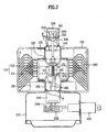
- the anode 110 includes an anode cylinder 111 and anode vanes 112.
- the anode cylinder 111 is cylindrical with opened top and bottom.
- the anode vanes 112 are projected in a radial direction from an inside circumference of the anode cylinder 111. Spaces between adjacent anode vanes 112 for resonant cavities.
- the filament 120 a cathode, is fitted in a center space of the plurality of vanes 112, with an interaction space provided between the filament 120 and ends of the anode vanes 112, in which electric field and magnetic field interact.
- an upper seal 140 and a lower seal 150 fitted to top and bottom of the anode cylinder 111 both are cylindrical containers of metal.
- the upper seal 140 and the lower seal 150 seal between the top of the anode cylinder 111 and an upper ceramic 330 to be explained later, and between the bottom of the anode cylinder 111 and a ceramic stem 240 to be explained later, respectively.
- the yoke 101 forms a magnetic circuit, together with the upper pole piece 133 and the lower pole piece 134.
- a filter box 210 under the yoke 101 for holding the ceramic stem 240 and the choke coil 230, and there is a condenser 220 at one side of the filter box 210.
- the condenser 220 is connected to the choke coil 230 in the filter box 210, for applying a power to the filament 120.
- an antenna feeder 310 fitted such that a lower end thereof is connected to any one of the anode vanes 112, and an upper end thereof is connected to a tip-off 341 at a top end of an exhaust pipe 340.
- the exhaust pipe 340 is supported on an exhaust pipe supporter 350 fixed to the top of the ceramic 330.
- an antenna cap 320 fitted to enclose the exhaust pipe 340 and the tip-off 341.
- the upper ceramic 330 is fitted between a lower end of the antenna cap 320 and the upper seal 140.
- the ceramic stem 240 and the lower seal 150 of metal, the upper ceramic 330 and the upper seal 140 of metal, and the upper ceramic 330 of ceramic and the exhaust pipe supporter 350 of metal are joined with a joint material 'F'.
- the joint material 'F' is provided to joint parts between metal components and. ceramic components in the magnetron, i.e., a joint part between the exhaust pipe supporter 350 and the upper ceramic 330, a joint part between the upper seal 140 and the upper ceramic 330, and a joint part between the lower seal 150 and the ceramic stem 240, and made to diffuse under preset temperature, and environment, to infiltrate into an inner part of the ceramic component, and join the two components.
- the magnetron of the present invention in which the two components are joined thus requires no formation of the metal film on the surfaces of the upper ceramic 330 and the ceramic stem 240, of ceramic, by metallizing in advance.
- the joint material 'F' of the present invention is, not applied by a process, such as soldering or the like, but a kind of active brazing filler which is activated by a given external condition in a state the joint material is provided to the joint part in advance, and diffused to infiltrate into an inner part of the ceramic component.
- This joining principle of the present invention is identical to the diffusion welding principle.
- the joint material 'F' of the present invention is also, provided to the joint part of the filament leads 160 and the external leads 250, and used in joining the two components, which will be explained with reference to FIGS. 3 - 5 .
- the filament leads 160 and the external leads 250 are formed, not as one unit, but individually, and joined, because it is economical that, while minimizing lengths of the filament leads 160 of expensive molybdenum, the external leads 250 are formed of an inexpensive alternative material, such as stainless steel or steel, and the two components are joined together.
- FIG. 3 illustrates a section showing joints of filament leads and external leads of a magnetron in accordance with a first preferred embodiment of the present invention.
- the joint material 'F' is provided between the filament leads 160 and the external leads 250, and between the filament leads 160 and the insertion holes 241, and the external leads 250 and the insertions holes 241.
- the joint material is provided in the insertion hole 241 for prevention of leakage of the vacuum after the joining.
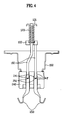
- FIG. 4 illustrates a section showing joints of filament leads and external leads of a magnetron in accordance with a second preferred embodiment of the present invention.
- each of the insertion holes 241 has an upper part, and a lower part having a diameter larger than the upper part, for receiving an external lead 250 having a diameter larger than the filament lead 160.
- This is for fabricating the filament leads 160 of, in general, expensive molybdenum smaller and fabricating the external leads of inexpensive stainless steel or steel, for reduction of cost. For close joining of the two different diametered leads, the following joining is required.
- the external lead 250 has a depth of recess 251 in an end part thereof, into which an end of the filament lead 160 are inserted and joined firmly with the joint material 'F'.
- the recess 251 has an inside diameter slightly larger than a diameter of the filament lead 160, and the joint material is provided to an inside of the recess 251, an upper part, and a lower part of the insertion hole 241.
- FIG. 5 illustrates a section showing joints of filament leads and external leads of a magnetron in accordance with a third preferred embodiment of the present invention.
- the filament lead 160 has a depth of recess 161 in an end thereof, and the external lead has a tip in conformity with the recess 161.
- the joint material 'F' is provided to an inside of the recess 161, an upper part and a lower part of the insertion hole 241.
- the direct joining of the one pair of filament leads 160 and the one pair of external leads 250 within the insertion holes 241 in the ceramic stem 240 facilitates an easy joining and prevents vacuum leakage caused by defective joining.
- the joint material 'F' is an alloy consisting of silver and copper as main composition taking a joint strength and air tightness into account, added with additives for making diffusion and infiltration into the ceramic mother member possible and enhancing the joint strength.
- the additives may be selected from a group of material including titanium, tin, and zirconium.
- the joint material an alloy of silver-copper-additives, includes 1 ⁇ 10wt% of additives, in more detail, 60 ⁇ 80wt% of silver, 10 ⁇ 39wt% of copper, and 1 ⁇ 10% of additives selected from a group of material including titanium, tin, and zirconium.
- the joint material 'F' may be consist of 60 ⁇ 80wt% of silver, 10 ⁇ 39wt% of copper, and 1 ⁇ 10% titanium, if the joint material 'F' is composed of silver-copper-and titanium, the joint material 'F' may be consist of 60 ⁇ 80wt% of silver, 10 ⁇ 39wt% of copper, and 1 ⁇ 10% tin, if the joint material 'F' is composed of silver-copper-and tin, and the joint material 'F' may be consist of 60 ⁇ 80wt% of silver, 10 ⁇ 39wt% of copper, and 1 ⁇ 10% zirconium, if the joint material 'F' is composed of silver-copper-and zirconium.
- the additive content is higher than 10wt%, a substantial amount of the joint material 'F' is diffused, and infiltrates into the ceramic components, i.e., the upper ceramic 330, and the ceramic stem 240, and starts to cause cracks therein.
- the higher the additive content the more a number of the cracks, to fail maintenance of the vacuum.
- the stronger the joint strength excessive content, causing excessive infiltration into the ceramic components, results in occurrence of cracks in the ceramic components.
- the present invention suggests the additive contents to be in a range of 1wt% ⁇ 10wt%.
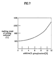
- a wt% of additive content there is another criterion required for determining a wt% of additive content. That is, if the wt% of the additive content, such as titanium, is increased only taking the joint strength into consideration even within the range no crack is occurred, there is another problem, i.e., a problem related to a joining temperature, is occurred.
- a melting point of the joint material rises, which has the following unfavorable effects. First, a higher temperature furnace is required as the melting point of the joint material is rises the more.
- the melting point of the joint material rises, to approach close to a melting point of a material used as a metal component of the mother members, such as Cu (MP:1080°C) and Fe (MP:1400°C), joining objects, the joining becomes meaningless if the mother member is damaged as the mother member starts to melt. Therefore, it is required to lower the melting point of the joint material, and, taking this aspect into consideration, a composition ratio of the additive is determined. Since the most ideal composition ratio of silver-copper having the lowest melting point is approx. 7 : 3, the present invention suggests silver-copper-additive (in case of titanium) of 65 ⁇ 68 : 27 ⁇ 33 : 2 ⁇ 5 wt% as an optimal weight ratio obtained from numerous experiments taking all above requirements into consideration.
- a material used as a metal component of the mother members such as Cu (MP:1080°C) and Fe (MP:1400°C)
- a joint material 'F' is provided to a joint part of filament leads 160 of molybdenum and the external leads 250 of stainless steel, or steel, and joint parts between metal components and ceramic components.
- the joint parts between metal components and ceramic components includes an insertion hole 241 space between the filament leads 160 and the ceramic stem 240, an insertion hole 241 space between the external leads 250 and the ceramic stem 240, a joint part of the lower seal 150 and the ceramic stem 240, and a joint part of the upper seal 140 and the upper ceramic 330, and the upper ceramic 330 and the exhaust pipe support 350.
- the filament lead 160 and the external leads 250 are inserted from opposite sides of the insertion hole 241 through an inside of the cylindrical joint material.
- the joint material 'F' may also be provided to the inside wall surface of the insertion hole 241 with the joint material divided into many pieces.
- the sheet of joint material may be rolled around an outer circumference of the filament lead 160 or the external lead 250 before inserting into the insertion hole 241.
- the joint material 'F' is also provided to the joint part between an end of the filament lead and an end of the external lead 250, both joined to an inside of the insertion hole.
- the joint material 'F' is provided to the joint part between the end of the filament lead and the end of the external lead 250, the following different methods may be applicable depending on forms of joining of the filament lead 160 and the external lead 250, one of which will be explained, with reference to FIG. 4 .
- a depth of recess 251 is formed in an end of the external lead 250 having a diameter greater than an end of the filament lead 160.
- the joint material 'F' is placed in the recess 251. Once the joint material 'F' is placed, the end of the filament lead 160 is inserted into the recess 251.
- a depth of recess 151 is formed in an end of the external lead 250. Then, a tip is formed at the end of the external lead 250 for insertion into the recess 161. There is no order of the steps of forming the recess 161 and the tip 252 in view of time, and, if necessary, the tip is formed at the filament lead 160 first, and the recess 161 may be formed in the external lead 250 next. Then, after the joint material is placed in the recess 161, the tip 252 is inserted in the recess 161, to finish providing the joint material.
- a thickness of the joint material 'F' gives a substantial influence to the joint strength and the air tightness. That is, if the joint material is too thick, a substantial amount of the joint material infiltrates into the ceramic component, to cause cracks in the ceramic component, and as a gap between the joined components becomes the larger, the air tightness becomes the poorer. Opposite to this, if the joint material is too thin, the joint strength between the components becomes poor. Therefore, putting all this conditions together, it is preferable that the thickness of the joint material 'F' is 50 ⁇ 200 ⁇ m.
- the joint material 'F' When the placing of the joint material 'F' is finished, the joint material is exposed to a preset temperature and a preset environment, so that the joint material 'F' is diffused, and infiltrates into the joint part.
- the preset temperature and the preset environment applied to the joint material 'F' are major factors that influence activity of the joint material 'F'.
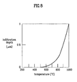
- FIG. 8 illustrates a graph showing a diffusion depth of a joint material into a joining component versus a temperature in accordance with a preferred embodiment of the present invention, wherein it can be noted that an infiltration depth and infiltration rate of the joint material are influenced from the temperature.
- FIG. 8 illustrates an example when a ratio of silver-copper-titan composition of the joint material is 67:30:3 wt%, where the ordinate represents a depth of infiltration, and the abscissa represent the temperature.
- the joint material starts solid state diffusion in the vicinity of 500°C, and starts liquid state diffusion at a temperature higher than approx.
- the exposure temperature is lower than melting points of metallic base members for avoiding thermal deformation and melting of the metallic members adjacent to the joint material, such as the upper seal 140, the lower seal 150, and the exhaust pipe supporter 350. Therefore, the exposure temperature of the joint material 'F' is suggested to be 800 ⁇ 1000°C in the present invention.
- FIG. 9A illustrates a photograph showing good joint of an actual joint part
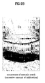
- FIG. 9B illustrates a photograph showing poor joint of an actual joint part caused by excessive diffusion of a joining member.
- FIG. 9A illustrates a photograph of a specimen showing a good joint of coalesced copper Cu and ceramic, where a joint indicated by an arrow is a uniform.
- FIG. 9B illustrates the joining material infiltrated into the ceramic component to a substantial depth, to form one more non-uniform boundary layer in a lower side, to cause cracks due to excessive infiltration. Therefore, a good joint can be provided only when the joining is carried out by a method suggested in the present invention considering above various conditions.
- the joining material 'F' may be exposed a vacuum along with the temperature, for prevention of oxidation and activity of the joining material 'F'. It is required that the joining material is joined at a vacuum higher than at least 1 ⁇ 10 -3 torr for effective prevention of joint defect caused by oxidation, and an optimal condition is joining at a vacuum in a range of 1 ⁇ 10 -5 torr, ideally.
- the joining of the joining material 'F' is carried out in a condition the joining material 'F' is exposed to above temperature, as well as hydrogen gas and or argon gas.
- the joining of the joint part is finished by cooling down the joining material 'F'.
- the joining material may be cooled down at a room temperature naturally, or artificially by an external heat source.
- the electric field and the magnetic field interact in an action space between edges of the anode vanes 112 and the filament 120, to generate a microwave.
- the microwave generated thus is transmitted through the antenna feeder 310, and radiated to outside of the magnetron through the upper ceramic 330 and the antenna cap 320.
- the magnetron of the present invention has the following advantages.
- the infiltration type joining of the joining material 'F' between metal component and the ceramic component provides, not only a high joint strength, but also a high air tightness, thereby improving a reliability of the magnetron as the vacuum leakage caused by defective joint can be prevented.
- the joining of the filament lead 160 and the external lead 250, not through the additional terminal plate, but through the joining material 'F' permits a simple component assembly process, and a simple magnetron fabrication process.
- the infiltration type joining of the joining material 'F' between various metal components and the ceramic components permits to dispense with the metallizing process on a surface of the ceramic component, thereby permitting simplification of the fabrication process and reduction of a fabrication cost.
- the melting, and infiltrating of the joining material 'F' into the ceramic component at 800 ⁇ 1000°C permits to carry out the fabrication at a low temperature furnace. Since the low temperature furnace is generally used in fabrication of the magnetron, the employment of the joining material 'F' of the present invention permits joining of different components only with existing equipment, without providing additional equipment. Therefore, the equipment cost can be saved.
- a Magnetron including an anode cylinder and anode vanes of an anode, a filament of a cathode, a condenser, a choke coil, and a plurality of leads for providing a power to the filament, magnets, pole pieces, and a yoke for forming a magnetic circuit, an antenna feeder and an antenna cap for transmitting a generated microwave to outside of the magnetron, and joints formed of a joining material between a metal component and a ceramic component of the magnetron, wherein the joining material is diffused between the metal component and the ceramic component, to infiltrate into an inner part of the ceramic component directly, thereby joining the two components, thereby improving a reliability of a magnetron, facilitating a simple component assembly process and a simple magnetron fabrication process, permitting simplification of the fabrication process and reduction of a fabrication cost, and saving the equipment cost as a high temperature furnace can be dispensed with.
Landscapes
- Engineering & Computer Science (AREA)
- Manufacturing & Machinery (AREA)
- Microwave Tubes (AREA)
- Resistance Heating (AREA)
- Ceramic Products (AREA)
- Manufacture Of Electron Tubes, Discharge Lamp Vessels, Lead-In Wires, And The Like (AREA)
Claims (14)
- Magnétron comprenant :un cylindre anodique (111) et des palettes anodiques (112) d'une anode;un filament (120) d'une cathode pour un magnétron;un condensateur (220), une bobine d'arrêt (230) et une pluralité de conducteurs (160, 250) pour fournir du courant au filament (120);des aimants (131), des pièces de pôle (133, 134) et une culasse (101) pour former un circuit magnétique;un alimentateur d'antenne (130) et un capuchon d'antenne (320) pour transmettre, à l'extérieur du magnétron, une microonde générée; etdes jointures formées d'un matériau de jointure (F) entre un composant métallique (140, 150, 160, 250) et un composant céramique (240, 330) du magnétron,le matériau de jointure (F) étant agencé entre le composant métallique (140, 150, 160, 250) et le composant céramique (240, 330), et étant diffusé pour s'infiltrer dans une partie intérieure du composant céramique (240, 330) directement, joignant ainsi les deux composants, dans lequel le matériau de jointure (F) est un alliage de argent-cuivre et un additif, et est diffusé dans la céramique à une profondeur d'infiltration sélectionnée dans la plage de 0,2 µm à 1,0 µm.
- Magnétron selon la revendication 1, dans lequel la jointure est prévue au niveau d'une partie entre un joint supérieur (140) sur le dessus du cylindre anodique (111) et une céramique supérieure au niveau d'un fond du capuchon d'antenne (320).
- Magnétron selon la revendication 1 ou la revendication 2, dans lequel la jointure est prévue au niveau d'une partie entre un support de tuyau d'échappement (350) d'un métal, qui supporte un tuyau d'échappement (340) qui entoure une extrémité supérieure de l'alimentateur d'antenne (310), et une céramique supérieure sous le capuchon d'antenne (320).
- Magnétron selon l'une des revendications 1 à 3, dans lequel la jointure est prévue au niveau d'une partie entre le joint inférieur (150) sous le cylindre anodique (111) et un tenon céramique (240) prévu pour permettre le passage d'une pluralité de conducteurs (160, 250).
- Magnétron selon l'une des revendications 1 à 4, dans lequel la jointure est prévue dans un intérieur d'un trou d'insertion (241) dans le tenon céramique (240) au travers duquel passent les conducteurs (160, 250).
- Magnétron selon l"une des revendications 1 à 5, dans lequel la jointure est prévue au niveau d'une partie entre un conducteur filament (160) connecté au filament (120) et le conducteur externe (250) connecté à la bobine d'arrêt (230).
- Magnétron selon la revendication 6, dans lequel le conducteur externe (250) a un diamètre identique ou plus grand qu'un diamètre du conducteur de filament (160).
- Magnétron selon la revendication 1, dans lequel l'additif a un contenu de 1 - 10% en poids.
- Magnétron selon la revendication 1 ou la revendication 8, dans lequel le matériau de jointure a un ratio de composition argent:cuivre:additif de 60 - 80% en poids : 10-39% en poids : 1 - 10% en poids.
- Magnétron selon la revendication 1, la revendication 8 ou la revendication 9, dans lequel l'additif est un matériau sélectionné parmi l'un au moins du titane, étain et zirconium.
- Magnétron selon la revendication 10, dans lequel le matériau de jointure a un ratio de composition argent: cuivre:titane de 60 - 80% en poids : 10 - 39% en poids : 1 - 10% en poids.
- Magnétron selon la revendication 10, dans lequel le matériau de jointure a un ratio de composition argent:cuivre:étain de 60 - 80% en poids : 10 - 39% en poids : 1 - 10% en poids.
- Magnétron selon la revendication 10, dans lequel le matériau de jointure a un ratio de composition argent:cuivre:zirconium de 60 - 80% en poids : 10 - 39% en poids : 1 - 10% en poids.
- Magnétron selon la revendication 10, dans lequel le matériau de jointure a un ratio de composition argent:cuivre:titane de 60 - 68% en poids : 27 - 33 % en poids : 2 - 5% en poids.
Applications Claiming Priority (2)
| Application Number | Priority Date | Filing Date | Title |
|---|---|---|---|
| KR10-2002-0072436A KR100493298B1 (ko) | 2002-11-20 | 2002-11-20 | 마그네트론 및 마그네트론 부재 간 접합 방법 |
| KR2002072436 | 2002-11-20 |
Publications (3)
| Publication Number | Publication Date |
|---|---|
| EP1422737A2 EP1422737A2 (fr) | 2004-05-26 |
| EP1422737A3 EP1422737A3 (fr) | 2006-06-21 |
| EP1422737B1 true EP1422737B1 (fr) | 2012-01-04 |
Family
ID=32226329
Family Applications (1)
| Application Number | Title | Priority Date | Filing Date |
|---|---|---|---|
| EP03000535A Expired - Lifetime EP1422737B1 (fr) | 2002-11-20 | 2003-01-09 | Magnétron et procédé de jonction d'élements d'un magnétron |
Country Status (5)
| Country | Link |
|---|---|
| US (1) | US6756735B2 (fr) |
| EP (1) | EP1422737B1 (fr) |
| JP (1) | JP2004172081A (fr) |
| KR (1) | KR100493298B1 (fr) |
| CN (1) | CN100587890C (fr) |
Families Citing this family (17)
| Publication number | Priority date | Publication date | Assignee | Title |
|---|---|---|---|---|
| KR100774467B1 (ko) * | 2005-12-27 | 2007-11-08 | 엘지전자 주식회사 | 마그네트론의 초크필터 |
| KR100700554B1 (ko) * | 2005-12-30 | 2007-03-28 | 엘지전자 주식회사 | 마그네트론 |
| JP4898316B2 (ja) * | 2006-06-19 | 2012-03-14 | 東芝ホクト電子株式会社 | マグネトロン |
| JP4503639B2 (ja) | 2007-09-11 | 2010-07-14 | 東芝ホクト電子株式会社 | 電子レンジ用マグネトロン |
| US8723419B2 (en) * | 2008-11-27 | 2014-05-13 | Panasonic Corporation | Magnetron and device using microwaves |
| JPWO2010073564A1 (ja) * | 2008-12-25 | 2012-06-07 | パナソニック株式会社 | マグネトロン及びマイクロ波利用機器 |
| JP2011113949A (ja) * | 2009-11-30 | 2011-06-09 | Panasonic Corp | マグネトロン及びマイクロ波利用機器 |
| JP5676899B2 (ja) * | 2010-03-25 | 2015-02-25 | 東芝ホクト電子株式会社 | マグネトロンおよびこれを用いた電子レンジ |
| GB201005450D0 (en) * | 2010-03-31 | 2010-05-19 | E2V Tech Uk Ltd | Magnetron |
| JP2014135161A (ja) * | 2013-01-09 | 2014-07-24 | Panasonic Corp | マグネトロン |
| CN103268848B (zh) * | 2013-05-31 | 2015-09-02 | 南京三乐电子信息产业集团有限公司 | 一种连续波磁控管阴极的制备方法 |
| JP6325345B2 (ja) * | 2014-05-28 | 2018-05-16 | 東芝ホクト電子株式会社 | マグネトロン |
| JP5805842B1 (ja) | 2014-12-03 | 2015-11-10 | 東芝ホクト電子株式会社 | マグネトロン |
| JP6607445B2 (ja) * | 2016-03-10 | 2019-11-20 | パナソニックIpマネジメント株式会社 | マグネトロン |
| CN112238274B (zh) * | 2020-08-07 | 2021-08-31 | 广东格兰仕微波炉电器制造有限公司 | 一种磁控管阴极组件的组装工艺 |
| CN112242282B (zh) * | 2020-08-07 | 2023-07-28 | 广东格兰仕微波炉电器制造有限公司 | 一种管芯组件的装配工艺 |
| WO2022108121A1 (fr) | 2020-11-18 | 2022-05-27 | 삼성전자 주식회사 | Dispositif électronique comprenant un écran enroulable |
Family Cites Families (27)
| Publication number | Priority date | Publication date | Assignee | Title |
|---|---|---|---|---|
| US3031737A (en) * | 1958-05-23 | 1962-05-01 | Edgerton Germeshausen And Grie | Metal-to-non-metal bond and method |
| GB925509A (en) * | 1959-07-29 | 1963-05-08 | Ass Elect Ind | Ceramic to metal bond |
| GB903824A (en) * | 1959-11-12 | 1962-08-22 | Ass Elect Ind | Improvements in ceramic-to-metal seals |
| US3795041A (en) * | 1970-09-24 | 1974-03-05 | Siemens Ag | Process for the production of metal-ceramic bond |
| JPS5721050A (en) * | 1980-07-14 | 1982-02-03 | Hitachi Ltd | Magnetron |
| JPS59137373A (ja) * | 1983-01-20 | 1984-08-07 | 日本特殊陶業株式会社 | セラミツクの接合方法 |
| JPS616266A (ja) | 1984-02-21 | 1986-01-11 | Toho Kinzoku Kk | 高融点金属材料 |
| US4740429A (en) * | 1985-07-22 | 1988-04-26 | Ngk Insulators, Ltd. | Metal-ceramic joined articles |
| JPS62289396A (ja) * | 1985-11-16 | 1987-12-16 | Sumitomo Cement Co Ltd | セラミツクスの接合方法 |
| JPH06101303B2 (ja) * | 1986-03-19 | 1994-12-12 | 株式会社日立製作所 | セラミツクスと金属の接合方法 |
| US4987035A (en) * | 1987-10-07 | 1991-01-22 | Norton Company | Ceramic joints |
| JPH01176284A (ja) * | 1987-12-28 | 1989-07-12 | Ngk Insulators Ltd | 金属・セラミックス接合体 |
| JPH02175674A (ja) * | 1988-12-28 | 1990-07-06 | Nippon Carbide Ind Co Inc | セラミックスと金属体との接合体及びその接合方法 |
| JPH0777989B2 (ja) * | 1989-01-25 | 1995-08-23 | 同和鉱業株式会社 | セラミックスと金属の接合体の製造法 |
| JP2840342B2 (ja) * | 1989-12-25 | 1998-12-24 | 三洋電機株式会社 | マグネトロン |
| JP2797020B2 (ja) * | 1990-07-12 | 1998-09-17 | 同和鉱業株式会社 | 窒化珪素と金属との接合体およびその製造法 |
| JP3195806B2 (ja) * | 1991-09-25 | 2001-08-06 | 日本発条株式会社 | セラミックコネクタ |
| US5368220A (en) * | 1992-08-04 | 1994-11-29 | Morgan Crucible Company Plc | Sealed conductive active alloy feedthroughs |
| JP3219516B2 (ja) * | 1993-01-26 | 2001-10-15 | 松下電器産業株式会社 | マグネトロン用陰極構体 |
| DE4319533A1 (de) * | 1993-06-12 | 1994-12-15 | Hoechst Ceram Tec Ag | Innenlötung bei Metall-Keramik-Verbunden |
| JP3495770B2 (ja) * | 1993-10-29 | 2004-02-09 | 日本発条株式会社 | セラミックス接合用ろう材 |
| JPH11130555A (ja) * | 1997-10-28 | 1999-05-18 | Kyocera Corp | セラミックス−銅接合用ろう材 |
| JP2000007471A (ja) * | 1998-06-18 | 2000-01-11 | Nippon Steel Corp | セラミックス部材 |
| KR20000003781U (ko) * | 1998-07-29 | 2000-02-25 | 윤종용 | 마그네트론 |
| JP2000156171A (ja) * | 1998-11-18 | 2000-06-06 | Matsushita Electronics Industry Corp | マグネトロン装置およびその製造方法 |
| JP2002056783A (ja) * | 2000-08-09 | 2002-02-22 | Sanyo Electric Co Ltd | マグネトロン |
| KR100437812B1 (ko) * | 2002-02-07 | 2004-06-30 | 엘지전자 주식회사 | 전자레인지용 마그네트론의 접합방법 및 접합부재 |
-
2002
- 2002-11-20 KR KR10-2002-0072436A patent/KR100493298B1/ko not_active Expired - Fee Related
-
2003
- 2003-01-09 EP EP03000535A patent/EP1422737B1/fr not_active Expired - Lifetime
- 2003-01-20 JP JP2003011067A patent/JP2004172081A/ja active Pending
- 2003-01-30 CN CN03103137A patent/CN100587890C/zh not_active Expired - Fee Related
- 2003-02-27 US US10/373,690 patent/US6756735B2/en not_active Expired - Lifetime
Non-Patent Citations (4)
| Title |
|---|
| "Diffusion joining zirconia ceramic body with another body - using aluminium or its alloy as insertion material", DERWENT, XP002378609 * |
| HUIJIE L ET AL: "DIFFUSION BONDING OF SIC CERAMIC TO TIAL-BASED ALLOY", JOURNAL OF MATERIALS SCIENCE LETTERS, CHAPMAN AND HALL LTD. LONDON, GB, vol. 20, no. 9, 1 May 2001 (2001-05-01), pages 815 - 817, XP001112190, ISSN: 0261-8028, DOI: 10.1023/A:1010950427079 * |
| LIU H J ET AL: "Interface structure and formation mechanism of diffusion-bonded joints of SiC ceramic to TiAl-based alloy", SCRIPTA MATERIALIA, ELSEVIER, AMSTERDAM, NL, vol. 43, no. 1, 30 June 2000 (2000-06-30), pages 49 - 53, XP004326092, ISSN: 1359-6462, DOI: 10.1016/S1359-6462(00)00360-2 * |
| MIZUHARA H ET AL: "CERAMIC-TO-METAL JOINING WITH ACTIVE BRAZING FILLER METAL", WELDING JOURNAL, AMERICAN WELDING SOCIETY, MIAMI, FL, US, vol. 64, no. 10, 1 October 1985 (1985-10-01), pages 27 - 32, XP002071090, ISSN: 0043-2296 * |
Also Published As
| Publication number | Publication date |
|---|---|
| EP1422737A2 (fr) | 2004-05-26 |
| US20040095073A1 (en) | 2004-05-20 |
| EP1422737A3 (fr) | 2006-06-21 |
| US6756735B2 (en) | 2004-06-29 |
| KR20040043960A (ko) | 2004-05-27 |
| CN100587890C (zh) | 2010-02-03 |
| KR100493298B1 (ko) | 2005-06-07 |
| JP2004172081A (ja) | 2004-06-17 |
| CN1503301A (zh) | 2004-06-09 |
Similar Documents
| Publication | Publication Date | Title |
|---|---|---|
| EP1422737A2 (fr) | Magnétron et procédé de jonction d'élements d'un magnétron | |
| US7997949B2 (en) | External-electrode discharge lamp with no light leakage from external electrode portion | |
| JP3594716B2 (ja) | 透過型x線管 | |
| JP2005302368A (ja) | 透過型x線管及びその製造方法 | |
| JP4982708B2 (ja) | 溶着箔およびこの箔を有するランプ | |
| US6375533B1 (en) | Electricity lead-in body for bulb and method for manufacturing the same | |
| JP3514568B2 (ja) | X線管の製造方法 | |
| US4608516A (en) | Electron tube having glass-to-metal-to-glass seal | |
| US4445873A (en) | Method of producing magnetrons | |
| CN116978762B (zh) | 阳极组件的兜料式焊接方法 | |
| CN115360563B (zh) | 一种微波组件内外导体的一体化装焊方法和系统 | |
| EP0343229B1 (fr) | Tube de decharge metallurgiquement ameliore pour une enceinte a vide | |
| JP3341294B2 (ja) | 冷陰極放電灯 | |
| RU2014660C1 (ru) | Способ изготовления коллектора из меди для мощного свч-прибора о-типа | |
| JP3039956B2 (ja) | マグネトロン陰極構体 | |
| KR850000083B1 (ko) | 전 자 관 | |
| JP2000058385A (ja) | 真空コンデンサ及びその製造方法 | |
| KR860000813B1 (ko) | 마그네트론 | |
| JP3137406B2 (ja) | 陰極構体の製造方法 | |
| JP3353303B2 (ja) | 含浸型陰極構体 | |
| JPH076701A (ja) | マグネトロン陰極構体 | |
| CN120453142A (zh) | 一种复合阴极、阴极聚焦极结构及复合阴极的制备方法 | |
| JP2025504987A (ja) | 冷陰極x線源の陽極の形成方法 | |
| JPH02276136A (ja) | マグネトロン | |
| JPH05104242A (ja) | ステンレス部品の気密封着方法 |
Legal Events
| Date | Code | Title | Description |
|---|---|---|---|
| PUAI | Public reference made under article 153(3) epc to a published international application that has entered the european phase |
Free format text: ORIGINAL CODE: 0009012 |
|
| AK | Designated contracting states |
Kind code of ref document: A2 Designated state(s): AT BE BG CH CY CZ DE DK EE ES FI FR GB GR HU IE IT LI LU MC NL PT SE SI SK TR |
|
| AX | Request for extension of the european patent |
Extension state: AL LT LV MK RO |
|
| PUAL | Search report despatched |
Free format text: ORIGINAL CODE: 0009013 |
|
| AK | Designated contracting states |
Kind code of ref document: A3 Designated state(s): AT BE BG CH CY CZ DE DK EE ES FI FR GB GR HU IE IT LI LU MC NL PT SE SI SK TR |
|
| AX | Request for extension of the european patent |
Extension state: AL LT LV MK RO |
|
| 17P | Request for examination filed |
Effective date: 20060915 |
|
| AKX | Designation fees paid |
Designated state(s): DE FR GB IT |
|
| 17Q | First examination report despatched |
Effective date: 20090323 |
|
| GRAP | Despatch of communication of intention to grant a patent |
Free format text: ORIGINAL CODE: EPIDOSNIGR1 |
|
| GRAS | Grant fee paid |
Free format text: ORIGINAL CODE: EPIDOSNIGR3 |
|
| GRAA | (expected) grant |
Free format text: ORIGINAL CODE: 0009210 |
|
| AK | Designated contracting states |
Kind code of ref document: B1 Designated state(s): DE FR GB IT |
|
| REG | Reference to a national code |
Ref country code: GB Ref legal event code: FG4D |
|
| REG | Reference to a national code |
Ref country code: DE Ref legal event code: R096 Ref document number: 60339585 Country of ref document: DE Effective date: 20120308 |
|
| PLBE | No opposition filed within time limit |
Free format text: ORIGINAL CODE: 0009261 |
|
| STAA | Information on the status of an ep patent application or granted ep patent |
Free format text: STATUS: NO OPPOSITION FILED WITHIN TIME LIMIT |
|
| PG25 | Lapsed in a contracting state [announced via postgrant information from national office to epo] |
Ref country code: IT Free format text: LAPSE BECAUSE OF FAILURE TO SUBMIT A TRANSLATION OF THE DESCRIPTION OR TO PAY THE FEE WITHIN THE PRESCRIBED TIME-LIMIT Effective date: 20120104 |
|
| 26N | No opposition filed |
Effective date: 20121005 |
|
| GBPC | Gb: european patent ceased through non-payment of renewal fee |
Effective date: 20120404 |
|
| PG25 | Lapsed in a contracting state [announced via postgrant information from national office to epo] |
Ref country code: GB Free format text: LAPSE BECAUSE OF NON-PAYMENT OF DUE FEES Effective date: 20120404 |
|
| REG | Reference to a national code |
Ref country code: DE Ref legal event code: R097 Ref document number: 60339585 Country of ref document: DE Effective date: 20121005 |
|
| REG | Reference to a national code |
Ref country code: FR Ref legal event code: ST Effective date: 20130104 |
|
| PG25 | Lapsed in a contracting state [announced via postgrant information from national office to epo] |
Ref country code: FR Free format text: LAPSE BECAUSE OF NON-PAYMENT OF DUE FEES Effective date: 20120305 |
|
| PGFP | Annual fee paid to national office [announced via postgrant information from national office to epo] |
Ref country code: DE Payment date: 20151211 Year of fee payment: 14 |
|
| REG | Reference to a national code |
Ref country code: DE Ref legal event code: R119 Ref document number: 60339585 Country of ref document: DE |
|
| PG25 | Lapsed in a contracting state [announced via postgrant information from national office to epo] |
Ref country code: DE Free format text: LAPSE BECAUSE OF NON-PAYMENT OF DUE FEES Effective date: 20170801 |