EP1424136A2 - Appareil de brassage pour le traitement d'objets en vrac, particulièrement de bouchons en liège - Google Patents
Appareil de brassage pour le traitement d'objets en vrac, particulièrement de bouchons en liège Download PDFInfo
- Publication number
- EP1424136A2 EP1424136A2 EP03025976A EP03025976A EP1424136A2 EP 1424136 A2 EP1424136 A2 EP 1424136A2 EP 03025976 A EP03025976 A EP 03025976A EP 03025976 A EP03025976 A EP 03025976A EP 1424136 A2 EP1424136 A2 EP 1424136A2
- Authority
- EP
- European Patent Office
- Prior art keywords
- objects
- container
- conveyor member
- branch
- conveyor
- Prior art date
- Legal status (The legal status is an assumption and is not a legal conclusion. Google has not performed a legal analysis and makes no representation as to the accuracy of the status listed.)
- Withdrawn
Links
Images

Classifications
-
- B—PERFORMING OPERATIONS; TRANSPORTING
- B05—SPRAYING OR ATOMISING IN GENERAL; APPLYING FLUENT MATERIALS TO SURFACES, IN GENERAL
- B05B—SPRAYING APPARATUS; ATOMISING APPARATUS; NOZZLES
- B05B13/00—Machines or plants for applying liquids or other fluent materials to surfaces of objects or other work by spraying, not covered by groups B05B1/00 - B05B11/00
- B05B13/02—Means for supporting work; Arrangement or mounting of spray heads; Adaptation or arrangement of means for feeding work
- B05B13/0221—Means for supporting work; Arrangement or mounting of spray heads; Adaptation or arrangement of means for feeding work characterised by the means for moving or conveying the objects or other work, e.g. conveyor belts
- B05B13/025—Means for supporting work; Arrangement or mounting of spray heads; Adaptation or arrangement of means for feeding work characterised by the means for moving or conveying the objects or other work, e.g. conveyor belts the objects or work being present in bulk
- B05B13/0257—Means for supporting work; Arrangement or mounting of spray heads; Adaptation or arrangement of means for feeding work characterised by the means for moving or conveying the objects or other work, e.g. conveyor belts the objects or work being present in bulk in a moving container, e.g. a rotatable foraminous drum
Definitions
- the present invention relates to a mixing device for the treatment of loose objects according to the preamble to the claim 1.
- the apparatus according to the invention was developed in its application to the treatment of cork stoppers, but it is likely to apply in the treatment of several other small objects.
- the preamble of claim 1 is based on the document FR-A-2 685 315.
- This document describes and shows an apparatus for treatment cork stoppers, particularly for application by spraying a lubricant, and in particular a binder of the silicone type, to the plugs while these are brewed in a container whose outer wall is constituted by a blutoir or drum driven in rotation in one direction and in the other around a horizontal axis.
- Document FR-A-1,591,077 discloses an apparatus in which, in a rotating block around an axis tilted, a lacquer is applied to small objects, such as sliders for closures slides, also kept in a state of agitation.
- Document US-A-4 831 959 discloses an apparatus in which, in a rotating block around an axis horizontal, a resin or wax on wood particles to coat them with binder layer for the production of articles agglomerates.
- Document DE-A-100 08 512 discloses an apparatus in which in a rotating blocker, in the form of a mixer concrete, cork stoppers are dried and sterilized by irradiating with microwaves and rays ultraviolet light emitted by sources carried by a cover which closes the mouth of the mixer.
- the object of the invention is to realize an apparatus of the considered genre that allows an operator to keep under visual control processing of objects in said device and adjust the parameters of this treatment for the entire its duration.
- the operator can not only monitor the progress of the cycle throughout its duration, but it can also correct it at any time: as an example, in the case of the lubrication of cork stoppers, if at some point the operator, who with the apparatus according to the invention has the possibility of a continuous monitoring and inspection, realizes that the product sprayed or poured into the cap load is insufficient, it can add to the load more lubricant.
- treatment means any type of processing operation and / or conditioning (physical, chemical, coating, irradiation, lubrication, impregnation etc.).
- the operator is able to access any time to the treated objects and to any zone their mass, before, during and after the brewing phase, to inspect objects, control the process, assess its progress, take samples and possibly intervene to modify the parameters of the process.
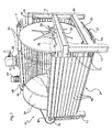
- the apparatus comprises a robust frame indicated as a whole by 10, which is essentially consists of front 12 and rear 14 uprights, front 16 and rear 18 cross members, and side members lower side 20 and upper side 22.
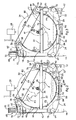
- the conveyor member 24 travels along a route which defines a trough-shaped enclosure 26 ( Figures 2 and 3) constituting a container to receive the objects to treat, such as cork stoppers, whose load or mass is indicated by M in Figures 2 and 3.
- the gauge 26 is open at the top to allow a operator to visually inspect objects at all times subject to processing and possible distribution of a treatment substance on these objects.
- Figures 1 to 3 has been shown by way of example a spray dispenser 28 of a substance of treatment (a lubricant for cork stoppers, by example), which the operator can move according to his judgment along the load M according to the double arrow F1 of the Figure 1 to evenly dose the substance in the charge.
- a substance of treatment a lubricant for cork stoppers, by example
- the path of the conveying member 24 has a shape substantially double U, with an upper branch aisle 30, which defines the trough or container 26, and a lower leg back 32.
- the course of the upper branch 30 of the conveying member 24 has an arcuate shape with a magnitude greater than 180 °.
- This arc shape is defined by a pair of rotary side closing discs 34 which delimit the container 26 on both sides, are located laterally at inside the side edges of the upper branch of the conveying member 24 and are engaged by this branch upper, which causes them to rotate.
- the two discs 34 are carried by a central pin 36 mounted in bearings 38 fixed to the upper beams 22.
- the distance between the discs 34 can be adjusted by sliding along the axis so as to allow the adjustment of the width of the container 26 according to the volume of the load of M objects to be processed.
- Figure 1 the two discs of fence 34 are shown in mixed lines in close positions to obtain a wide container scaled down.
- the upper branch 30 comprises an initial section descending 40 which constitutes a ledge before containment of the load of objects M, an intermediate bottom section 42 with an extent of substantially 180 °, and a section final ascending 44 which ends cantilevered above of the bottom section 42 and along which the objects are trained before falling back to the bottom section 42 according to arrow F3 in FIG. 2.
- the conveying member has a structure similar to that a roller shutter, with a series of slats 46 arranged transversely to the direction of traffic.
- the slats 46 are fixed, by means of plates 48 of preferably at least one chain and preferably three parallel chains 50, including two end chains and one central chain.
- the chains 50 run on respective sprockets which, with the discs 34, define said course substantially double U of the conveying member 24.
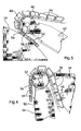
- a group of three driven sprockets 52 ( Figures 2, 3 and 4), wedged on a shaft 54 carried by arm 54 which is part of the frame 10, returns the organ conveyor 24 between the lower branch 32 and the descending section 40 of the upper branch 30;
- a another group of three driven pinions 56 ( Figures 2, 3 and 5), wedged on a shaft 58 carried by arms 60 which make also part of the frame 10, returns the conveying member 24 between the final ascending section 44 of the branch upper 30 and the return branch 32; two others groups of three idler gears 62 and 64 return lower the return branch 32 of the organ carrier 24.
- the section of the return branch 32 returned between the two idler gears 62, 64, indicated by 66 in Figures 1 at 3 and 6, in the preferred embodiment takes a festoon-shaped and acts as a chain tensioner under the effect of the weight of the slats 46.
- a motor-reduction unit 68 with a reversible electric motor 70 and on an output shaft from which is wedged a driving pinion 74 which, through a transmission chain 75 and a driven pinion (not shown), rotates the shaft 58.
- the purpose of the chain drive which in operation normal flows according to arrow F4 in Figure 2, is to not allow the upper branch 30 of the organ conveyor 24 lowers under the weight of the mass M, moving away from the discs 34 and increasing its length to costs of the lower branch back, which would produce a deformation of the trough and compromise its holding capacity.
- the motor 70 is started, the movement of which is transmitted to the conveying member 24 and circulates it in the direction of the arrows F2 in FIG. 2.
- the objects of charge M are shuffled in continuously and during their brewing the operator performs the treatment or treatments required, which he may wish to at all times under his visual surveillance, since the container is not covered.
- the constant radius shape, completely regular and uniform, given by the discs 34 to the container or trough 26, ensures uniform and homogeneous mixing of the objects in any part of their mass.
- the edge initial containment 40 of container 26 has a height as if the conveying member 24 is circulated in the direction F5 opposite to that of normal circulation, the treated objects are dragged up along this edge 40 and project outside, according to arrow F7 of Figure 3, to be collected in a container (not represented).
- the apparatus is preferably provided with a concave plate 82 to collect any dust and fragments descended through slots which are preferably provided for this purpose between the slats 46.
- the plate 82 which is constituted for example by a simple curved sheet of metal or plastic, is located between the bottom section 42 of the upper branch 30 and the bottom section 42 of the lower branch 32 of the conveying member 24.
- the lower beams 20 of the frame 10 are provided with consoles 84 on which tray 82 is all simply placed, which allows it to slide according to arrow F8 in Figure 6 to extract it and rid of discharged R materials.
Landscapes
- Processing Of Solid Wastes (AREA)
- Pretreatment Of Seeds And Plants (AREA)
Abstract
Description
- la figure 1 est une vue en perspective de l'appareil de brassage,
- la figure 2 est une vue de côté schématique et partiellement arrachée de ce même appareil en condition de fonctionnement normal,
- la figure 3 est une vue de côté analogue avec l'appareil en condition de déchargement des produits traités,
- les figures 4 et 5 sont des vues de détail des zones indiquées par les flèches IV et V, respectivement, sur la figure 1, et
- la figure 6 est une vue en perspective de détail qui montre un plateau de réception de poussières et fragments, situé dans la partie inférieure de l'appareil.
Claims (9)
- Appareil de brassage pour le traitement d'objets en vrac, particulièrement de bouchons en liège, du genre comportant un récipient (26) pour accueillir les objets (M) et une éventuelle substance de traitement, et pour les brasser, ce récipient (26) étant délimité par une enceinte (24) animée d'un mouvement continu pour entraíner les objets (M) vers le haut depuis une zone de fond (42) et ensuite les laisser retomber,
caractérisé en ce qu'il comprend un organe transporteur en forme de bande continue motorisée (24) qui circule selon un parcours définissant une enceinte sous forme d'une auge qui constitue le récipient pour accueillir les objets (M) et est ouverte supérieurement pour permettre l'inspection visuelle et le traitement des objets. - Appareil selon la revendication 1, caractérisé en ce que le parcours de l'organe transporteur (24) a une forme sensiblement en double U, avec une branche supérieure d'allée (30) qui délimite le récipient (26) et une branche inférieure de retour (32).
- Appareil selon la revendication 2, caractérisé en ce que le parcours de la branche supérieure (30) de l'organe transporteur a une forme en arc de cercle avec une ampleur supérieure à 180° et comprend, par rapport à son sens de circulation normal (F2), un tronçon initial descendant (40) qui constitue un rebord avant d'endiguement des objets, un tronçon de fond intermédiaire (42) avec une ampleur sensiblement de 180°, et un tronçon final ascendant (44) qui se termine en porte-à-faux au-dessus du tronçon de fond (42) et le long duquel les objets sont entraínés avant de retomber vers le tronçon de fond.
- Appareil selon la revendication 3, caractérisé en ce qu'il comporte un moteur réversible (70) d'entraínement sélectif de l'organe transporteur (24) dans les deux sens de circulation (F2, F5), et en ce que le rebord d'endiguement initial (40) a une hauteur telle que, quand l'organe transporteur (24) est fait circuler dans le sens (F5) contraire à celui de circulation normale, les objets traités son entraínés vers le haut le long dudit rebord d'endiguement (40) et débordent à l'extérieur pour être recueillis.
- Appareil selon la revendication 3 ou 4, caractérisé en ce qu'il comporte une paire de disques de clôture latéraux rotatifs (34) qui délimitent le récipient (26) des deux côtés, sont situés latéralement à l'intérieur des bords latéraux de la branche supérieure (30) de l'organe transporteur et sont engagés par cette branche supérieure pour définir ladite forme en arc de cercle d'ampleur supérieure à 180°.
- Appareil selon la revendication 5, caractérisé en ce que les deux disques (34) sont supportés par un axe central (36) de façon à permettre le réglage de la largeur du récipient (26) moyennant l'ajustement de leur distance par coulissement le long de l'axe (36).
- Appareil selon l'une quelconque des revendications précédentes, caractérisé en ce que l'organe transporteur (24) a une structure semblable à celle d'un volet roulant, avec une série de lattes (46) disposées transversalement par rapport à son sens de circulation.
- Appareil selon la revendication 7, caractérisé en ce qu'il comporte au moins une chaíne sans fin motorisée (50) qui circule selon le parcours de l'organe transporteur (24) et à laquelle les lattes (46) sont fixées.
- Appareil selon la revendication 7 ou 8, caractérisé en ce qu'il comporte un plateau (82) coulissant et amovible, situé entre les tronçons de fond (42, 66) des branches supérieure (30) et inférieure (32) de l'organe transporteur (24) pour recueillir d'éventuelles poussières et fragments tombés à travers les fentes entre les lattes (46).
Applications Claiming Priority (2)
| Application Number | Priority Date | Filing Date | Title |
|---|---|---|---|
| ITTO20021023 ITTO20021023A1 (it) | 2002-11-27 | 2002-11-27 | Apparecchio rimescolatore per il trattamento di oggetti |
| ITTO20021023 | 2002-11-27 |
Publications (2)
| Publication Number | Publication Date |
|---|---|
| EP1424136A2 true EP1424136A2 (fr) | 2004-06-02 |
| EP1424136A3 EP1424136A3 (fr) | 2007-04-04 |
Family
ID=32259984
Family Applications (1)
| Application Number | Title | Priority Date | Filing Date |
|---|---|---|---|
| EP03025976A Withdrawn EP1424136A3 (fr) | 2002-11-27 | 2003-11-13 | Appareil de brassage pour le traitement d'objets en vrac, particulièrement de bouchons en liège |
Country Status (2)
| Country | Link |
|---|---|
| EP (1) | EP1424136A3 (fr) |
| IT (1) | ITTO20021023A1 (fr) |
Family Cites Families (3)
| Publication number | Priority date | Publication date | Assignee | Title |
|---|---|---|---|---|
| US2104055A (en) * | 1933-08-23 | 1938-01-04 | American Foundry Equip Co | Abrading apparatus |
| US2418934A (en) * | 1944-07-11 | 1947-04-15 | American Foundry Equip Co | Cleaning machine |
| US2909012A (en) * | 1957-01-28 | 1959-10-20 | Wheelabrator Corp | Link and flight bar assembly in a blasting machine |
-
2002
- 2002-11-27 IT ITTO20021023 patent/ITTO20021023A1/it unknown
-
2003
- 2003-11-13 EP EP03025976A patent/EP1424136A3/fr not_active Withdrawn
Also Published As
| Publication number | Publication date |
|---|---|
| EP1424136A3 (fr) | 2007-04-04 |
| ITTO20021023A1 (it) | 2004-05-28 |
Similar Documents
| Publication | Publication Date | Title |
|---|---|---|
| EP0192012B1 (fr) | Machines pour enrober uniformément en continu des produits de confiserie | |
| EP0561720B1 (fr) | Procédé et appareil de traitement de particules | |
| CA2066737C (fr) | Machine et procede pour le traitement en continu de surface d'articles de grosseur reduite | |
| EP1406498B1 (fr) | Dispositif pour masser des produits | |
| CH654741A5 (fr) | Appareil pour appliquer un revetement sur des comprimes. | |
| FR2633262A1 (fr) | Procede et dispositif pour transporter successivement des articles de forme plate, tels que bonbons ou analogues | |
| FR2561059A1 (fr) | Dispositif pour epandre une matiere granuleuse et/ou pulverulente | |
| FR2658480A1 (fr) | Appareils pour l'empilage de contenants utilises plus particulierement dans des installations d'emballage au moyen d'une bande matiere thermoretractable. | |
| FR2483744A1 (fr) | Dispositif pour le petrissage circulaire de morceaux de pate | |
| EP1077891B1 (fr) | Mecanisme d'orientation et de distrubution automatique de pieces | |
| EP0132480B1 (fr) | Dispositif pour fabriquer en vrac des produits en sucre ou analogue, par exemple pour la pharmacie homéopathique et produits ainsi obtenus | |
| US1643143A (en) | Apparatus for dusting powdered substances on surfaces | |
| WO2006000703A1 (fr) | Dispositif de traitement de produits alimentaires dans un bain de liquide | |
| EP0688717A1 (fr) | Procédé et dispositif pour le conditionnement de produits tels que les haricots verts | |
| CH664707A5 (fr) | Procede pour le revetement de crayons et installation pour la mise en oeuvre de ce procede. | |
| CH617599A5 (fr) | ||
| EP0125938A1 (fr) | Machine pour effectuer sur des récipients conçus pour des produits pharmaceutiques le dépôt d'un anneau de matière ; ampoules autocassables pourvues d'un tel anneau | |
| FR2609598A1 (fr) | Machine pour le travail de la pate a pain | |
| FR2601559A1 (fr) | Procede pour le transport de pates alimentaires et produits analogues, en particulier a l'interieur d'un sechoir, et appareil pour la mise en oeuvre de ce procede. | |
| FR2660593A1 (fr) | Four de rotomoulage. | |
| FR2539648A1 (fr) | Appareil d'ouverture et de fermeture de l'orifice de sortie d'une machine de preparation | |
| FR2794342A1 (fr) | Procede de fabrication de gateaux a la broche, dispositif permettant de le mettre en oeuvre et pates utilisees | |
| DE92594C (fr) | ||
| BE367287A (fr) | ||
| FR2814092A1 (fr) | Dispositif pour appliquer une substance pulverulente sur des objets, notamment pour saler des fromages |
Legal Events
| Date | Code | Title | Description |
|---|---|---|---|
| PUAI | Public reference made under article 153(3) epc to a published international application that has entered the european phase |
Free format text: ORIGINAL CODE: 0009012 |
|
| AK | Designated contracting states |
Kind code of ref document: A2 Designated state(s): AT BE BG CH CY CZ DE DK EE ES FI FR GB GR HU IE IT LI LU MC NL PT RO SE SI SK TR |
|
| AX | Request for extension of the european patent |
Extension state: AL LT LV MK |
|
| PUAL | Search report despatched |
Free format text: ORIGINAL CODE: 0009013 |
|
| AK | Designated contracting states |
Kind code of ref document: A3 Designated state(s): AT BE BG CH CY CZ DE DK EE ES FI FR GB GR HU IE IT LI LU MC NL PT RO SE SI SK TR |
|
| AX | Request for extension of the european patent |
Extension state: AL LT LV MK |
|
| AKX | Designation fees paid | ||
| REG | Reference to a national code |
Ref country code: DE Ref legal event code: 8566 |
|
| STAA | Information on the status of an ep patent application or granted ep patent |
Free format text: STATUS: THE APPLICATION IS DEEMED TO BE WITHDRAWN |
|
| 18D | Application deemed to be withdrawn |
Effective date: 20071005 |