EP1424204A1 - Bildaufzeichnungsvorrichtung - Google Patents
Bildaufzeichnungsvorrichtung Download PDFInfo
- Publication number
- EP1424204A1 EP1424204A1 EP03027372A EP03027372A EP1424204A1 EP 1424204 A1 EP1424204 A1 EP 1424204A1 EP 03027372 A EP03027372 A EP 03027372A EP 03027372 A EP03027372 A EP 03027372A EP 1424204 A1 EP1424204 A1 EP 1424204A1
- Authority
- EP
- European Patent Office
- Prior art keywords
- ink
- recording apparatus
- image recording
- housing
- solvent
- Prior art date
- Legal status (The legal status is an assumption and is not a legal conclusion. Google has not performed a legal analysis and makes no representation as to the accuracy of the status listed.)
- Withdrawn
Links
- 239000002904 solvent Substances 0.000 claims abstract description 41
- XLYOFNOQVPJJNP-UHFFFAOYSA-N water Chemical compound O XLYOFNOQVPJJNP-UHFFFAOYSA-N 0.000 claims abstract description 35
- 239000003960 organic solvent Substances 0.000 claims abstract description 21
- 239000007788 liquid Substances 0.000 claims description 25
- OKTJSMMVPCPJKN-UHFFFAOYSA-N Carbon Chemical compound [C] OKTJSMMVPCPJKN-UHFFFAOYSA-N 0.000 claims description 10
- VYPSYNLAJGMNEJ-UHFFFAOYSA-N Silicium dioxide Chemical compound O=[Si]=O VYPSYNLAJGMNEJ-UHFFFAOYSA-N 0.000 claims description 7
- 239000000741 silica gel Substances 0.000 claims description 4
- 229910002027 silica gel Inorganic materials 0.000 claims description 4
- 239000002245 particle Substances 0.000 description 55
- 238000007667 floating Methods 0.000 description 27
- 238000001816 cooling Methods 0.000 description 18
- 239000000203 mixture Substances 0.000 description 11
- 230000005684 electric field Effects 0.000 description 8
- 239000000758 substrate Substances 0.000 description 8
- 238000000034 method Methods 0.000 description 7
- 239000003507 refrigerant Substances 0.000 description 6
- 239000011347 resin Substances 0.000 description 6
- 229920005989 resin Polymers 0.000 description 6
- 239000000463 material Substances 0.000 description 5
- 238000001179 sorption measurement Methods 0.000 description 5
- 230000015556 catabolic process Effects 0.000 description 4
- 238000001962 electrophoresis Methods 0.000 description 4
- 239000003595 mist Substances 0.000 description 4
- CNPVJWYWYZMPDS-UHFFFAOYSA-N 2-methyldecane Chemical compound CCCCCCCCC(C)C CNPVJWYWYZMPDS-UHFFFAOYSA-N 0.000 description 3
- SGVYKUFIHHTIFL-UHFFFAOYSA-N 2-methylnonane Chemical compound CCCCCCCC(C)C SGVYKUFIHHTIFL-UHFFFAOYSA-N 0.000 description 3
- YXFVVABEGXRONW-UHFFFAOYSA-N Toluene Chemical compound CC1=CC=CC=C1 YXFVVABEGXRONW-UHFFFAOYSA-N 0.000 description 3
- 238000004040 coloring Methods 0.000 description 3
- 230000007423 decrease Effects 0.000 description 3
- VLKZOEOYAKHREP-UHFFFAOYSA-N n-Hexane Chemical compound CCCCCC VLKZOEOYAKHREP-UHFFFAOYSA-N 0.000 description 3
- 239000003921 oil Substances 0.000 description 3
- 239000000049 pigment Substances 0.000 description 3
- UHOVQNZJYSORNB-UHFFFAOYSA-N Benzene Chemical compound C1=CC=CC=C1 UHOVQNZJYSORNB-UHFFFAOYSA-N 0.000 description 2
- VTYYLEPIZMXCLO-UHFFFAOYSA-L Calcium carbonate Chemical compound [Ca+2].[O-]C([O-])=O VTYYLEPIZMXCLO-UHFFFAOYSA-L 0.000 description 2
- IMNFDUFMRHMDMM-UHFFFAOYSA-N N-Heptane Chemical compound CCCCCCC IMNFDUFMRHMDMM-UHFFFAOYSA-N 0.000 description 2
- XUIMIQQOPSSXEZ-UHFFFAOYSA-N Silicon Chemical compound [Si] XUIMIQQOPSSXEZ-UHFFFAOYSA-N 0.000 description 2
- GWEVSGVZZGPLCZ-UHFFFAOYSA-N Titan oxide Chemical compound O=[Ti]=O GWEVSGVZZGPLCZ-UHFFFAOYSA-N 0.000 description 2
- 238000010521 absorption reaction Methods 0.000 description 2
- PNEYBMLMFCGWSK-UHFFFAOYSA-N aluminium oxide Inorganic materials [O-2].[O-2].[O-2].[Al+3].[Al+3] PNEYBMLMFCGWSK-UHFFFAOYSA-N 0.000 description 2
- 238000005119 centrifugation Methods 0.000 description 2
- 239000003795 chemical substances by application Substances 0.000 description 2
- 239000003086 colorant Substances 0.000 description 2
- DIOQZVSQGTUSAI-UHFFFAOYSA-N decane Chemical compound CCCCCCCCCC DIOQZVSQGTUSAI-UHFFFAOYSA-N 0.000 description 2
- 238000006731 degradation reaction Methods 0.000 description 2
- SNRUBQQJIBEYMU-UHFFFAOYSA-N dodecane Chemical compound CCCCCCCCCCCC SNRUBQQJIBEYMU-UHFFFAOYSA-N 0.000 description 2
- 238000001704 evaporation Methods 0.000 description 2
- 238000007429 general method Methods 0.000 description 2
- 229930195733 hydrocarbon Natural products 0.000 description 2
- 150000002430 hydrocarbons Chemical group 0.000 description 2
- 238000012423 maintenance Methods 0.000 description 2
- 238000012986 modification Methods 0.000 description 2
- 230000004048 modification Effects 0.000 description 2
- BKIMMITUMNQMOS-UHFFFAOYSA-N nonane Chemical compound CCCCCCCCC BKIMMITUMNQMOS-UHFFFAOYSA-N 0.000 description 2
- 230000036961 partial effect Effects 0.000 description 2
- 230000000704 physical effect Effects 0.000 description 2
- BASFCYQUMIYNBI-UHFFFAOYSA-N platinum Chemical compound [Pt] BASFCYQUMIYNBI-UHFFFAOYSA-N 0.000 description 2
- 230000002829 reductive effect Effects 0.000 description 2
- 230000002441 reversible effect Effects 0.000 description 2
- 229910052710 silicon Inorganic materials 0.000 description 2
- 239000010703 silicon Substances 0.000 description 2
- OGIDPMRJRNCKJF-UHFFFAOYSA-N titanium oxide Inorganic materials [Ti]=O OGIDPMRJRNCKJF-UHFFFAOYSA-N 0.000 description 2
- GTJOHISYCKPIMT-UHFFFAOYSA-N 2-methylundecane Chemical compound CCCCCCCCCC(C)C GTJOHISYCKPIMT-UHFFFAOYSA-N 0.000 description 1
- 229920002799 BoPET Polymers 0.000 description 1
- 101100172879 Caenorhabditis elegans sec-5 gene Proteins 0.000 description 1
- 239000004215 Carbon black (E152) Substances 0.000 description 1
- XDTMQSROBMDMFD-UHFFFAOYSA-N Cyclohexane Chemical compound C1CCCCC1 XDTMQSROBMDMFD-UHFFFAOYSA-N 0.000 description 1
- NHTMVDHEPJAVLT-UHFFFAOYSA-N Isooctane Chemical compound CC(C)CC(C)(C)C NHTMVDHEPJAVLT-UHFFFAOYSA-N 0.000 description 1
- 239000005909 Kieselgur Substances 0.000 description 1
- CTQNGGLPUBDAKN-UHFFFAOYSA-N O-Xylene Chemical compound CC1=CC=CC=C1C CTQNGGLPUBDAKN-UHFFFAOYSA-N 0.000 description 1
- 239000002253 acid Substances 0.000 description 1
- 125000002723 alicyclic group Chemical group 0.000 description 1
- 150000001338 aliphatic hydrocarbons Chemical class 0.000 description 1
- XAGFODPZIPBFFR-UHFFFAOYSA-N aluminium Chemical compound [Al] XAGFODPZIPBFFR-UHFFFAOYSA-N 0.000 description 1
- 229910052782 aluminium Inorganic materials 0.000 description 1
- 150000004945 aromatic hydrocarbons Chemical group 0.000 description 1
- 239000000440 bentonite Substances 0.000 description 1
- 229910000278 bentonite Inorganic materials 0.000 description 1
- SVPXDRXYRYOSEX-UHFFFAOYSA-N bentoquatam Chemical compound O.O=[Si]=O.O=[Al]O[Al]=O SVPXDRXYRYOSEX-UHFFFAOYSA-N 0.000 description 1
- 229910000019 calcium carbonate Inorganic materials 0.000 description 1
- 229910052799 carbon Inorganic materials 0.000 description 1
- 239000004927 clay Substances 0.000 description 1
- 238000004140 cleaning Methods 0.000 description 1
- LMGZGXSXHCMSAA-UHFFFAOYSA-N cyclodecane Chemical compound C1CCCCCCCCC1 LMGZGXSXHCMSAA-UHFFFAOYSA-N 0.000 description 1
- WJTCGQSWYFHTAC-UHFFFAOYSA-N cyclooctane Chemical compound C1CCCCCCC1 WJTCGQSWYFHTAC-UHFFFAOYSA-N 0.000 description 1
- 239000004914 cyclooctane Substances 0.000 description 1
- NNBZCPXTIHJBJL-UHFFFAOYSA-N decalin Chemical compound C1CCCC2CCCCC21 NNBZCPXTIHJBJL-UHFFFAOYSA-N 0.000 description 1
- 230000003247 decreasing effect Effects 0.000 description 1
- JVSWJIKNEAIKJW-UHFFFAOYSA-N dimethyl-hexane Natural products CCCCCC(C)C JVSWJIKNEAIKJW-UHFFFAOYSA-N 0.000 description 1
- 230000000694 effects Effects 0.000 description 1
- 238000010292 electrical insulation Methods 0.000 description 1
- 238000005516 engineering process Methods 0.000 description 1
- 229910052736 halogen Inorganic materials 0.000 description 1
- 125000005843 halogen group Chemical group 0.000 description 1
- UQEAIHBTYFGYIE-UHFFFAOYSA-N hexamethyldisiloxane Chemical compound C[Si](C)(C)O[Si](C)(C)C UQEAIHBTYFGYIE-UHFFFAOYSA-N 0.000 description 1
- 238000002347 injection Methods 0.000 description 1
- 239000007924 injection Substances 0.000 description 1
- VKPSKYDESGTTFR-UHFFFAOYSA-N isododecane Natural products CC(C)(C)CC(C)CC(C)(C)C VKPSKYDESGTTFR-UHFFFAOYSA-N 0.000 description 1
- 239000011159 matrix material Substances 0.000 description 1
- 230000005499 meniscus Effects 0.000 description 1
- AUHZEENZYGFFBQ-UHFFFAOYSA-N mesitylene Substances CC1=CC(C)=CC(C)=C1 AUHZEENZYGFFBQ-UHFFFAOYSA-N 0.000 description 1
- 125000001827 mesitylenyl group Chemical group [H]C1=C(C(*)=C(C([H])=C1C([H])([H])[H])C([H])([H])[H])C([H])([H])[H] 0.000 description 1
- VNWKTOKETHGBQD-UHFFFAOYSA-N methane Chemical class C VNWKTOKETHGBQD-UHFFFAOYSA-N 0.000 description 1
- TVMXDCGIABBOFY-UHFFFAOYSA-N octane Chemical compound CCCCCCCC TVMXDCGIABBOFY-UHFFFAOYSA-N 0.000 description 1
- 229910052697 platinum Inorganic materials 0.000 description 1
- 238000007639 printing Methods 0.000 description 1
- 239000000047 product Substances 0.000 description 1
- 239000005871 repellent Substances 0.000 description 1
- 230000002940 repellent Effects 0.000 description 1
- 229910052703 rhodium Inorganic materials 0.000 description 1
- 239000010948 rhodium Substances 0.000 description 1
- MHOVAHRLVXNVSD-UHFFFAOYSA-N rhodium atom Chemical compound [Rh] MHOVAHRLVXNVSD-UHFFFAOYSA-N 0.000 description 1
- 238000007789 sealing Methods 0.000 description 1
- 239000000377 silicon dioxide Substances 0.000 description 1
- 239000007787 solid Substances 0.000 description 1
- 239000000243 solution Substances 0.000 description 1
- 230000006641 stabilisation Effects 0.000 description 1
- 238000011105 stabilization Methods 0.000 description 1
- 230000003068 static effect Effects 0.000 description 1
- 238000006467 substitution reaction Methods 0.000 description 1
- 239000006228 supernatant Substances 0.000 description 1
- 238000012546 transfer Methods 0.000 description 1
- 229910052720 vanadium Inorganic materials 0.000 description 1
- LEONUFNNVUYDNQ-UHFFFAOYSA-N vanadium atom Chemical compound [V] LEONUFNNVUYDNQ-UHFFFAOYSA-N 0.000 description 1
- 239000008096 xylene Substances 0.000 description 1
Images


Classifications
-
- B—PERFORMING OPERATIONS; TRANSPORTING
- B41—PRINTING; LINING MACHINES; TYPEWRITERS; STAMPS
- B41J—TYPEWRITERS; SELECTIVE PRINTING MECHANISMS, i.e. MECHANISMS PRINTING OTHERWISE THAN FROM A FORME; CORRECTION OF TYPOGRAPHICAL ERRORS
- B41J2/00—Typewriters or selective printing mechanisms characterised by the printing or marking process for which they are designed
- B41J2/005—Typewriters or selective printing mechanisms characterised by the printing or marking process for which they are designed characterised by bringing liquid or particles selectively into contact with a printing material
- B41J2/01—Ink jet
- B41J2/17—Ink jet characterised by ink handling
- B41J2/1707—Conditioning of the inside of ink supply circuits, e.g. flushing during start-up or shut-down
-
- B—PERFORMING OPERATIONS; TRANSPORTING
- B41—PRINTING; LINING MACHINES; TYPEWRITERS; STAMPS
- B41J—TYPEWRITERS; SELECTIVE PRINTING MECHANISMS, i.e. MECHANISMS PRINTING OTHERWISE THAN FROM A FORME; CORRECTION OF TYPOGRAPHICAL ERRORS
- B41J2/00—Typewriters or selective printing mechanisms characterised by the printing or marking process for which they are designed
- B41J2/005—Typewriters or selective printing mechanisms characterised by the printing or marking process for which they are designed characterised by bringing liquid or particles selectively into contact with a printing material
- B41J2/01—Ink jet
- B41J2/015—Ink jet characterised by the jet generation process
- B41J2/04—Ink jet characterised by the jet generation process generating single droplets or particles on demand
- B41J2/06—Ink jet characterised by the jet generation process generating single droplets or particles on demand by electric or magnetic field
-
- G—PHYSICS
- G03—PHOTOGRAPHY; CINEMATOGRAPHY; ANALOGOUS TECHNIQUES USING WAVES OTHER THAN OPTICAL WAVES; ELECTROGRAPHY; HOLOGRAPHY
- G03G—ELECTROGRAPHY; ELECTROPHOTOGRAPHY; MAGNETOGRAPHY
- G03G15/00—Apparatus for electrographic processes using a charge pattern
- G03G15/06—Apparatus for electrographic processes using a charge pattern for developing
- G03G15/10—Apparatus for electrographic processes using a charge pattern for developing using a liquid developer
- G03G15/107—Condensing developer fumes
Definitions
- the present invention relates to an image recording apparatus which records an image on an image recording medium.
- Color ink or black ink is widely used in an electrophotography apparatus or an ink jet type image recording apparatus, and organic solvent based ink is often used.
- organic solvent based ink ink for ink jet type image recording apparatus, electrophotography liquid developer or the like is used.
- Organic solvent within ink is apt to evaporate, within a housing of an apparatus, to become vapor (steam). Therefore, a recovering device for recovering vapor of organic solvent is often provided within a housing of an image recording apparatus.
- conventional technology mainly, ink for ink jet type image recording apparatus, will be explained.
- recovering means for recovering solvent vapor is provided at a transfer-type inkjet type printer.
- the solvent vapor which is generated when the solvent is removed from ink on a medium transfer body, is recovered, and the recovered solvent is discarded.
- JP-A Japanese Patent Application Laid-Open (JP-A) No. 11-320856
- ink solvent evaporating accelerating means is provided at a printer, solvent vapor generated from a recording paper is recovered, and the recovered solvent is recycled.
- Recovering of the solvent vapor is carried out by absorbing it to an alumina or a silica, trapping it to a container in which liquid for cooling is accommodated, or the like.
- efficiency of recovering of the solvent vapor becomes low.
- problems such as scaling up of the recovering apparatus, increasing of electric power consumption of the recovering apparatus, lowering of maintenance ability, and the like.
- the present invention provides an image recording apparatus which can recover vapor of solvent efficiently and is miniaturized.
- a first aspect of the present invention is an image recording apparatus which records an image on a recording medium, the image recording apparatus comprising in a housing thereof a water vapor removing section which removes water vapor, and a solvent recovering section which recovers vapor of organic solvent, which evaporates within the housing.
- the vapor of organic solvent is vapor evaporated from a recording liquid for recording the image on the recording medium.
- the water vapor removing section is provided at an inlet port which takes in air from outside of the housing into the inside of the housing.
- the solvent recovering section is provided at an outlet port which exhausts air from the inside of the housing to the outside of the housing.
- the housing is in a substantially sealed state except for the inlet port and the outlet port.
- an activated carbon filter is used as the water vapor removing section.
- a silica gel filter is used as the water vapor removing section.
- the image recording apparatus is an ink jet type image recording apparatus.
- a ninth aspect of the present invention is an image recording apparatus which records an image on a recording medium, the image recording apparatus comprising in a housing thereof, a water vapor removing section which removes water vapor, and a solvent recovering section which recovers vapor of organic solvent, which evaporates within the housing, wherein the water vapor removing section is provided at an inlet port which takes in air from outside of the housing into the inside of the housing.
- the organic solvent is mainly volatile solvent in the present invention.
- the water vapor is mixed to the vapor of organic solvent evaporating within the housing. Because the image recording apparatus comprises in the housing thereof the water vapor removing section which removes water vapor, the amount of this water vapor can be reduced to a large extent. Accordingly, effects such as that ability of the removing solvent of the solvent recovering section is improved; the solvent recovering section is stably operated (that is, maintenance performance is improved); the recovered organic solvent is reused, and the like are obtained. Further, it can be realized that the image recording apparatus is miniaturized.
- the humidity within the housing is lowered considerably by the water vapor removing section, in a case in which a paper sheet is used as the image recording medium, waving of the paper sheet is prevented and dimension stability of the paper sheet is improved. Therefore, it can be prevented that jam occurs and it can be archived that high quality image is recorded.
- the recording medium is conveyed by used of electrostatic adsorption manner, adsorption force can be stabilized due to charging potential stabilization of the medium.
- electrostatic force applied to a ejected liquid droplet is maintained constantly because the charging potential is stabilized. Therefore, fly speed of the liquid droplet can be uniformed, and further high quality image can be obtained.
- an adsorption filter for example, an activated carbon filter
- a cooling element for example, Peltier element
- the vapor of organic solvent is often the vapor evaporated from the recording liquid for recording the image on the recording medium. Accordingly, the amount of use of the organic solvent can be decreased drastically by recovering the solvent by the above mentioned solvent recovering section in a state in which the recovered organic solvent can be reused.
- the water vapor in the air taken in the system of the image recording apparatus is removed by the water vapor removing section.
- water vapor removing section is provided at the inlet port which inhales air outside of the housing to the inside of the housing. In this case, the humidity in the housing can be efficiently lowered because the all of air taken in the housing passes through the water vapor removing section.
- an electrophotography apparatus As the above mentioned image recording apparatus, an electrophotography apparatus, an ink jet type image recording apparatus, or the like can used.
- liquid developer of organic solvent type is used in the electrophotography apparatus. Accordingly, the vapor of solvent within the housing can be efficiently recovered, and an electrophotography image of high quality can be obtained.
- the ink jet type image recording apparatus 22 which is preferably used in the present invention is an image recording apparatus in which density of ink in the vicinity of an ink ejection portion is increased by electrophoresis of charged particles in an ink channel, and an ink droplet whose density is increased as such is ejected by electrostatic attraction force caused by mainly a recording medium or a counter electrode which is disposed at a back side of the recording medium.
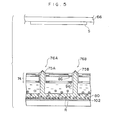
- An ink circulation system 24, a head unit 28 and a driver 32 are provided in a housing 28 of the image recording apparatus 22.
- the ink circulation system 24 circulates an ink.
- the head unit 28 has four heads (for four colors of Y, M, C and K, respectively) each of which ejects the corresponding ink provided from the ink circulation system 24.
- the driver is connected to the head unit 28.
- an air inlet (a suction port) 38 through which air at the outside of the housing 26 is taken in the housing 26 and an air outlet (an exhaust port) 40 through which air in the inside of the housing 26 is exhausted to the outside of the housing 26 are arranged.
- An exhausting section 42 is provided at the air outlet 40 at the inside of the housing 26. The exhausting section 42 exhausts an air within the housing 26 together with recovers solvent vapor contained in this air.
- one of means of the following well known methods (1) - (4) or the like can be singly used, or combination of means of the following well known means (1) - (4) or the like can be used.
- An organic solvent based ink is used in the image recording apparatus 22.
- the solvent vapor is vapor which evaporates from this ink.
- the housing 26 is in a state of sealing as far as possible without the air inlet 38 and the air outlet 40. That is, the housing 26 is substantially in a closed state. Therefore, due to exhaust from the exhausting section 42, air at the outside of the image recording apparatus 22 is sucked into the housing 22 only through the air inlet 38. Further, A water vapor removing section 44 is provided at the air inlet 38 at the inside of the housing 26. All air, which is sucked from the air inlet 38, at the outside the image recording apparatus 22 passes through the water vapor removing section 44.
- a recording sheet S is held on a conveying member 66 in the image recording apparatus 22 such that the recording sheet S can be moved in a direction P.
- a head 20 is disposed below a position, at which the recording sheet S is in a substantially horizontal state, by a predetermined distance.
- the recording sheet S is charged negative (for example, -1.5 kV) by a Scorotron charger 64, therefore, the recording sheet S is electrostatically held at a lower side of the belt shape conveying member 66.
- a electrical insulating layer (not shown in the drawings) is provided at an outer side surface (in Fig. 3, at a lower side), on which the recording sheet S contacts, of the conveying member 66.
- the head 20 has an ink channel 72, a substrate 74 and a plurality of ejection portions 76.
- the ink flows in one direction Q in the ink channel 72.
- the substrate 74 forms an upper wall of the ink channel 72.
- Each ejection portion 76 ejects the ink droplet toward the recording sheet S.
- An ink guide 78 is provided at each of the ink ejection portions 76.
- the ink guide 78 guides an ink droplet G, which flies from the ink channel 72, toward the recording sheet S.
- An opening 75 through which each ink guide 78 is inserted is formed in the substrate 74.
- a gap d between the ink guide 78 and the recording sheet S is often within a range between about 200 ⁇ m and about 1000 ⁇ m.
- the ink guide 78 is fixed to a supporting bar member 80 at a lower end of the ink guide 78.
- the substrate 74 has an insulating layer 84, a first ejection electrode 86, an insulating layer 88, a guard electrode 90, an insulating layer 92, a second ejection electrode 96 and an insulating layer 98.
- the insulating layer 84 separates two ejection electrodes by a predetermined distance to electrically isolate them from each other.
- the first ejection electrode 86 is formed at an upper side of the insulating layer 84.
- the insulating layer 88 covers the first ejection electrode 86.
- the guard electrode 90 is formed at an upper side of the insulating layer 88.
- the insulating layer 92 covers the guard electrode 90.
- the second ejection electrode 96 is formed at a lower side of the insulating layer 84.
- the insulating layer 98 covers the second ejection electrode 96.
- the guard electrode 90 is provided to prevent that electric field of the adjacent ejection portion is affected by voltage applied to the first ejection electrode 86
- a floating conductive plate 102 is provided at the head 20.
- the floating conductive plate 102 forms a bottom surface of the ink channel 72.
- An ink particle (a charged particle) R charged positive in the ink channel 72 is migrated (so as to perform electrophoresis) upward (that is, toward the side of the recording sheet S) due to the floating conductive plate 102, by induced voltage generated steadily by ejection voltage in pulse state applied to the first ejection electrode 86 and the second ejection electrode 96.
- a coat layer 104 (Fig. 7) which has electrical insulating characteristic is formed on a surface of the floating conductive plate 102, therefore, it is prevented that physical properties and/or component of the ink become unstable by injection of electric charge into the ink or the like.
- electrical resistance of the coat layer which has electrical insulating characteristic is equal to or more than 10 12 ⁇ • cm. It is further preferable that the electrical resistance is equal to or more than 10 13 ⁇ • cm. Further, it is preferable that the coat layer which has electrical insulating characteristic is anticorrosive against the ink, as the result, it is prevented that the floating conductive plate 102 is corroded by the ink. Further, the floating conductive plate 102 is covered by an insulating member 106 at the bottom side of the floating conductive plate 102. Accordingly, the floating conductive plate 102 is completely in a state of electrically floating due to the structures mentioned above.
- At least one floating conductive plate 102 is provided every one head. That is, in a case in which four heads for C, M, Y and K are provided at the image recording apparatus, each of the heads has at least one floating conductive plate, and there is no case in which a common floating conductive plate is used for the head for C and the head for M.
- Colored charged particles whose diameter are about 0.1 ⁇ m - 5 ⁇ m are dispersed in carrier liquid, and it is used as the ink provided in the ink channel 72.
- the carrier liquid is dielectric liquid having high specific resistance (resistivity) of 10 10 ⁇ • cm or more. If the carrier liquid having low specific resistance is used, the electric charge is injected into the carrier liquid itself by voltage applied by the ejection electrode, as a result, the carrier liquid is charged. Therefore, in this case, it is impossible to increase density of the charged particles (charged ink particles), that is, concentration of the charged particles does not occur. Further, use of the carrier liquid of low specific resistance is not appropriate to the present embodiment because it is concerned that the carrier liquid of low specific resistance causes electrical breakdown between the adjacent recording electrodes.
- specific dielectric constant of the dielectric liquid is equal to or less than 5, more preferably, equal to or less than 4, further preferably, equal to or less than 3.5. Electric field is applied to the charged particles in the dielectric liquid effectively by setting the specific dielectric constant at a value within the range mentioned above. As a result, the electrophoresis becomes likely to occur.
- straight chain or branch aliphatic hydrocarbons, alicyclic hydrocarbon, aromatic hydrocarbon, halogen substitution product of these hydrocarbons and the like are preferable as the dielectric liquid used in the present invention.
- one of the following is singly used, or mixture of some of the following is used: hexane, heptane, octane, isooctane, decane, isodecane, dekalin, nonane, dodecane, isododecane, cyclohexane, cyclooctane, cyclodecane, benzen, toluene, xylene, mesitylene, Isopar C, Isopar E, Isopar G, Isopar H, Isopar L (Isopar (trade name): Exxon Corporation), Shellsol 70, Shellsol 71 (Shellsol (trade name) Shell Oil Corporation), Amusco OMS Amusco 460 (Amusco (trade name
- coloring material itself as dispersed particle is dispersed in the dielectric liquid, or it is possible that the coloring material is contained in dispersed resin particle for improvement of fixing.
- the coloring material in a case in which the coloring material is contained in dispersed resin particle, in a case of pigment or the like, it is a general method in which the pigment is coated by resin material of the dispersed resin particles to make a resin coated particle.
- dispersed resin particle is dyed (colored) to generate color particle.
- any one of ink composition for ink-jet, ink composition for printing, or the pigment or the dye which is used in liquid developer for electrophotography can be used. It is preferable that these color particles are contained within a range of 0.5 - 30 percentage by weight with respect to the total of the ink. It is further preferable that the range is between 1.5 - 25 percentage by weight, more preferably, the range is between 3.0 - 20 percentage by weight.
- an average particle diameter of the color particles dispersed in the dielectric solvent of the present invention is within a range of 0.1 ⁇ m - 5 ⁇ m, more preferably, 0.2 ⁇ m - 1.5 ⁇ m, further preferably, 0.4 ⁇ m - 1.0 ⁇ m.
- the particle diameter is measured by CAPA-500 (trade name) manufactured by HORIBA, Ltd..
- viscosity is within a range of 0.5 mPa • sec - 5 mPa • sec, more preferably, 0.6 mPa • sec - 3.0 mPa • sec, further preferably, 0.7 mPa • sec - 2.0 mPa • sec.
- the color particle has charge, and various charge control agent used in the liquid developer for electrophotography can be used according to demand. In this case, it is preferable that charge amount is within a range of 5 ⁇ C/g - 200 ⁇ C/g, more preferably, 10 ⁇ C/g - 150 ⁇ C/g, further preferably, 15 ⁇ C/g - 100 ⁇ C/g.
- the distribution factor P defined below is equal to or more than 50 %, more preferably, equal to or more than 60 %, further preferably, equal to or more than 70 %.
- P 100 ⁇ ( ⁇ 1 - ⁇ 2) / ⁇ 1
- ⁇ 1 is electric conductivity of the ink composition
- ⁇ 2 is electric conductivity of supernatant liquid which is obtained by the ink composition is subject to centrifugation by a centrifugal separator.
- Values of the electric conductivity are measured, by use of a LCR meter (AG-4311 manufactured by Ando Electric Co., Ltd.) and an electrode for liquid (LP-05 type manufactured by Kawaguchi Electric Works Co., Ltd.), in a condition in which applied voltage is 5 V and frequency is 1 kHz.
- centrifugation is carried out in 30 minutes by use of a small high speed cooling centrifugal separator (SRX-201 type manufactured by TOMY SEIKO CO., LTD.) in a condition in which rotation speed is 14500 rpm and temperature is 23°C.
- SRX-201 type manufactured by TOMY SEIKO CO., LTD.
- the electrophoresis of the charged particles becomes likely to occur. Further, the concentration of the charged particles becomes likely to occur.
- the electric conductivity of the ink composition ⁇ 1 is within a range of 100 pS/cm - 3000 pS/cm, more preferably, 150 pS/cm - 2500 pS/cm, further preferably, 200 pS/cm - 2000 pS/cm.
- surface tension of the ink composition is within a range of 15 mN/m - 50 mN/m, more preferably, 15.5 mN/m - 45 mN/m, further preferably, 16 mN/m - 40 mN/m.
- a predetermined positive voltage for example, +100 V
- a predetermined positive voltage for example, +100 V
- first ejection electrode 86 and the second ejection electrode 96 are applied to the first ejection electrode 86 and the second ejection electrode 96 such that flight-electric field is formed between the first ejection electrode 86 and the second ejection electrode 96 and the recording sheet S, the flight electric field being an electric field by which the positive charged particles R within the ink droplet G, which is guided by means of the ink guide 78 and flies from the opening 75, is attracted to and arrive at the recording sheet S.
- electric potential difference of about 1 kV - 3 kV is formed in a case in which the gap d is 500 ⁇ m.
- the ink droplet G whose charged particle density is made high is ejected from the opening 75.
- the initial charged particle density is within a range of 3 % - 15 %
- the charged particle density of the ink droplet G becomes equal to or more than 30 %.
- the electric field between the first ejection electrode 86 and the second ejection electrode 96 is adjusted such that the ink droplet G is ejected only when the pulse voltage is applied to both the first ejection electrode 86 and the second ejection electrode 96.
- matrix driving becomes possible, therefore, the number of drivers can be reduced.
- attraction electric field toward the recording medium is set within a range of equal to or less than 1.5 ⁇ 10 7 V/m, preferably, equal to or less than 1.0 ⁇ 10 7 V/m in a state in which the ink droplet G is not ejected, and the electric field toward the recording medium is set within a range of equal to or more than 2.0 ⁇ 10 7 V/m, preferably, equal to or more than 2.5 ⁇ 10 7 V/m in a state in which the ink droplet G is ejected.
- the pulse voltage of +600 V is applied to both the first ejection electrode 86 and the second ejection electrode 96.
- Pulse width is often within a range from several tens ⁇ s to several hundreds ⁇ s.
- a diameter of a dot recorded on the recording sheet depends on the pulse voltage and application time of the pulse voltage and can be adjusted.
- the ink droplet G is guided by means of the ink guide 78, flies from the opening 75 and is adhered to the recording sheet S. Together with this, the positive induced voltage is generated in the floating conductive plate 102 due to the positive voltage applied to the first ejection electrode 86 and the second ejection electrode 96. Even in the case in which the voltage applied to the first ejection electrode 86 and the second ejection electrode 96 is pulse voltage, the induced voltage is substantially constant. (For example, in a case in which the pulse voltage in which 600 V and 0 V repeat alternately is applied to the first ejection electrode 86 and the second ejection electrode 96, the positive voltage of 300 V is generated in the floating conductive plate 102 constantly.
- the electric potential difference of several hundreds V is set with respect to thickness in vertical direction of the ink channel 72 of several ⁇ m. Accordingly, due to the positive electric potential of the floating conductive plate 102, the charged particle R which is charged positive in the ink channel 72 receives force which moves the charged particle R upward, therefore, the density of the charged particles R in the vicinity of the substrate becomes high. At this time, even though the ink is located in the opening 75, it may occur that the charged particle R in the opening is constrained by surface tension of the ink, as a result, the density of the charged particles R becomes high. That is, the concentration is further proceeded due to choice of voltage application condition and the physical properties of the ink.
- a switch (not shown in the drawings), which enables to switch between a state of floating and a state of application of negative voltage for self cleaning, is connected to the floating conductive plate 102, to set the floating conductive plate 102 in electrical floating state at a time of operation of the image recording apparatus 22 and to apply negative voltage to the floating conductive plate 102 at a time of stop of operation of the image recording apparatus 22.
- the floating conductive plate 102 is electrical floating state, that is, electrical insulation state.
- the density of the charged particles R in the vicinity of the substrate 74 is high in a case in which the ejection portions in use (that is, the ejection electrodes in use) are many in number, and the density of the charged particles R in the vicinity of the substrate 74 is low in a case in which the ejection portions in use are a little in number. Namely, the density is automatically adjusted. Accordingly, it is prevented that the openings of the ejection portions not in use are clogged even in a case in which the ejection portions in use are small in number.
- the ink particle may have the reverse polarity (that is, the ink particle is a negative charged particle).
- the recording medium has also the reverse polarity.
- the positive charged particle is used, the positive voltage is applied to the ejection electrode, and the recording medium is negatively charged.
- polarity of the charged particle is the same as that of the voltage applied to the ejection electrode when the ink is ejected, and electro static charge polarity of the recording medium is the same as the polarity of the charged particle, or the recording medium is not charged.
- polarity of the charged particle is inverse to that of the voltage applied to the ejection electrode when the ink is ejected and charge polarity of the recording medium.
- an electrostatic force is not applied to the whole of the ink but is applied to the charged particles (charged ink particles) R, which are solid bodies dispersed in the carrier liquid, an image can be recorded on various recording medium such as a plain paper, a nonabsorbable PET film and the like. Further, loss of definition or blur on the recording medium does not occur. Therefore, a high quality image can be formed on the various image recording medium.
- structure in which a shield electrode 108 is provided within the insulating layer 98 and the electric potential which moves the charged particle R toward the recording sheet side can be applied to the floating conductive plate 102, can be applied to the image recording apparatus.
- the charged particle R receives repulsive (repellent) force from the ejection portion 76 by the electric potential due to the first ejection electrode 86 and the second ejection electrode 96.
- the exhausting section 42 is provided at the air outlet 40, and the water vapor removing section 44 is provided at the air inlet 38 at the inside thereof. Because all air outside the image recording apparatus 22, which is sucked from the air inlet 38, pass through the water vapor removing section 44, the humidity within the housing 26 can be lowered drastically. As a result, amount of water vapor recovered by the exhausting section 42 decreases drastically. Therefore, the electric power consumed by the exhausting section 42 decreases very much, that is, energy saving is archived. Further, the exhausting section 42 can be miniaturized. Moreover, waving and jamming of the recording sheet S can be prevented, and a high quality image can be recorded on the recording sheet S.
- Heads of 1200dpi/1200ch are installed in the image recording apparatus 22 shown in Fig. 1.
- Each of the heads correspond to respective colors (one head corresponds to none color).
- an activated carbon filter is used as the water vapor removing section.
- a cooling and concentration device of the solvent recovering device a well known device comprising a cooling device and a mist separator is used.
- the cooling device comprises a plurality of cooling fins made of aluminum and a refrigerant pipe passing through the cooling fins.
- a refrigerant delivery pipe and a refrigerant return pipe from a cooler unit are connected to the refrigerant pipe for circulation of refrigerant. Temperature of the refrigerant is -10 °C.
- the mist separator disposed at downstream side of the cooling device is formed from a stainless mesh member.
- the mist separator recovers solvent mist, which is atomized within the cooling device, by liquefcation manner. Further, it is possible that gas obtained by solvent-removing by the cooling and concentration device is returned to the device inside such that the gas is circulated in this cooling and concentration device in a plurality of times. The recovered solvent is recycled as an ink diluted solution. In a case in which ink containing solvent Isopar G is used, solvent contents of the exhaust gas (gas exhausted outside the device) is 23 ppm, and it does not smell. Further, degradation of efficiency by icing of moisture contained in air within the cooling and concentration element does not occur.
- a silica gel is used as the water vapor removing section. Further, the structure of the solvent recovering device is altered. Other structures as those of the Example 1 are the same. At the solvent recovering device, temperature of the cooling device is -5 °C, and an absorption filter is further provided at the downstream side.
- the absorption filter has a structure in which honeycomb layer formed of an activated carbon fiber (height: 10 cm, length: 30 cm, thickness: 6 cm) is attached to a cartridge.
- solvent contents of the exhaust gas is 18 ppm, and at the vicinity of the gas exhaust portion, it is not soiled and sticky at all. Further, degradation of efficiency by icing of moisture contained in air within the cooling and concentration element does not occur.
- the image recording apparatus has the structure mentioned above, the image recording apparatus which can recover vapor of organic solvent efficiently and is miniaturized can be realized.
Landscapes
- Physics & Mathematics (AREA)
- General Physics & Mathematics (AREA)
- Ink Jet (AREA)
Applications Claiming Priority (2)
| Application Number | Priority Date | Filing Date | Title |
|---|---|---|---|
| JP2002348615 | 2002-11-29 | ||
| JP2002348615A JP2004181672A (ja) | 2002-11-29 | 2002-11-29 | 画像記録装置 |
Publications (1)
| Publication Number | Publication Date |
|---|---|
| EP1424204A1 true EP1424204A1 (de) | 2004-06-02 |
Family
ID=32290505
Family Applications (1)
| Application Number | Title | Priority Date | Filing Date |
|---|---|---|---|
| EP03027372A Withdrawn EP1424204A1 (de) | 2002-11-29 | 2003-11-27 | Bildaufzeichnungsvorrichtung |
Country Status (3)
| Country | Link |
|---|---|
| US (1) | US20040104963A1 (de) |
| EP (1) | EP1424204A1 (de) |
| JP (1) | JP2004181672A (de) |
Cited By (4)
| Publication number | Priority date | Publication date | Assignee | Title |
|---|---|---|---|---|
| EP1743772A2 (de) | 2005-07-12 | 2007-01-17 | Fuji Photo Film Co., Ltd. | Tintenstrahlkopf, Tintenstrahlaufzeichnungsgerät und Vorrichtung zur Herstellung einer Druckplatte |
| EP1623832A3 (de) * | 2004-08-02 | 2007-08-15 | FUJIFILM Corporation | Flüssigkeitsausstosskopf und Verfahren zur Herstellung desselben |
| US7275812B2 (en) | 2003-01-29 | 2007-10-02 | Fujifilm Corporation | Ink jet head and recording apparatus using the same |
| WO2013182393A1 (en) * | 2012-06-08 | 2013-12-12 | Oce-Technologies B.V. | Droplet ejection device |
Families Citing this family (6)
| Publication number | Priority date | Publication date | Assignee | Title |
|---|---|---|---|---|
| JP2006082287A (ja) * | 2004-09-14 | 2006-03-30 | Fuji Xerox Co Ltd | インクジェット記録装置 |
| JP5178423B2 (ja) * | 2008-09-16 | 2013-04-10 | 富士フイルム株式会社 | 画像記録方法 |
| JP5397145B2 (ja) * | 2009-10-15 | 2014-01-22 | コニカミノルタ株式会社 | インクジェットプリンタ |
| JP5750942B2 (ja) * | 2011-03-07 | 2015-07-22 | セイコーエプソン株式会社 | 液体噴射装置 |
| JP6249157B2 (ja) | 2013-10-11 | 2017-12-20 | セイコーエプソン株式会社 | 液体噴射装置 |
| JP7081244B2 (ja) * | 2018-03-19 | 2022-06-07 | 株式会社リコー | 液体回収装置、液体付着装置、液体回収装置の液体回収方法、及び液体回収プログラム |
Citations (3)
| Publication number | Priority date | Publication date | Assignee | Title |
|---|---|---|---|---|
| US4387638A (en) * | 1981-02-26 | 1983-06-14 | Siemens Aktiengesellschaft | Device for removing water from the solvent recovery system of a fast printer |
| US5012737A (en) * | 1988-09-22 | 1991-05-07 | Mitsubishi Jukogyo Kabushiki Kaisha | Ink feeder with moisture removal |
| US5708938A (en) * | 1994-12-14 | 1998-01-13 | Ricoh Company, Ltd. | Wet process image forming apparatus and carrier vapor collecting device therefor |
Family Cites Families (23)
| Publication number | Priority date | Publication date | Assignee | Title |
|---|---|---|---|---|
| BE533439A (de) * | 1953-11-18 | |||
| DE2226309C3 (de) * | 1971-06-03 | 1980-09-11 | Canon K.K., Tokio | Vorrichtung zur Rückgewinnung von Entwickler-Trägerflüssigkeit |
| US3768232A (en) * | 1972-01-06 | 1973-10-30 | Republic Corp | Solvent recovery system |
| US3854224A (en) * | 1972-06-16 | 1974-12-17 | Canon Kk | Device for heating and drying copy mediums |
| US3997977A (en) * | 1972-12-26 | 1976-12-21 | Canon Kabushiki Kaisha | Developing liquid recovery device in a copying machine |
| US4254339A (en) * | 1977-06-29 | 1981-03-03 | Yanagimoto Seisakusho Co. Ltd. | Method for the fluorimetric quantitative determination of SO2 in gases and apparatus therefor |
| US4343769A (en) * | 1980-08-11 | 1982-08-10 | W. R. Grace & Co. | Catalytic solvent vapor incinerating apparatus |
| DE3045485A1 (de) * | 1980-12-03 | 1982-07-08 | Hoechst Ag, 6000 Frankfurt | Verfahren und vorrichtung zum thermischen fixieren von tonerbildern |
| US4708775A (en) * | 1985-07-08 | 1987-11-24 | Anachemia Solvents Limited | Disposal of wastes with solvent recovery |
| US4687319A (en) * | 1986-06-18 | 1987-08-18 | Xerox Corporation | Liquid carrier reclaiming apparatus |
| US4733272A (en) * | 1986-07-17 | 1988-03-22 | Xerox Corporation | Filter regeneration in an electrophotographic printing machine |
| JPH0732841B2 (ja) * | 1991-02-21 | 1995-04-12 | 豊田化学工業株式会社 | 有機溶剤の廃液処理システム |
| US5477256A (en) * | 1992-03-27 | 1995-12-19 | Scitex Digital Printing, Inc. | Ink mist filter |
| DE4233531A1 (de) * | 1992-10-06 | 1994-04-07 | Hoechst Ag | Perfluorisohexen als Kühl- und Isoliermedium |
| DE59402050D1 (de) * | 1993-11-18 | 1997-04-17 | Sebald U E | Verfahren und Anlage zum Entfernen von Lösemitteldämpfen aus Abluft |
| KR100234281B1 (ko) * | 1997-08-27 | 1999-12-15 | 윤종용 | 습식 전자사진방식 인쇄기의 액체 캐리어 회수장치 |
| JP3390387B2 (ja) * | 1999-11-17 | 2003-03-24 | 米沢日本電気株式会社 | 現像液媒体の蒸気回収装置および方法 |
| JP2001166596A (ja) * | 1999-12-06 | 2001-06-22 | Nec Niigata Ltd | 画像形成装置及び画像品質管理方法 |
| JP2001228715A (ja) * | 2000-02-18 | 2001-08-24 | Nec Yonezawa Ltd | 湿式電子写真画像形成装置のキャリア回収機構およびキャリア回収方法 |
| JP3577458B2 (ja) * | 2000-10-31 | 2004-10-13 | 株式会社東芝 | 湿式電子写真装置 |
| US6693295B2 (en) * | 2000-12-25 | 2004-02-17 | Fuji Photo Film Co., Ltd. | Indole derivative, material for light-emitting device and light-emitting device using the same |
| US6643220B2 (en) * | 2002-03-21 | 2003-11-04 | Hewlett-Packard Development Company, L.P. | Vapor handling in printing |
| KR100467607B1 (ko) * | 2002-08-22 | 2005-01-24 | 삼성전자주식회사 | 캐리어증기 희석장치를 갖는 습식인쇄기의 정착기 및 이를채용한 습식인쇄기 |
-
2002
- 2002-11-29 JP JP2002348615A patent/JP2004181672A/ja active Pending
-
2003
- 2003-11-26 US US10/721,262 patent/US20040104963A1/en not_active Abandoned
- 2003-11-27 EP EP03027372A patent/EP1424204A1/de not_active Withdrawn
Patent Citations (3)
| Publication number | Priority date | Publication date | Assignee | Title |
|---|---|---|---|---|
| US4387638A (en) * | 1981-02-26 | 1983-06-14 | Siemens Aktiengesellschaft | Device for removing water from the solvent recovery system of a fast printer |
| US5012737A (en) * | 1988-09-22 | 1991-05-07 | Mitsubishi Jukogyo Kabushiki Kaisha | Ink feeder with moisture removal |
| US5708938A (en) * | 1994-12-14 | 1998-01-13 | Ricoh Company, Ltd. | Wet process image forming apparatus and carrier vapor collecting device therefor |
Non-Patent Citations (1)
| Title |
|---|
| DRISCOLL ET AL: "Evaporation recovery system", IBM TECHNICAL DISCLOSURE BULLETIN, IBM CORP. NEW YORK, US, vol. 25, no. 3A, 1 August 1982 (1982-08-01), pages 946 - 947, XP002081594, ISSN: 0018-8689 * |
Cited By (8)
| Publication number | Priority date | Publication date | Assignee | Title |
|---|---|---|---|---|
| US7275812B2 (en) | 2003-01-29 | 2007-10-02 | Fujifilm Corporation | Ink jet head and recording apparatus using the same |
| EP1442886B1 (de) * | 2003-01-29 | 2010-03-10 | FUJIFILM Corporation | Elektrostatischer Tintenstrahlkopf und damit ausgestattetes Aufzeichnungsgerät |
| EP1623832A3 (de) * | 2004-08-02 | 2007-08-15 | FUJIFILM Corporation | Flüssigkeitsausstosskopf und Verfahren zur Herstellung desselben |
| US7681995B2 (en) | 2004-08-02 | 2010-03-23 | Fujifilm Corporation | Liquid ejection head and method of manufacturing the same |
| EP1743772A2 (de) | 2005-07-12 | 2007-01-17 | Fuji Photo Film Co., Ltd. | Tintenstrahlkopf, Tintenstrahlaufzeichnungsgerät und Vorrichtung zur Herstellung einer Druckplatte |
| EP1743772A3 (de) * | 2005-07-12 | 2009-07-22 | FUJIFILM Corporation | Tintenstrahlkopf, Tintenstrahlaufzeichnungsgerät und Vorrichtung zur Herstellung einer Druckplatte |
| WO2013182393A1 (en) * | 2012-06-08 | 2013-12-12 | Oce-Technologies B.V. | Droplet ejection device |
| US9216577B2 (en) | 2012-06-08 | 2015-12-22 | Oce-Technologies B.V. | Droplet ejection device |
Also Published As
| Publication number | Publication date |
|---|---|
| JP2004181672A (ja) | 2004-07-02 |
| US20040104963A1 (en) | 2004-06-03 |
Similar Documents
| Publication | Publication Date | Title |
|---|---|---|
| EP1375167B1 (de) | Tintenstrahlaufzeichnungsgerät und -aufzeichnungsverfahren | |
| JP3744787B2 (ja) | 強磁性流体インクジェットプリントヘッドシーリングおよびスピッティングシステム | |
| EP1424204A1 (de) | Bildaufzeichnungsvorrichtung | |
| JP2007261204A (ja) | 液体吐出ヘッド及びこれを備えた画像形成装置 | |
| CN1519113B (zh) | 喷墨头和使用该喷墨头的记录装置 | |
| US7651193B2 (en) | Ink jet recording apparatus | |
| JP2001315321A (ja) | インクジェット式印刷方法及び印刷装置 | |
| JP2006015637A (ja) | インクジェット記録装置 | |
| US7300139B2 (en) | Ink jet recording apparatus using charged fine particle-containing ink | |
| EP1518680B1 (de) | Tintenstrahlkopf und Tintenstrahlaufzeichnungsgerät | |
| EP1645423A2 (de) | Tintenstrahlaufzeichnungsgerät und Verfahren | |
| EP1574339A2 (de) | Tintenstrahlkopf und Tintenstrahlaufzeichnungsgerät | |
| EP1552927B1 (de) | Tintenstrahlkopf und Tintenstrahlaufzeichnungsgerät | |
| JP3313603B2 (ja) | インクジェット記録装置 | |
| EP1495868B1 (de) | Tintenstrahldruckkopf und Tintenstrahlaufzeichnungsgerät | |
| JP2004181673A (ja) | インクジェットヘッド及び画像記録装置 | |
| EP1705010B1 (de) | Tintenstrahlkopf und Tintenstrahlaufzeichnungsgerät | |
| JP2005193565A (ja) | 排液処理装置およびインクジェット記録装置 | |
| JP3372188B2 (ja) | インク帯電器、インク帯電器用フィルタ及び印字ヘッド | |
| JP2004181643A (ja) | 画像記録装置 | |
| JP2005186278A (ja) | インクジェット記録装置 | |
| JP2001105623A (ja) | インクジェット記録装置 | |
| JPH11348292A (ja) | インクジェット記録装置 | |
| JP2004299258A (ja) | インクジェットヘッド、それを用いた記録装置および記録方法 | |
| JP3340378B2 (ja) | インクジェット記録装置 |
Legal Events
| Date | Code | Title | Description |
|---|---|---|---|
| PUAI | Public reference made under article 153(3) epc to a published international application that has entered the european phase |
Free format text: ORIGINAL CODE: 0009012 |
|
| AK | Designated contracting states |
Kind code of ref document: A1 Designated state(s): AT BE BG CH CY CZ DE DK EE ES FI FR GB GR HU IE IT LI LU MC NL PT RO SE SI SK TR |
|
| AX | Request for extension of the european patent |
Extension state: AL LT LV MK |
|
| 17P | Request for examination filed |
Effective date: 20041129 |
|
| AKX | Designation fees paid |
Designated state(s): AT BE BG CH CY CZ DE DK EE ES FI FR GB GR HU IE IT LI LU MC NL PT RO SE SI SK TR |
|
| RAP1 | Party data changed (applicant data changed or rights of an application transferred) |
Owner name: FUJIFILM CORPORATION |
|
| 17Q | First examination report despatched |
Effective date: 20051118 |
|
| STAA | Information on the status of an ep patent application or granted ep patent |
Free format text: STATUS: THE APPLICATION IS DEEMED TO BE WITHDRAWN |
|
| 18D | Application deemed to be withdrawn |
Effective date: 20090603 |