EP1425154B2 - Dispositif et procede pour reguler la temperature de preformes - Google Patents
Dispositif et procede pour reguler la temperature de preformes Download PDFInfo
- Publication number
- EP1425154B2 EP1425154B2 EP02797982.2A EP02797982A EP1425154B2 EP 1425154 B2 EP1425154 B2 EP 1425154B2 EP 02797982 A EP02797982 A EP 02797982A EP 1425154 B2 EP1425154 B2 EP 1425154B2
- Authority
- EP
- European Patent Office
- Prior art keywords
- preforms
- gas
- gas outlet
- preform
- outlet opening
- Prior art date
- Legal status (The legal status is an assumption and is not a legal conclusion. Google has not performed a legal analysis and makes no representation as to the accuracy of the status listed.)
- Expired - Lifetime
Links
- 238000000034 method Methods 0.000 title claims abstract description 28
- 238000005496 tempering Methods 0.000 claims abstract description 59
- 238000001816 cooling Methods 0.000 claims description 20
- 238000007664 blowing Methods 0.000 claims description 3
- 238000004519 manufacturing process Methods 0.000 abstract description 5
- 239000007789 gas Substances 0.000 description 56
- 238000000071 blow moulding Methods 0.000 description 12
- 238000010438 heat treatment Methods 0.000 description 12
- 239000000463 material Substances 0.000 description 5
- 239000011324 bead Substances 0.000 description 2
- 239000000112 cooling gas Substances 0.000 description 1
- 230000001419 dependent effect Effects 0.000 description 1
- 238000005553 drilling Methods 0.000 description 1
- 238000003780 insertion Methods 0.000 description 1
- 230000037431 insertion Effects 0.000 description 1
- 230000010354 integration Effects 0.000 description 1
- 230000005855 radiation Effects 0.000 description 1
- 238000007493 shaping process Methods 0.000 description 1
Images


Classifications
-
- B—PERFORMING OPERATIONS; TRANSPORTING
- B29—WORKING OF PLASTICS; WORKING OF SUBSTANCES IN A PLASTIC STATE IN GENERAL
- B29C—SHAPING OR JOINING OF PLASTICS; SHAPING OF MATERIAL IN A PLASTIC STATE, NOT OTHERWISE PROVIDED FOR; AFTER-TREATMENT OF THE SHAPED PRODUCTS, e.g. REPAIRING
- B29C49/00—Blow-moulding, i.e. blowing a preform or parison to a desired shape within a mould; Apparatus therefor
- B29C49/42—Component parts, details or accessories; Auxiliary operations
- B29C49/64—Heating or cooling preforms, parisons or blown articles
- B29C49/6409—Thermal conditioning of preforms
- B29C49/6436—Thermal conditioning of preforms characterised by temperature differential
-
- B—PERFORMING OPERATIONS; TRANSPORTING
- B29—WORKING OF PLASTICS; WORKING OF SUBSTANCES IN A PLASTIC STATE IN GENERAL
- B29C—SHAPING OR JOINING OF PLASTICS; SHAPING OF MATERIAL IN A PLASTIC STATE, NOT OTHERWISE PROVIDED FOR; AFTER-TREATMENT OF THE SHAPED PRODUCTS, e.g. REPAIRING
- B29C49/00—Blow-moulding, i.e. blowing a preform or parison to a desired shape within a mould; Apparatus therefor
- B29C49/42—Component parts, details or accessories; Auxiliary operations
- B29C49/64—Heating or cooling preforms, parisons or blown articles
- B29C49/6409—Thermal conditioning of preforms
- B29C49/6463—Thermal conditioning of preforms by contact heating or cooling, e.g. mandrels or cores specially adapted for heating or cooling preforms
-
- B—PERFORMING OPERATIONS; TRANSPORTING
- B29—WORKING OF PLASTICS; WORKING OF SUBSTANCES IN A PLASTIC STATE IN GENERAL
- B29C—SHAPING OR JOINING OF PLASTICS; SHAPING OF MATERIAL IN A PLASTIC STATE, NOT OTHERWISE PROVIDED FOR; AFTER-TREATMENT OF THE SHAPED PRODUCTS, e.g. REPAIRING
- B29C35/00—Heating, cooling or curing, e.g. crosslinking or vulcanising; Apparatus therefor
- B29C35/02—Heating or curing, e.g. crosslinking or vulcanizing during moulding, e.g. in a mould
- B29C35/08—Heating or curing, e.g. crosslinking or vulcanizing during moulding, e.g. in a mould by wave energy or particle radiation
- B29C35/0805—Heating or curing, e.g. crosslinking or vulcanizing during moulding, e.g. in a mould by wave energy or particle radiation using electromagnetic radiation
- B29C2035/0822—Heating or curing, e.g. crosslinking or vulcanizing during moulding, e.g. in a mould by wave energy or particle radiation using electromagnetic radiation using IR radiation
-
- B—PERFORMING OPERATIONS; TRANSPORTING
- B29—WORKING OF PLASTICS; WORKING OF SUBSTANCES IN A PLASTIC STATE IN GENERAL
- B29C—SHAPING OR JOINING OF PLASTICS; SHAPING OF MATERIAL IN A PLASTIC STATE, NOT OTHERWISE PROVIDED FOR; AFTER-TREATMENT OF THE SHAPED PRODUCTS, e.g. REPAIRING
- B29C35/00—Heating, cooling or curing, e.g. crosslinking or vulcanising; Apparatus therefor
- B29C35/16—Cooling
- B29C2035/1658—Cooling using gas
-
- B—PERFORMING OPERATIONS; TRANSPORTING
- B29—WORKING OF PLASTICS; WORKING OF SUBSTANCES IN A PLASTIC STATE IN GENERAL
- B29C—SHAPING OR JOINING OF PLASTICS; SHAPING OF MATERIAL IN A PLASTIC STATE, NOT OTHERWISE PROVIDED FOR; AFTER-TREATMENT OF THE SHAPED PRODUCTS, e.g. REPAIRING
- B29C35/00—Heating, cooling or curing, e.g. crosslinking or vulcanising; Apparatus therefor
- B29C35/02—Heating or curing, e.g. crosslinking or vulcanizing during moulding, e.g. in a mould
- B29C35/04—Heating or curing, e.g. crosslinking or vulcanizing during moulding, e.g. in a mould using liquids, gas or steam
- B29C35/045—Heating or curing, e.g. crosslinking or vulcanizing during moulding, e.g. in a mould using liquids, gas or steam using gas or flames
-
- B—PERFORMING OPERATIONS; TRANSPORTING
- B29—WORKING OF PLASTICS; WORKING OF SUBSTANCES IN A PLASTIC STATE IN GENERAL
- B29K—INDEXING SCHEME ASSOCIATED WITH SUBCLASSES B29B, B29C OR B29D, RELATING TO MOULDING MATERIALS OR TO MATERIALS FOR MOULDS, REINFORCEMENTS, FILLERS OR PREFORMED PARTS, e.g. INSERTS
- B29K2105/00—Condition, form or state of moulded material or of the material to be shaped
- B29K2105/25—Solid
- B29K2105/253—Preform
Definitions
- the invention relates to a device and a method for controlling the temperature of preforms in the production of bottles or the like, which comprises a tempering device for the selective and direct tempering of preforms.
- the tempering of preforms serves to heat that part of the preform that is to be formed in a blow molding process, and thus to ensure its formability.
- the preform as used hereinafter has a head portion with a thread and a collar that does not deform and is not heated. Furthermore, the preform has a peg-shaped area, which is formed in the blow molding process.
- the term of tempering of preforms refers to the tempering of the area to be reshaped, that is to say on the cone-shaped area.
- the selective tempering of preforms serves to form various regions in the preform having different temperatures.
- the regions of different intensities of temperature expand to different extents.
- this makes it possible to have different wall thicknesses in different thicknesses Form areas of the bottle.
- oval or rectangular or otherwise asymmetrically shaped bottles to counteract the different degrees of elongation of the preform material during the forming process, as it results from asymmetrical shapes, by the selective temperature, so that large differences between the wall thicknesses are avoided can.
- a generic device is for example from the US 4151249 known.
- preforms are tempered selectively from the outside in order to produce ribs in a bottle.
- the tempering can be either heating or cooling.
- DE 19608570 A1 shows a generic device for selective tempering of preforms.
- the EP521773 B1 shows a way of indirectly heating preforms from the inside by placing an object in the preform and heating it from the outside.
- the JP-A-57117929 shows a device for rapid heating of preforms by means of the stretch rod, wherein the heating is carried out for efficiency reasons both by radiation and by convection.
- EP-A-0511617 discloses a device according to the preamble of claim 1.
- the object of the present invention is therefore to temper preforms so selectively that high throughput rates are possible and oval or rectangular or other unsymmetrically shaped bottles or the like can be blown.
- the object is achieved by a device having its features of claim 1 and a method having the features of claim 7.
- the temperature control must have such a shape that it can be inserted into the preform.
- the gas outlet openings included in the tempering device must be able to be introduced into the preform.
- it must be such that it can temper the preform from the inside.
- the tempering is designed selectively and directly tempering. This means that different areas of the preform can be tempered differently. Tempering means cooling.
- the integration of the tempering device according to the invention, at least partially into the stretching rod, has the advantage that no additional element has to be formed that is introduced into the preform, since a stretching rod of a shaping blowing device is in any case designed to be introduced into a preform.
- the summary of the stretch rod and the tempering in a component thus allows a compact and inexpensive design of the device according to the invention.
- the direct tempering means that the tempering device itself directly performs the tempering of the preform, without going over the temperature of intermediate elements. This involves pressurizing the preform with gas having reduced temperature relative to the temperature of the preform.
- An advantageous embodiment of the device according to the invention is to design the tempering device so that the preforms can be tempered in zones along and / or transversely to and / or obliquely to the preform axis.
- the preform axis is that axis of the preform that lies in the longest dimension, in the center of the preform.
- the selective tempering of the preform can be carried out in a very short time.
- a further advantageous embodiment of the invention consists in at least one gas inlet opening for Receiving gas from the preform to provide in the tempering.
- a gas inlet opening for Receiving gas from the preform to provide in the tempering.
- Advantageous embodiments of the gas inlet opening and / or the gas outlet openings are slots, bores, nozzles or other recesses in the tempering device. Slots allow a high gas flow rate as well as a homogeneous tempering of the preform surface, which is exposed to the gas stream leaving the slot. Drilling is relatively easy and inexpensive to create. Nozzles have the advantage that a well-directed gas jet can be formed, with which it is possible to temper very selectively.
- An advantageous embodiment of the invention is to arrange a plurality of gas inlet openings and / or a plurality of gas outlet openings on circles and / or lines. Such arrangements of gas inlet and outlet openings make it possible to selectively temper the circular or linear regions of the preform.
- a particularly advantageous embodiment of the invention consists in that the tempering device comprises a first and a second tubular element.
- the two tube elements are mutually movable, in particular rotatable and / or displaceable.
- the two pipe elements each have arrangements of gas outlet openings, which can be brought into overlap in different positions of the two pipe elements to each other.
- By adjusting the two Rohrelelmente against each other it is possible to produce different gas outlet configurations, with which, for example, in one arrangement, a selective tempering can be performed and in a second arrangement, a uniform tempering can be performed.
- a gas outlet takes place only in certain strongly limited regions of the tempering device, so that gas is applied to the preform only in certain very limited areas.
- Uniform tempering is achieved in that a gas outlet takes place at comparatively many points via the tempering device, so that gas is applied to the preform essentially in all areas. Also, a homogeneous tempering will always set when the distance between the gas outlet and the precompression wall is large, so that the exiting gas flow can greatly expand.
- Particularly advantageous embodiments of the method according to the invention consist in that bottles which have been manufactured ready with the tempering device are cooled. This is particularly advantageous in so-called "hot-fill" bottles.
- a further advantageous embodiment of the method is to first introduce the stretch rod in a uniformly preheated preform. Subsequently, the preform is selectively tempered by selective tempering of the preform by means of the tempering device in the stretching rod. The stretch rod is relative to the Preform not moved. Subsequently, the preform is stretched and blown, using the stretch rod to stretch the preform.
- a preform 2 is shown, which has in its upper region a thread and a collar.
- the lower pin-shaped portion which is disposed below the collar, is formed in a blow molding process, so that a total of one bottle is produced.
- a tempering device 1 is arranged in the preform 2, which can be introduced and executed in the directions 12 in the preform 2.
- the tempering device 1 comprises gas outlet openings 3, with which gas can be conducted along the directions 11 in the direction of the preform wall 2.
- the tempering according to the invention is a cooling using a gas having a temperature that is lowered compared to the temperature of the preform.
- a gas heater may be provided to heat the gas exiting the tempering device 1. This gas heating device can be provided both in the tempering device itself and in or at a gas supply line to the tempering device 1.
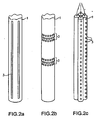
- Fig. 2 special embodiments of the tempering device 1 according to the invention are shown.
- a pipe section 1 is provided, are arranged in the gas outlet openings in the form of slots 3, through which the gas can escape.
- Fig. 2b two circular areas are provided with gas outlet openings 3, through which the preform can be supplied with gas.
- Fig. 2c are several tube pieces combined into a bundle, so as to give the tempering 1.
- gas outlet openings 3 are provided, with which the preform can be acted upon with gas.
- Each of the openings in Fig. 2 can also be used to recover the gas discharged from the preform through a gas outlet port 3 into the tempering device 1.
- certain flow profiles can be generated to temper so sharply defined zones of the preform 2.
- Fig. 3 an inventive embodiment of the method according to the invention is outlined.
- an embodiment of the device according to the invention is used, in which the temperature control device 1 is integrated into the stretch rod 11.
- a first step A the tempering device 1 is retracted with circularly arranged gas outlet openings 3 in a uniformly preheated preform 2.
- the line 4 indicates the position x as a function of the time t at which the lower end of the tempering device 1 is located.
- the tempering device 1 is not moved relative to the preform 2 for a while (step B). During this time, cooling air is blown out through the gas outlet openings 3, with which the preform 2 is selectively tempered.
- the tempering device 1 is moved out of the preform 2 again after step B (in FIG Fig. 3 not shown), whereby the process of selective tempering is completed.
- Another possible embodiment of the method according to the invention is to stretch the selectively preheated preform with the tempering device 1 in step C.
- blow molding process gas By introducing blow molding process gas into the preform 2, the preform material is extruded outwardly against an in Fig. 3 Not shown blow mold pressed, resulting in the final, outer bottle shape.
- the Formblasreagas can be introduced through the upper opening of the preform on the stretching rod 11 or by the stretch rod in the preform.
- a further possible embodiment of the method according to the invention consists of pressurizing the finished bottle from the inside with cooling gas in a step D following step C so as to achieve uniform cooling of the finished bottle.
- Fig. 4 is the initial and final state of the preform 2, as well as the finished bottle, as in the in Fig. 3 shown methods may occur.
- the preform 2 is the temperature control device 1, are provided in the gas outlet openings 3, with which the zones 10 of the preform 2 are cooled.
- the cooling results in a higher toughness of the material of the preform in the zones 10 in comparison to the parts of the preform 2 surrounding the zones 10
- Fig. 4 illustrated blow mold 5 specifies the outer shape of the finished bottle.
- step C in FIG Fig. 3 is shown from the in Fig. 4 shown Preform 2, which in Fig. 4 shown bottle, with only the inside of the bottle and that shown in dashed lines.
- the outside of the bottle is predetermined by the blow mold 5. Due to the increased toughness of the zones 10 of the preform 2, they are less extensively stretched during the blow molding process than the remaining areas.
- beads of the finished bottle which surround the bottle ring. Such beads may be capable of increasing the stability of the bottle in particular areas, such as where the bottle is to be grasped.
- Fig. 5 It is shown how advantageously a bottle with a rectangular shape is produced by the method according to the invention and the device according to the invention. In this case, a sectional view is shown as it would result in a horizontal section through the device in Figure 1.
- a preform 2 with cooled zones 10 is shown, in which a tempering device 1 with gas outlet openings 3 is located. The preform 2 surrounds the rectangular blow mold 5.
- the blow molding process expands the diameter of the preform 2, as in FIG Fig. 5 , shown on the right.
- Those regions of the preform 2 which come into contact with the blow mold 5 are stretched less strongly in the blow molding process than those regions which continue to follow the arrows in FIG Fig. 5 , right into the corners can hineinumblen.
- those zones 10 which are stretched into the corners they were only slightly stretched in the initial part of the blow molding process. This is still enough material strength present in those areas, which is then thinned in the stretching into the corners of the blow mold.
- a bottle having a desired uniform or desired uneven thickness distribution along its circumference can be produced.
- FIG. 6 A particularly advantageous embodiment of the device according to the invention is in Fig. 6 shown.
- a tempering device 1 is shown, which comprises two tubular elements 1a and 1b. Holes or arrangements of slots or similar gas outlet openings 3 are provided in both tubular elements.
- the two elements 1a and 1b are arranged so that as in Fig. 6a shown at the top, the oval gas outlet 3 right in Fig. 6a overlap. If the interior of the cane is under an increased air pressure, this may flow out through the overlapping openings of the element 1b and 1a and the preform, which in Fig. 6a which is not shown for the sake of clarity, apply gas.
- the slot-like openings do not overlap, so that no gas escapes through these openings to the outside.
- Fig. 6b is compared to Fig. 6a the inner tube 1b has been turned slightly to the right. As a result, now overlap the slot-shaped openings of the elements 1a and 1b, so that can escape through this gas to the outside, if there is a gas pressure in the interior of the elements 1a and 1b.
- the outgoing gas is applied to the preform with gas.
- the round or oval openings of the elements 1a and 1b have in Fig. 6b no overlap, so that no gas will escape through these openings to the outside.
- the element 1a is in Fig. 6a and 6b not fully shown, so that the element 1b is visible in the lower part of the figures.
- the element 1a is thus also in the lower part of the Fig. 6a and 6b to be completed accordingly.
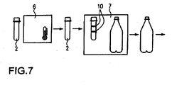
- a preheating device 6 serves to heat the preforms 2 evenly.
- the heating essentially relates to the lower peg-shaped area which is to be formed in the blow molding process.
- the collar and the area of the thread in the upper region of the preform 2 are not preheated.
- a Formblasvorraum 7 the temperature control device 1 is integrated, with which the preheated preforms are selectively tempered.
- the selectively tempered zones 10 are in Fig. 7 shown schematically. With the device 7, a bottle is then produced by means of blow molding and issued.
Landscapes
- Physics & Mathematics (AREA)
- Thermal Sciences (AREA)
- Engineering & Computer Science (AREA)
- Manufacturing & Machinery (AREA)
- Mechanical Engineering (AREA)
- Blow-Moulding Or Thermoforming Of Plastics Or The Like (AREA)
- Heat Treatment Of Articles (AREA)
Claims (10)
- Dispositif pour équilibrer en température ou tempérer des pré-ébauches ou préformes (2), comprenant une installation d'équilibrage de température (1) munie de moyens de refroidissement (3) intégrés au moins en partie à la canne d'étirage (11) d'un dispositif de moulage ou formage par soufflage (7), les pré-ébauches comportant, dans la zone supérieure, un filetage et une collerette, qui ne vont pas être déformés et ne sont pas chauffés, et comportant, sous la collerette, une zone en forme de tourillon, chauffée, qui va être déformée, caractérisé en ce que l'installation d'équilibrage en température (1) munie de moyens de refroidissement comporte au moins une installation de guidage de gaz et des orifices de sortie de gaz (3), qui sont réalisés pour refroidir sélectivement et directement les pré-ébauches (2) sur des zones (10) le long de l'axe de la pré-ébauche, en alimentant et sollicitant les pré-ébauches (2) en gaz refroidi.
- Dispositif selon la revendication 1, caractérisé en ce que l'installation de refroidissement (3) est réalisée pour permettre de refroidir les pré-ébauches (2) en plus dans des zones transversalement ou en biais par rapport à l'axe de la pré-ébauche.
- Dispositif selon la revendication 2, caractérisé en ce que l'installation de refroidissement (1) comporte au moins un orifice d'entrée de gaz pour recueillir du gaz des pré-ébauches.
- Dispositif selon l'une des revendications 1 à 3, caractérisé en ce que l'orifice d'entrée de gaz (3) et/ou l'orifice de sortie de gaz sont réalisés par une fente (3), un perçage (3), une buse (3) ou d'autres cavités ou évidements (3).
- Dispositif selon l'une des revendications 1 à 4, caractérisé en ce que plusieurs orifices d'entrée de gaz (3) et/ou plusieurs orifices de sortie de gaz sont agencés ou répartis sur des lignes.
- Dispositif selon l'une des revendications 1 à 5, caractérisé en ce que l'installation de refroidissement comporte au moins un premier élément tubulaire (1a) et un second élément tubulaire (2b) mobiles l'un par rapport à l'autre,
la disposition des orifices de sortie du premier élément tubulaire (la), dans une première position relative des éléments tubulaires mobiles l'un par rapport à l'autre, chevauche la disposition des orifices de sortie de gaz du second élément tubulaire (1b) de manière à pouvoir effectuer le refroidissement sélectif, et
la disposition des orifices de sortie du premier élément tubulaire (la), dans une seconde position relative des éléments tubulaires mobiles l'un par rapport à l'autre, chevauche la disposition des orifices de sortie de gaz du second élément tubulaire (1b) de manière à pouvoir effectuer un refroidissement uniforme régulier. - Procédé pour équilibrer en température ou tempérer des pré-ébauches ou préformes (2),
d'après lequel les pré-ébauches comportent, dans la zone supérieure, un filetage et une collerette, qui ne vont être ni déformés, ni chauffés, et comportent, sous la collerette, une zone en forme de tourillon, qui va être chauffée,
d'après lequel on refroidit les pré-ébauches directement de l'intérieur à l'aide d'une canne d'étirage (11) telle qu'utilisée dans le cadre d'un processus de moulage ou formage par soufflage,
d'après lequel on refroidit les pré-ébauches de manière sélective dans des zones (10) le long de l'axe de la pré-ébauche,
caractérisé en ce que pour leur refroidissement sélectif, les pré-ébauches (2) sont alimentées et sollicitées par un gaz refroidi, notamment de l'air, à travers des orifices de sortie de gaz (3). - Procédé selon la revendication 7, caractérisé en ce que les pré-ébauches (2) peuvent être refroidies en plus dans des zones transversalement ou en biais par rapport à l'axe de la pré-ébauche.
- Procédé selon la revendication 8 ou la revendication 9, caractérisé en ce que du gaz en provenance des pré-ébauches (2) est recueilli par l'installation de refroidissement (1).
- Procédé selon l'une des revendications 8 à 10, caractérisé en ce que l'alimentation et la sollicitation avec le gaz refroidi/chauffé consiste à faire passer le gaz à travers une première disposition d'orifices de sortie de gaz d'un premier élément tubulaire (la),
ce premier élément tubulaire (1a) entourant un second élément tubulaire (1b) muni d'une seconde disposition d'orifices de sortie de gaz,
les dispositions d'orifices de sortie de gaz du premier élément tubulaire (1a) et du second élément tubulaire (1b), dans une première position relative du premier et du second élément tubulaire, se chevauchant au moins partiellement, et le premier élément tubulaire (1a) et le second élément tubulaire (1b) étant ensuite amenés dans une seconde position relative l'un par rapport à l'autre, pour laquelle les dispositions d'orifices de sortie de gaz du premier élément tubulaire (1a) et du second élément tubulaire (1b) se chevauchent au moins en partie, de manière à pouvoir effectuer un refroidissement uniforme régulier,
ce premier élément tubulaire (1a) entourant un second élément tubulaire (1b) muni d'une seconde disposition d'orifices de sortie de gaz, les dispositions d'orifices de sortie de gaz du premier élément tubulaire (1a) et du second élément tubulaire (1b), dans une première position relative du premier et du second élément tubulaire, se chevauchant au moins partiellement, et le premier élément tubulaire (1a) et le second élément tubulaire (1b) étant ensuite amenés dans une seconde position relative l'un par rapport à l'autre, pour laquelle les dispositions d'orifices de sortie de gaz du premier élément tubulaire (1a) et du second élément tubulaire (1b) se chevauchent au moins en partie, de manière à pouvoir effectuer un refroidissement uniforme régulier.
Applications Claiming Priority (3)
| Application Number | Priority Date | Filing Date | Title |
|---|---|---|---|
| DE10144537A DE10144537B4 (de) | 2001-09-11 | 2001-09-11 | Vorrichtung und Verfahren zum Temperieren von Vorformlingen |
| DE10144537 | 2001-09-11 | ||
| PCT/EP2002/010178 WO2003022551A1 (fr) | 2001-09-11 | 2002-09-11 | Dispositif et procede pour reguler la temperature de preformes |
Publications (4)
| Publication Number | Publication Date |
|---|---|
| EP1425154A1 EP1425154A1 (fr) | 2004-06-09 |
| EP1425154B1 EP1425154B1 (fr) | 2011-11-09 |
| EP1425154B2 true EP1425154B2 (fr) | 2015-07-08 |
| EP1425154B9 EP1425154B9 (fr) | 2016-02-10 |
Family
ID=7698509
Family Applications (1)
| Application Number | Title | Priority Date | Filing Date |
|---|---|---|---|
| EP02797982.2A Expired - Lifetime EP1425154B9 (fr) | 2001-09-11 | 2002-09-11 | Dispositif et procede pour reguler la temperature de preformes |
Country Status (5)
| Country | Link |
|---|---|
| US (1) | US7687011B2 (fr) |
| EP (1) | EP1425154B9 (fr) |
| AT (1) | ATE532620T1 (fr) |
| DE (1) | DE10144537B4 (fr) |
| WO (1) | WO2003022551A1 (fr) |
Families Citing this family (12)
| Publication number | Priority date | Publication date | Assignee | Title |
|---|---|---|---|---|
| DE10144537B4 (de) † | 2001-09-11 | 2010-07-22 | Krones Ag | Vorrichtung und Verfahren zum Temperieren von Vorformlingen |
| US7264464B2 (en) * | 2003-06-09 | 2007-09-04 | Husky Injection Molding Systems Ltd. | Cooling tube with a low friction coating |
| DE10355511A1 (de) | 2003-11-24 | 2005-06-09 | Biotronik Gmbh & Co. Kg | Endovasculäres Implantat mit einer aktiven Beschichtung |
| DE102008047891A1 (de) | 2008-09-18 | 2010-03-25 | Krones Ag | Temperierte Reckstange |
| DE102009035868A1 (de) | 2009-07-31 | 2011-02-03 | Krones Ag | Vorrichtung zum Umformen von Kunststoffvorformlingen mit synchroner Erwärmung und Reckung |
| DE102010007542A1 (de) * | 2010-02-08 | 2011-08-11 | KHS Corpoplast GmbH, 22145 | Verfahren und Vorrichtung zur Blasformung von Behältern |
| EP2447172A1 (fr) * | 2010-11-02 | 2012-05-02 | Stefano Boido | Dispositif pour chauffer des récipients |
| WO2015116549A1 (fr) * | 2014-01-28 | 2015-08-06 | Gojo Industries, Inc. | Appareil et procédé pour préchauffer des préformes à deux étages |
| CA3088197C (fr) | 2018-01-11 | 2023-06-20 | Husky Injection Molding Systems Ltd. | Procede et appareil pour donner une forme finale a des contenants en utilisant un liquide devant etre contenu dans lesdits contenants |
| CN109648824B (zh) * | 2019-01-29 | 2021-03-02 | 广州纯元科技有限公司 | 一种用于塑料桶生产的吹塑装置 |
| US12064916B2 (en) * | 2019-07-05 | 2024-08-20 | Fresenius Kabi Deutschland Gmbh | Ampoule filled with a medical liquid and method for producing same and system used therefor |
| DE102021131986A1 (de) | 2021-12-03 | 2023-06-07 | Wafios Aktiengesellschaft | Vorrichtung zum Erwärmen von stangenförmigem Material und Biegemaschine damit |
Citations (3)
| Publication number | Priority date | Publication date | Assignee | Title |
|---|---|---|---|---|
| US3439380A (en) † | 1966-11-07 | 1969-04-22 | Phillips Petroleum Co | Apparatus for blow molding biaxially oriented articles |
| US4285657A (en) † | 1979-12-03 | 1981-08-25 | Ryder Leonard B | Injection blow molding apparatus |
| US7687011B2 (en) † | 2001-09-11 | 2010-03-30 | Krones Ag | Device and method for controlling the temperature of preforms |
Family Cites Families (21)
| Publication number | Priority date | Publication date | Assignee | Title |
|---|---|---|---|---|
| DE1816489B2 (de) | 1968-12-23 | 1972-03-30 | Heidenreich & Harbeck Gmbh, 2000 Hamburg | Verfahren und vorrichtung zur wanddickenregulierung beim blasen von hohlkoerpern |
| US3787170A (en) * | 1971-05-13 | 1974-01-22 | Phillips Petroleum Co | Rapid heating of parison preforms |
| US3934743A (en) | 1972-12-29 | 1976-01-27 | American Can Company | Blow molded, oriented plastic bottle and method for making same |
| AU508942B2 (en) * | 1977-12-02 | 1980-04-17 | Yoshino Kogyosho Co., Ltd. | Preparing saturated polyester resin bottles |
| US4151249A (en) * | 1978-01-05 | 1979-04-24 | Owens-Illinois, Inc. | Method of making a blown bottle with internal ribs |
| JPS57117929A (en) * | 1981-01-16 | 1982-07-22 | Dainippon Printing Co Ltd | Manufacture of biaxially stretched saturated polyester resin container by blow molding |
| US4564497A (en) | 1982-07-28 | 1986-01-14 | Yoshino Kogyosho Co., Ltd. | Method of producing bottles of saturated polyester |
| JPS6061228A (ja) * | 1983-09-14 | 1985-04-09 | Mitsubishi Plastics Ind Ltd | プラスチックボトルの成形方法 |
| JPS6073830A (ja) | 1983-09-30 | 1985-04-26 | Katashi Aoki | 偏平または角形びんなどの容器のブロ−成形方法 |
| US4605839A (en) * | 1984-12-21 | 1986-08-12 | Adolph Coors Company | Dual parison heating reflector and method |
| JPS6277919A (ja) * | 1985-10-01 | 1987-04-10 | Mitsubishi Plastics Ind Ltd | ボトルのブロ−成形方法 |
| JPH0761675B2 (ja) | 1990-06-18 | 1995-07-05 | 凸版印刷株式会社 | プラスチックボトルの製造方法 |
| US5232641A (en) | 1991-01-25 | 1993-08-03 | Williamson James T | Rapid cool process |
| US5290506A (en) * | 1991-04-30 | 1994-03-01 | Nissei Asb Machine Co., Ltd. | Process of injection stretch blow molding hollow article having thick-walled bottom |
| FR2678542B1 (fr) * | 1991-07-01 | 1993-10-29 | Sidel | Procede et installation pour le chauffage, par rayonnement infrarouge, de preformes en matiere plastique, notamment en pet, destinees a la fabrication de recipients. |
| JP3200259B2 (ja) | 1992-09-25 | 2001-08-20 | 日精エー・エス・ビー機械株式会社 | 自立瓶の二軸延伸吹込成形方法及びそれに用いるプリフォーム |
| JP3255485B2 (ja) | 1993-03-25 | 2002-02-12 | 日精エー・エス・ビー機械株式会社 | ブロー成形機 |
| JP2963644B2 (ja) | 1995-07-06 | 1999-10-18 | 花王株式会社 | くびれ形状を有するプラスチックボトルの成形方法 |
| DE19608570A1 (de) * | 1996-03-06 | 1997-09-11 | Krupp Corpoplast Masch | Verfahren zur Temperierung von Vorformlingen sowie Vorrichtung zur Temperierung |
| US6171541B1 (en) | 1998-03-31 | 2001-01-09 | Husky Injection Molding Systems Ltd. | Preform post-mold cooling method and apparatus |
| JP3577996B2 (ja) * | 1999-06-02 | 2004-10-20 | 東洋製罐株式会社 | 二軸延伸ブロー成形容器の製造方法及びその装置 |
-
2001
- 2001-09-11 DE DE10144537A patent/DE10144537B4/de not_active Expired - Fee Related
-
2002
- 2002-09-11 EP EP02797982.2A patent/EP1425154B9/fr not_active Expired - Lifetime
- 2002-09-11 US US10/487,007 patent/US7687011B2/en not_active Expired - Fee Related
- 2002-09-11 WO PCT/EP2002/010178 patent/WO2003022551A1/fr not_active Ceased
- 2002-09-11 AT AT02797982T patent/ATE532620T1/de active
Patent Citations (3)
| Publication number | Priority date | Publication date | Assignee | Title |
|---|---|---|---|---|
| US3439380A (en) † | 1966-11-07 | 1969-04-22 | Phillips Petroleum Co | Apparatus for blow molding biaxially oriented articles |
| US4285657A (en) † | 1979-12-03 | 1981-08-25 | Ryder Leonard B | Injection blow molding apparatus |
| US7687011B2 (en) † | 2001-09-11 | 2010-03-30 | Krones Ag | Device and method for controlling the temperature of preforms |
Also Published As
| Publication number | Publication date |
|---|---|
| US20050046085A1 (en) | 2005-03-03 |
| EP1425154B1 (fr) | 2011-11-09 |
| ATE532620T1 (de) | 2011-11-15 |
| US7687011B2 (en) | 2010-03-30 |
| DE10144537A1 (de) | 2003-03-27 |
| EP1425154B9 (fr) | 2016-02-10 |
| WO2003022551A1 (fr) | 2003-03-20 |
| EP1425154A1 (fr) | 2004-06-09 |
| DE10144537B4 (de) | 2010-07-22 |
Similar Documents
| Publication | Publication Date | Title |
|---|---|---|
| DE60015577T2 (de) | Blasformverfahren und blasformvorrichtung zum herstellen von pasteurisierbaren behältern | |
| DE69805347T2 (de) | Blasformverfahren zur Herstellung von wärmebeständigen Behältern | |
| DE10038158B4 (de) | Verfahren und Vorrichtung zum Verbinden von Gegenständen mittels plastisch verformbarer Verbindungskörper | |
| EP1425154B2 (fr) | Dispositif et procede pour reguler la temperature de preformes | |
| EP2753465B1 (fr) | Dispositif de transport de preformes pour le moulage par soufflage de recipients | |
| DE68927578T2 (de) | Verfahren und Vorrichtung zum Blasformen | |
| CH679470A5 (fr) | ||
| DE1097662B (de) | Vorrichtung zum Herstellen von Hohlkoerpern aus thermoplastischem Kunststoff nach der Methode des Aufblasens eines Vorformlings | |
| EP1226015B1 (fr) | Procede de production de contenants tubulaires | |
| DE3243909C2 (fr) | ||
| EP3294526A1 (fr) | Procédé de thermorégulation non homogène de préformes | |
| EP3571035B1 (fr) | Mandrin à changement rapide intégrant un serrage actif de préforme | |
| DE19833006B4 (de) | Verfahren und Vorrichtung zur Herstellung rohrförmiger gebogener Hohlkörper durch Innenhochdruckumformen | |
| CH668577A5 (de) | Verfahren zur herstellung eines kunststoffbehaelters. | |
| DE4306045C2 (de) | Blasformungsverfahren für harzartige Formprodukte und Vorrichtung dafür | |
| DE3101284C2 (de) | Verfahren zum Formen des offenen Endabschnittes eines einen geschlossenen Boden aufweisenden Vorformlings für das Blasformen eines Hohlkörpers aus thermoplastischem Kunststoff, insbesondere einer Flasche, und Vorrichtung zum Durchführen des Verfahrens | |
| DE2543640B2 (de) | Verfahren und Vorrichtung zum Herstellen eines Vorformlings für das Blasformen eines Hohlkörpers | |
| EP1660301B1 (fr) | Procede et dispositif de moulage par soufflage de recipients | |
| DE2500185C2 (de) | Blasformmaschine | |
| DE2504740A1 (de) | Vorrichtung und verfahren zur herstellung von zweiachsig ausgerichteten gegenstaenden durch blasformen | |
| DE102009022374A1 (de) | Blasform zur Herstellung ovaler Kunststoffbehältnisse | |
| DE69229058T2 (de) | Verfahren zum blasformen von rohrfoermigen behaeltern | |
| DE102021128341B4 (de) | Verfahren zum Formen eines in eine Form einer Form- und Füllstation eingesetzten Vorformlings zu einem Behälter und Befüllen des sich formenden Behälters mit flüssigem Füllgut | |
| EP3939771B1 (fr) | Dispositif de transformation de préformes en matière plastique en récipients en matière plastique par refroidissement des préformes | |
| DE102022125665B4 (de) | Verfahren, Vorrichtung und Anlage zum Herstellen eines mit flüssigem Füllgut befüllten Behälters aus einem thermisch konditionierten Vorformling sowie die Verwendung der Vorrichtung und/oder der Anlage |
Legal Events
| Date | Code | Title | Description |
|---|---|---|---|
| PUAI | Public reference made under article 153(3) epc to a published international application that has entered the european phase |
Free format text: ORIGINAL CODE: 0009012 |
|
| 17P | Request for examination filed |
Effective date: 20040130 |
|
| AK | Designated contracting states |
Kind code of ref document: A1 Designated state(s): AT BE BG CH CY CZ DE DK EE ES FI FR GB GR IE IT LI LU MC NL PT SE SK TR |
|
| AX | Request for extension of the european patent |
Extension state: AL LT LV MK RO SI |
|
| RIN1 | Information on inventor provided before grant (corrected) |
Inventor name: DEYERL, HEINRICH Inventor name: ASBRAND, HELMUT Inventor name: VOTH, KLAUS |
|
| 17Q | First examination report despatched |
Effective date: 20050107 |
|
| 17Q | First examination report despatched |
Effective date: 20050107 |
|
| GRAP | Despatch of communication of intention to grant a patent |
Free format text: ORIGINAL CODE: EPIDOSNIGR1 |
|
| GRAS | Grant fee paid |
Free format text: ORIGINAL CODE: EPIDOSNIGR3 |
|
| GRAA | (expected) grant |
Free format text: ORIGINAL CODE: 0009210 |
|
| AK | Designated contracting states |
Kind code of ref document: B1 Designated state(s): AT BE BG CH CY CZ DE DK EE ES FI FR GB GR IE IT LI LU MC NL PT SE SK TR |
|
| REG | Reference to a national code |
Ref country code: GB Ref legal event code: FG4D Free format text: NOT ENGLISH |
|
| REG | Reference to a national code |
Ref country code: CH Ref legal event code: EP |
|
| REG | Reference to a national code |
Ref country code: IE Ref legal event code: FG4D Free format text: LANGUAGE OF EP DOCUMENT: GERMAN |
|
| REG | Reference to a national code |
Ref country code: DE Ref legal event code: R096 Ref document number: 50215283 Country of ref document: DE Effective date: 20120112 |
|
| REG | Reference to a national code |
Ref country code: NL Ref legal event code: VDEP Effective date: 20111109 |
|
| PG25 | Lapsed in a contracting state [announced via postgrant information from national office to epo] |
Ref country code: NL Free format text: LAPSE BECAUSE OF FAILURE TO SUBMIT A TRANSLATION OF THE DESCRIPTION OR TO PAY THE FEE WITHIN THE PRESCRIBED TIME-LIMIT Effective date: 20111109 Ref country code: PT Free format text: LAPSE BECAUSE OF FAILURE TO SUBMIT A TRANSLATION OF THE DESCRIPTION OR TO PAY THE FEE WITHIN THE PRESCRIBED TIME-LIMIT Effective date: 20120309 Ref country code: GR Free format text: LAPSE BECAUSE OF FAILURE TO SUBMIT A TRANSLATION OF THE DESCRIPTION OR TO PAY THE FEE WITHIN THE PRESCRIBED TIME-LIMIT Effective date: 20120210 Ref country code: SE Free format text: LAPSE BECAUSE OF FAILURE TO SUBMIT A TRANSLATION OF THE DESCRIPTION OR TO PAY THE FEE WITHIN THE PRESCRIBED TIME-LIMIT Effective date: 20111109 |
|
| REG | Reference to a national code |
Ref country code: IE Ref legal event code: FD4D |
|
| PG25 | Lapsed in a contracting state [announced via postgrant information from national office to epo] |
Ref country code: CY Free format text: LAPSE BECAUSE OF FAILURE TO SUBMIT A TRANSLATION OF THE DESCRIPTION OR TO PAY THE FEE WITHIN THE PRESCRIBED TIME-LIMIT Effective date: 20111109 |
|
| PG25 | Lapsed in a contracting state [announced via postgrant information from national office to epo] |
Ref country code: CZ Free format text: LAPSE BECAUSE OF FAILURE TO SUBMIT A TRANSLATION OF THE DESCRIPTION OR TO PAY THE FEE WITHIN THE PRESCRIBED TIME-LIMIT Effective date: 20111109 Ref country code: SK Free format text: LAPSE BECAUSE OF FAILURE TO SUBMIT A TRANSLATION OF THE DESCRIPTION OR TO PAY THE FEE WITHIN THE PRESCRIBED TIME-LIMIT Effective date: 20111109 Ref country code: DK Free format text: LAPSE BECAUSE OF FAILURE TO SUBMIT A TRANSLATION OF THE DESCRIPTION OR TO PAY THE FEE WITHIN THE PRESCRIBED TIME-LIMIT Effective date: 20111109 Ref country code: IE Free format text: LAPSE BECAUSE OF FAILURE TO SUBMIT A TRANSLATION OF THE DESCRIPTION OR TO PAY THE FEE WITHIN THE PRESCRIBED TIME-LIMIT Effective date: 20111109 Ref country code: BG Free format text: LAPSE BECAUSE OF FAILURE TO SUBMIT A TRANSLATION OF THE DESCRIPTION OR TO PAY THE FEE WITHIN THE PRESCRIBED TIME-LIMIT Effective date: 20120209 Ref country code: EE Free format text: LAPSE BECAUSE OF FAILURE TO SUBMIT A TRANSLATION OF THE DESCRIPTION OR TO PAY THE FEE WITHIN THE PRESCRIBED TIME-LIMIT Effective date: 20111109 |
|
| PLAZ | Examination of admissibility of opposition: despatch of communication + time limit |
Free format text: ORIGINAL CODE: EPIDOSNOPE2 |
|
| PLBI | Opposition filed |
Free format text: ORIGINAL CODE: 0009260 |
|
| 26 | Opposition filed |
Opponent name: SIDEL PARTICIPATIONS Effective date: 20120726 |
|
| PLBA | Examination of admissibility of opposition: reply received |
Free format text: ORIGINAL CODE: EPIDOSNOPE4 |
|
| PLAB | Opposition data, opponent's data or that of the opponent's representative modified |
Free format text: ORIGINAL CODE: 0009299OPPO |
|
| PLAX | Notice of opposition and request to file observation + time limit sent |
Free format text: ORIGINAL CODE: EPIDOSNOBS2 |
|
| R26 | Opposition filed (corrected) |
Opponent name: SIDEL PARTICIPATIONS Effective date: 20120726 |
|
| REG | Reference to a national code |
Ref country code: DE Ref legal event code: R026 Ref document number: 50215283 Country of ref document: DE Effective date: 20120726 |
|
| PLBB | Reply of patent proprietor to notice(s) of opposition received |
Free format text: ORIGINAL CODE: EPIDOSNOBS3 |
|
| BERE | Be: lapsed |
Owner name: KRONES A.G. Effective date: 20120930 |
|
| PG25 | Lapsed in a contracting state [announced via postgrant information from national office to epo] |
Ref country code: MC Free format text: LAPSE BECAUSE OF NON-PAYMENT OF DUE FEES Effective date: 20120930 Ref country code: ES Free format text: LAPSE BECAUSE OF FAILURE TO SUBMIT A TRANSLATION OF THE DESCRIPTION OR TO PAY THE FEE WITHIN THE PRESCRIBED TIME-LIMIT Effective date: 20120220 |
|
| REG | Reference to a national code |
Ref country code: CH Ref legal event code: PL |
|
| GBPC | Gb: european patent ceased through non-payment of renewal fee |
Effective date: 20120911 |
|
| PG25 | Lapsed in a contracting state [announced via postgrant information from national office to epo] |
Ref country code: FI Free format text: LAPSE BECAUSE OF FAILURE TO SUBMIT A TRANSLATION OF THE DESCRIPTION OR TO PAY THE FEE WITHIN THE PRESCRIBED TIME-LIMIT Effective date: 20111109 |
|
| PG25 | Lapsed in a contracting state [announced via postgrant information from national office to epo] |
Ref country code: CH Free format text: LAPSE BECAUSE OF NON-PAYMENT OF DUE FEES Effective date: 20120930 Ref country code: GB Free format text: LAPSE BECAUSE OF NON-PAYMENT OF DUE FEES Effective date: 20120911 Ref country code: LI Free format text: LAPSE BECAUSE OF NON-PAYMENT OF DUE FEES Effective date: 20120930 Ref country code: BE Free format text: LAPSE BECAUSE OF NON-PAYMENT OF DUE FEES Effective date: 20120930 |
|
| REG | Reference to a national code |
Ref country code: AT Ref legal event code: MM01 Ref document number: 532620 Country of ref document: AT Kind code of ref document: T Effective date: 20120911 |
|
| PG25 | Lapsed in a contracting state [announced via postgrant information from national office to epo] |
Ref country code: AT Free format text: LAPSE BECAUSE OF NON-PAYMENT OF DUE FEES Effective date: 20120911 |
|
| PG25 | Lapsed in a contracting state [announced via postgrant information from national office to epo] |
Ref country code: TR Free format text: LAPSE BECAUSE OF FAILURE TO SUBMIT A TRANSLATION OF THE DESCRIPTION OR TO PAY THE FEE WITHIN THE PRESCRIBED TIME-LIMIT Effective date: 20111109 |
|
| PG25 | Lapsed in a contracting state [announced via postgrant information from national office to epo] |
Ref country code: LU Free format text: LAPSE BECAUSE OF NON-PAYMENT OF DUE FEES Effective date: 20120911 |
|
| PUAH | Patent maintained in amended form |
Free format text: ORIGINAL CODE: 0009272 |
|
| STAA | Information on the status of an ep patent application or granted ep patent |
Free format text: STATUS: PATENT MAINTAINED AS AMENDED |
|
| 27A | Patent maintained in amended form |
Effective date: 20150708 |
|
| AK | Designated contracting states |
Kind code of ref document: B2 Designated state(s): AT BE BG CH CY CZ DE DK EE ES FI FR GB GR IE IT LI LU MC NL PT SE SK TR |
|
| REG | Reference to a national code |
Ref country code: DE Ref legal event code: R102 Ref document number: 50215283 Country of ref document: DE |
|
| REG | Reference to a national code |
Ref country code: FR Ref legal event code: PLFP Year of fee payment: 14 |
|
| REG | Reference to a national code |
Ref country code: FR Ref legal event code: PLFP Year of fee payment: 15 |
|
| REG | Reference to a national code |
Ref country code: FR Ref legal event code: PLFP Year of fee payment: 16 |
|
| REG | Reference to a national code |
Ref country code: FR Ref legal event code: PLFP Year of fee payment: 17 |
|
| PGFP | Annual fee paid to national office [announced via postgrant information from national office to epo] |
Ref country code: FR Payment date: 20180813 Year of fee payment: 17 Ref country code: DE Payment date: 20180828 Year of fee payment: 17 Ref country code: IT Payment date: 20180919 Year of fee payment: 17 |
|
| REG | Reference to a national code |
Ref country code: DE Ref legal event code: R119 Ref document number: 50215283 Country of ref document: DE |
|
| PG25 | Lapsed in a contracting state [announced via postgrant information from national office to epo] |
Ref country code: DE Free format text: LAPSE BECAUSE OF NON-PAYMENT OF DUE FEES Effective date: 20200401 |
|
| PG25 | Lapsed in a contracting state [announced via postgrant information from national office to epo] |
Ref country code: IT Free format text: LAPSE BECAUSE OF NON-PAYMENT OF DUE FEES Effective date: 20190911 |
|
| PG25 | Lapsed in a contracting state [announced via postgrant information from national office to epo] |
Ref country code: FR Free format text: LAPSE BECAUSE OF NON-PAYMENT OF DUE FEES Effective date: 20190930 |