EP1425954A1 - Dispositif de nettoyage pour un tube de décharge d'une machine de récolte - Google Patents
Dispositif de nettoyage pour un tube de décharge d'une machine de récolte Download PDFInfo
- Publication number
- EP1425954A1 EP1425954A1 EP03027714A EP03027714A EP1425954A1 EP 1425954 A1 EP1425954 A1 EP 1425954A1 EP 03027714 A EP03027714 A EP 03027714A EP 03027714 A EP03027714 A EP 03027714A EP 1425954 A1 EP1425954 A1 EP 1425954A1
- Authority
- EP
- European Patent Office
- Prior art keywords
- nozzles
- tube
- cleaning device
- unloading
- unloading tube
- Prior art date
- Legal status (The legal status is an assumption and is not a legal conclusion. Google has not performed a legal analysis and makes no representation as to the accuracy of the status listed.)
- Granted
Links
- 238000004140 cleaning Methods 0.000 title claims description 29
- 238000003306 harvesting Methods 0.000 claims description 11
- 239000007788 liquid Substances 0.000 claims description 2
- 230000009969 flowable effect Effects 0.000 claims 2
- 238000000034 method Methods 0.000 abstract description 4
- 238000011144 upstream manufacturing Methods 0.000 abstract description 3
- 230000000149 penetrating effect Effects 0.000 abstract 1
- 230000008878 coupling Effects 0.000 description 3
- 238000010168 coupling process Methods 0.000 description 3
- 238000005859 coupling reaction Methods 0.000 description 3
- 235000003869 genetically modified organism Nutrition 0.000 description 3
- JEIPFZHSYJVQDO-UHFFFAOYSA-N iron(III) oxide Inorganic materials O=[Fe]O[Fe]=O JEIPFZHSYJVQDO-UHFFFAOYSA-N 0.000 description 3
- 239000010908 plant waste Substances 0.000 description 3
- 239000010902 straw Substances 0.000 description 3
- 241000196324 Embryophyta Species 0.000 description 2
- 241001124569 Lycaenidae Species 0.000 description 2
- 240000008042 Zea mays Species 0.000 description 2
- 235000005824 Zea mays ssp. parviglumis Nutrition 0.000 description 2
- 235000002017 Zea mays subsp mays Nutrition 0.000 description 2
- 235000005822 corn Nutrition 0.000 description 2
- 230000002068 genetic effect Effects 0.000 description 2
- 238000002955 isolation Methods 0.000 description 2
- 239000000203 mixture Substances 0.000 description 2
- 230000007704 transition Effects 0.000 description 2
- 235000013311 vegetables Nutrition 0.000 description 2
- 229920000742 Cotton Polymers 0.000 description 1
- LFQSCWFLJHTTHZ-UHFFFAOYSA-N Ethanol Chemical compound CCO LFQSCWFLJHTTHZ-UHFFFAOYSA-N 0.000 description 1
- 244000068988 Glycine max Species 0.000 description 1
- 235000010469 Glycine max Nutrition 0.000 description 1
- 230000000712 assembly Effects 0.000 description 1
- 238000000429 assembly Methods 0.000 description 1
- 108010081181 calcium-binding protein (brain) Proteins 0.000 description 1
- 238000012790 confirmation Methods 0.000 description 1
- 239000000356 contaminant Substances 0.000 description 1
- 238000010586 diagram Methods 0.000 description 1
- 238000009826 distribution Methods 0.000 description 1
- 230000007613 environmental effect Effects 0.000 description 1
- 239000000835 fiber Substances 0.000 description 1
- 244000037671 genetically modified crops Species 0.000 description 1
- 239000004009 herbicide Substances 0.000 description 1
- 230000003116 impacting effect Effects 0.000 description 1
- 239000012535 impurity Substances 0.000 description 1
- 238000004519 manufacturing process Methods 0.000 description 1
- 238000002156 mixing Methods 0.000 description 1
- 239000000575 pesticide Substances 0.000 description 1
- 239000008149 soap solution Substances 0.000 description 1
- 239000000243 solution Substances 0.000 description 1
- 241000894007 species Species 0.000 description 1
- 238000003860 storage Methods 0.000 description 1
- 239000000126 substance Substances 0.000 description 1
- XLYOFNOQVPJJNP-UHFFFAOYSA-N water Substances O XLYOFNOQVPJJNP-UHFFFAOYSA-N 0.000 description 1
- 238000003466 welding Methods 0.000 description 1
Images


Classifications
-
- B—PERFORMING OPERATIONS; TRANSPORTING
- B65—CONVEYING; PACKING; STORING; HANDLING THIN OR FILAMENTARY MATERIAL
- B65G—TRANSPORT OR STORAGE DEVICES, e.g. CONVEYORS FOR LOADING OR TIPPING, SHOP CONVEYOR SYSTEMS OR PNEUMATIC TUBE CONVEYORS
- B65G45/00—Lubricating, cleaning, or clearing devices
- B65G45/005—Cleaning conveyor screws
-
- A—HUMAN NECESSITIES
- A01—AGRICULTURE; FORESTRY; ANIMAL HUSBANDRY; HUNTING; TRAPPING; FISHING
- A01D—HARVESTING; MOWING
- A01D41/00—Combines, i.e. harvesters or mowers combined with threshing devices
- A01D41/12—Details of combines
- A01D41/1208—Tanks for grain or chaff
-
- B—PERFORMING OPERATIONS; TRANSPORTING
- B65—CONVEYING; PACKING; STORING; HANDLING THIN OR FILAMENTARY MATERIAL
- B65G—TRANSPORT OR STORAGE DEVICES, e.g. CONVEYORS FOR LOADING OR TIPPING, SHOP CONVEYOR SYSTEMS OR PNEUMATIC TUBE CONVEYORS
- B65G2201/00—Indexing codes relating to handling devices, e.g. conveyors, characterised by the type of product or load being conveyed or handled
- B65G2201/02—Articles
- B65G2201/0202—Agricultural and processed food products
Definitions
- the invention relates to a cleaning device for a Unloading tube of a harvesting machine, especially one Combine.
- Agricultural crops can be considered edible Crop, non-edible crop, genetically modified Organisms (GMO), non-genetically modified organisms, organically grown, pesticide-free or equivalent Properties are classified.
- Inedible crop can, for example, plants that supply fibers, cotton or Be rubber.
- Genetically modified crops can be vegetables, that has been genetically manipulated to determine the shelf life to extend compared to traditionally grown vegetables.
- Organically grown crop is harvested from plants that without exposure to certain pesticides, herbicides or other chemicals have been grown.
- the crop can be according to specific properties or Specifications are grown.
- the properties of the crop can on the genetic composition of the crop or based on crop cultivation practices, or both. It for example, a certain type of corn can be grown, one due to genetic or environmental factors has greater oil content than other species. Similarly, can a certain type of soybeans are grown that one other protein content or another desirable Property.
- One processor, one pharmaceutical Society, a manufacturer or another affected person have a desire to produce agricultural products with specific Properties from a grower or other supplier too purchase. The grower or supplier may wish for Harvest crops with specific properties at a higher price demand than for a commercially available crop. The buyer of the agricultural product can provide sufficient confirmation wish the purchased agricultural product actually has the properties sought.
- the invention provides a nozzle system and design Use in areas of harvesters to be cleaned ready.
- a current-based cleaning system for a discharge tube Harvester such as a combine harvester.
- the unloading tube contains a discharge screw conveyor and a variety of nozzles, which are usually partially inside the discharge tube are attached.
- the nozzles have outlet openings, which are oriented essentially in the longitudinal direction of the unloading tube are high to the inside of the discharge tube with currents Suspend speed and thereby cleaning the To cause discharge of grain and other residues.
- the nozzles are connected to lines that are pressurized medium provide. That for cleaning the discharge tube from the nozzles flowing medium can be air, another gas or gas mixture or be a liquid, such as water, alcohol, or Soap solution.
- the lines can be fitted with suitable valves be connected.
- the nozzles can have housings or bodies that have a wall penetrate the discharge tube.
- the bodies have within the Unloading tube a profile tapered in the direction of flow to the Resistance to the grain flow in the unloading tube during normal To minimize unloading.
- the nozzles are in the longitudinal direction of the unloading tube spaced apart. They are preferably 45 degrees above a bottom of the unloading tube, their Exit openings preferably about 10 degrees from the Horizontal are inclined downwards.
- the discharge screw conveyor can rotate while air is in the discharge tube is directed.
- the nozzles can be operated in succession and in groups of nozzles are, first the nozzles at the inlet end and then the Nozzles near the outlet end of the discharge tube are operated.
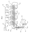
- Figures 1 and 2 show an agricultural Combine harvester 10 having a supporting structure 12 engaged has means 14 located on the ground, which are from of the supporting structure 12 extend downwards.
- Such one Combine harvester is described in detail in US 6,285,198 the disclosure of which is incorporated by reference into the present Documents is included.
- the invention can be used on any other Types of combine harvesters are used, such as conventional ones Straw walker machines.
- a cutter 16 is used to Harvest crop and feed it to an inclined conveyor 18.
- the crop is one by the feeder 18 Guide drum 20 supplied.
- the guide drum 20 guides the crop up through an inlet transition section 22 to one axial crop processing unit 24.
- the axial crop processing unit 24 is between the side walls of the combine 10 arranged and supported by them.
- the axial crop processing unit 24 comprises an axial one Rotor housing 26 and one arranged in the rotor housing 26 axial rotor 28.
- the harvested crop passes through the inlet transition section 22 into the rotor housing 26.
- the rotor 28 is with a loading section, a threshing section and equipped with a separating section.
- the rotor housing 26 has each a corresponding loading section, threshing section and Separating portion.
- Both crop processing sections of the rotor 28, the threshing section and the separating section are with good engagement assemblies fitted.
- the threshing section of the rotor housing 26 is equipped with a concave and the separating section with a rust. Grains and chaff released from the mat fall through the concave and the grate.
- the concave and the Rust prevents the passage of crop that is larger than grain or Kaff, in the cleaning system 34th
- the clean grain will then through an elevator 36 for clean grain one Filling screw conveyor 38 supplied.
- the filling screw conveyor 38 promotes the grain in a grain tank 40 or Grain bin.
- the elevator 36 for clean grain and the Filling screw conveyor 38 comprise means for moving the clean grain from the grain bottom of the combine into one Storage container, which is formed by the grain tank 40.
- the corn is discharged from the grain tank 40 by an unloading screw conveyor 57 away.
- the discharge drum 46 conveys the straw to Combine 10 back.
- the operation of the Combine harvester 10 is operated from an operator's cab 48.
- Unloading screw conveyor 56 and 58 the grain to the side of the Grain tanks 40, where it with the discharge screw conveyor 57 in Comes in contact with the clean grain by a vertical Discharge tube 61 and a horizontal discharge tube 59 conducts.
- the Unloading screw conveyor 57 comprises a vertical section 57a, which is at least partially within the unloading tube 61 is a right-angle gear 57b, and one horizontal portion 57c within the discharge tube 59.
- the discharge tube 59 normally from the side of the combine 10 to the outside extend so that clean grain easier in a cart or Trailer can be directed.
- the grain tank 40 comprises a trough 60, which is a larger one Includes trough area 70 and a smaller trough area 72, which the horizontal unloading screw conveyors 56 and 58 take up.
- the trough 60 is a loading case or sump 64 open towards.
- the vertical section 57a of the Unloading screw conveyor 57 extends through the vertical Pipe 61 and in the swamp 64. That through the horizontal Unloading screw conveyors 56 and 58 are conveyed to the grain Sump 64 dispensed and by means of the vertical section 57a through the tube 61 and by means of the horizontal section 57 c removed through the discharge tube 59.
- FIG. 3 schematically shows an inventive one Cleaning system that works with air.
- An air supply 100 indicates air under pressure via a quick coupling 103 a valve device 102.
- the quick coupling 103 can be a threaded or other type of Coupling used or be waived.
- the Air supply 100 may be outside of combine 10 are located.
- the valve device 102 comprises branch lines 104 that Air to stationary nozzles 106 or alternative nozzles 306 (such as described below).
- a isolation valve 105 is in each Branch line 104 is provided. As described below pressurized air is applied to the nozzles 106, 306, to remove grain and contaminants from the discharge tube 59 remove.
- the driven rotating system 112 includes one with 12V operated DC motor 138 which has a pulley 140 drives a belt 142 when the motor 138 is activated during cleaning operation.
- the strap 142 drives a pulley 144 which drives a gear 146 that in normal grain unloading operation from the drive train of the Combine 10 is driven at high speed.
- the Gear 146 drives a chain 148, which is a gear 150 drives a right angle gear 152 that drives the unloading screw conveyor 57.
- the relatively small motor 138 drives the cleaning operation Unloading screw conveyor 57 at a slow speed on.
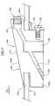
- FIG. 4 shows the horizontal unloading tube 59 in one perspective cross section.
- a nozzle 106 is shown.
- the Nozzle 106 includes a nozzle body 207 that is under pressure Air to a nozzle element 208 with an outlet opening 209 emits.
- the nozzle body 207 extends into the discharge tube 59 and nozzle member 208 is downstream lying end of the discharge tube 59 opened.
- the nozzle 106 is at an angle G above the 0 degree bottom of the Unloading tube 59 arranged.
- the angle G is preferably approximately 45 degrees.
- the outlet opening 209 of the nozzle element 208 is included directed downwards at an angle H.
- the angle H is preferably about 10 degrees.
- the nozzle body 207 includes a base block portion 207a and an inner one Block section 207b.
- a slot 207c is in the base block section 207a adjacent to the inner block portion 207b at one arranged upstream end of the nozzle body 207.
- a clamp bracket 220 is on with a screw 222 a downstream surface 207d of the base block portion 207a attached.
- a gap 207e is between a lower one Surface of the inner block portion 207b and an upper surface the clamp bracket 220 is formed.
- the clamp bracket 220 includes a slot 220a to tightly clamp the bracket 220 against one To push wall 223 of the combine 10, such as. B. the Wall of the discharge tube 59 before the screw 222 is tightened.
- An alternative design for nozzle 106 includes one snap-in plastic nozzle body, similar to that nozzle body described above, including the Base block section and the inner block section, which as are formed in one piece structure and no other means for Require connection.
- nozzle 106 includes this Nozzle element 208 that fits into an opening 228 in the interior Block section 207b is screwed.
- a through hole 232 through the base block portion 207a and the inner Block section 207b is after its manufacture by a Welding plug 234 blocked.
- the through hole 232 is communicating with opening 228.
- the nozzle element 208 can installed using a hexagon socket wrench with the nozzle element 208 in the opening 228 in the Nozzle body 207 is screwed in.
- An inlet bore 238 extends substantially perpendicular to a lower one Surface of the base block portion 207a and cuts the through hole 232.
- the inlet hole 238 is with a Thread to accommodate an air supply fitting.
- the inner block portion 207b is chamfered to an incline to form upper surface 244, the distance of which from the inner Surface of the discharge tube 59 in the direction of the grain flow 248 increases. Because of this bevel, the nozzle body 207 is in front unwanted wear protected by impacting grain, and also clogging of the unloading screw conveyor 57 with grain due to dragging the grain flow or disturbances is prevented within the unloading tube 59.
- the nozzle 106 is on and in a rectangular opening 250 in the wall 223 attached.
- the slot 207c takes a section the wall 223 and the clamp bracket 220 is against the wall 223 is pushed and the screw 222 is tightened to the wall 223 to be recorded.
- the inner block section 207b is located thus on the inside of the wall 223 and the Base block section 207a is outside wall 223. According to the embodiment shown extends the nozzle body 207 about 12 mm into the discharge tube 59 and has a distance from the drivers of the Unloading screw conveyor 57 of about 4 mm.
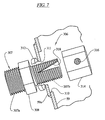
- FIG. 7 shows another nozzle 306.
- the nozzle 306 comprises a nozzle body 307 with a threaded tubular base portion 307a and one threaded provided tubular inner portion 307b, which by a Block 308 are separated by a wrench can attack.
- the base portion 307a takes a threaded one provided connection (not shown) with pressurized Air on.
- the inner portion 307b is through a hole 310 in the Unloading tube 59 inserted.
- the inner portion 307b extends also through a hole 311 in a mounting plate 59a is formed, which is welded onto the discharge tube 59.
- a lock nut 312 and a hexagonal cap 314 are screwed onto the inner section 307b around the nozzle 306 to clamp on the mounting plate 59a.
- the cap 314 includes an outlet opening 316 and inner portion 307b includes a triangular slot 318.
- Position of cap 314 along the length of the inner section 307b can be the effective size of the air opening inside the inner portion 307b set to the outlet opening 316 become.
- the locking nut 312 is then on the inside Section 307b positioned against the mounting plate 59 to clamp the cap 314.
- the orientation of the Exit opening 316 within the discharge tube 59 slightly can be changed by loosening the locking nut 312 and the nozzle body 307 is realigned.
- the compressed air cleaning system was connected to an unloading pipe Combine harvester of the applicant, type 9750 STS, tested one inner diameter of about 33 cm and a length of about 6 m Has.
- the distance of the nozzles 306 along the tube 59 was about 35 cm.
- the nozzles had orifices 316 with an effective one Diameter of about 2.4 mm at the angle G on the unloading tube 59 (see FIG. 4) of 45 degrees and with the angle H (see FIG. Figure 4) were directed downward from about 10 degrees.
- An inventive method for removing grain from an unloading tube 59 is provided which does the following Steps include: providing a variety of attached nozzles 106 or 306 within the discharge tube 59, the nozzles of the Pluralities are spaced longitudinally, and Use the nozzles by introducing air into the discharge tube 59 to grain along the unloading tube 59 and in and around the Unloading screw conveyor 57 around and out of the outlet 59a of the To promote discharge tube 59.
- the individual nozzles of the multitude can be sequential and in Groups A, B, C, D operated by nozzles in one direction along the discharge tube 59 from an upstream end near the right angle gear 57b toward the Outlet 59a of the discharge tube 59 to.
- each of the Groups operated for about 30 s to one ensure complete cleaning.
- the horizontal Section 57c is rotated slowly while the nozzles 106, 306 operated, d. H. Air flows at high speed in discharge the discharge tube 59.
Landscapes
- Engineering & Computer Science (AREA)
- Mechanical Engineering (AREA)
- Life Sciences & Earth Sciences (AREA)
- Environmental Sciences (AREA)
- Threshing Machine Elements (AREA)
- Cleaning In General (AREA)
Applications Claiming Priority (2)
| Application Number | Priority Date | Filing Date | Title |
|---|---|---|---|
| US309978 | 2002-12-04 | ||
| US10/309,978 US6736722B1 (en) | 2002-12-04 | 2002-12-04 | Unloader tube cleaning system for harvesting apparatus |
Publications (2)
| Publication Number | Publication Date |
|---|---|
| EP1425954A1 true EP1425954A1 (fr) | 2004-06-09 |
| EP1425954B1 EP1425954B1 (fr) | 2006-05-31 |
Family
ID=32298093
Family Applications (1)
| Application Number | Title | Priority Date | Filing Date |
|---|---|---|---|
| EP03027714A Expired - Lifetime EP1425954B1 (fr) | 2002-12-04 | 2003-12-02 | Dispositif de nettoyage pour un tube de décharge d'une machine de récolte |
Country Status (7)
| Country | Link |
|---|---|
| US (1) | US6736722B1 (fr) |
| EP (1) | EP1425954B1 (fr) |
| AR (1) | AR042271A1 (fr) |
| BR (1) | BR0305337B1 (fr) |
| CA (1) | CA2448608C (fr) |
| DE (1) | DE50303556D1 (fr) |
| DK (1) | DK1425954T3 (fr) |
Cited By (2)
| Publication number | Priority date | Publication date | Assignee | Title |
|---|---|---|---|---|
| EP1491082B2 (fr) † | 2003-06-25 | 2009-08-19 | CLAAS Selbstfahrende Erntemaschinen GmbH | Procédé pour le nettoyage des outils de travail dans une machine agricole |
| CN107950174A (zh) * | 2013-03-18 | 2018-04-24 | 株式会社久保田 | 联合收割机 |
Families Citing this family (6)
| Publication number | Priority date | Publication date | Assignee | Title |
|---|---|---|---|---|
| US7444183B2 (en) * | 2003-02-03 | 2008-10-28 | Enteromedics, Inc. | Intraluminal electrode apparatus and method |
| US20040172084A1 (en) * | 2003-02-03 | 2004-09-02 | Knudson Mark B. | Method and apparatus for treatment of gastro-esophageal reflux disease (GERD) |
| US8246751B2 (en) | 2010-10-01 | 2012-08-21 | General Electric Company | Pulsed detonation cleaning systems and methods |
| US9033643B1 (en) * | 2012-03-13 | 2015-05-19 | Ronald J. Kile | Combine harvester grain bulk tank unloading system |
| DE102017119377B3 (de) | 2017-08-24 | 2018-08-16 | Karl Schnell Gmbh & Co. Kg | Reinigungsvorrichtung und Verfahren zur Reinigung einer Förderschnecke |
| US10806077B2 (en) * | 2017-11-10 | 2020-10-20 | Deere & Company | Agricultural combine with electrostatic grain cleaner |
Citations (2)
| Publication number | Priority date | Publication date | Assignee | Title |
|---|---|---|---|---|
| DE449393C (de) * | 1925-12-11 | 1927-09-12 | Gotthilf Seitz | Einrichtung zum Foerdern von mehl- oder griessartigem Foerdergut mittels Durckluft |
| WO2002028751A1 (fr) * | 2000-10-04 | 2002-04-11 | Krämer Ag Bassersdorf | Convoyeur oscillant autonettoyant destine a ebavurer, depoussierer, et lever des elements de petite taille |
Family Cites Families (18)
| Publication number | Priority date | Publication date | Assignee | Title |
|---|---|---|---|---|
| US3880355A (en) | 1974-04-08 | 1975-04-29 | Graco Inc | Air blow gun |
| CA1132026A (fr) | 1979-08-13 | 1982-09-21 | Versatile Cornat Corporation | Moissonneuse rotative |
| US4397319A (en) | 1981-03-31 | 1983-08-09 | Deere & Company | Cleaning device for harvesting machines |
| US4400131A (en) | 1981-08-31 | 1983-08-23 | The Marmon Group, Inc. | Compressed air discharge system for trucks |
| US4594840A (en) | 1983-12-12 | 1986-06-17 | Sperry Corporation | Pneumatic system for combine header height control |
| US4688308A (en) | 1985-08-26 | 1987-08-25 | Alvarez Ramon A | Mobile radiator shop |
| EP0291582B1 (fr) | 1987-05-19 | 1991-12-11 | Ford New Holland N.V. | Appareil de nettoyage pour moissonneuse-batteuse |
| US5088960A (en) | 1991-03-15 | 1992-02-18 | Deere & Company | Air blast for cleaning axial separator |
| IT1249087B (it) | 1991-03-29 | 1995-02-11 | Josef Prenn | Dispositivo per la pulizia di filtri d'aria |
| GB2293080A (en) | 1994-09-17 | 1996-03-20 | New Holland Belguim Nv | Grain cleaner for combine harvester |
| US5546630A (en) | 1995-01-04 | 1996-08-20 | Long; Andre | Blast wiper for motor vehicle lights |
| US5507841A (en) | 1995-04-20 | 1996-04-16 | Uniwave, Inc. | Fan cleaner apparatus |
| DE19515895A1 (de) | 1995-04-29 | 1996-10-31 | Bosch Gmbh Robert | Druckluft-Versorgungseinrichtung für Fahrzeug-Druckluftanlagen sowie Verfahren zum Steuern der Druckluft-Versorgungseinrichtung |
| CA2182989C (fr) | 1995-09-01 | 2001-03-27 | Frederick William Nelson | Detecteur d'humidite pour le grain |
| US6058690A (en) | 1997-01-29 | 2000-05-09 | Rutt; Larry L. | Harvester |
| JPH11137064A (ja) | 1997-11-07 | 1999-05-25 | Mitsubishi Agricult Mach Co Ltd | コンバインにおける残留物除去システム |
| JP4331334B2 (ja) | 1999-07-21 | 2009-09-16 | セイレイ工業株式会社 | 穀粒収穫機における損失粒回収装置 |
| US6290361B1 (en) | 2000-11-01 | 2001-09-18 | Leonid Berzin | Universal clearing air system for windows and external mirrors of a vehicle |
-
2002
- 2002-12-04 US US10/309,978 patent/US6736722B1/en not_active Expired - Fee Related
-
2003
- 2003-11-07 CA CA002448608A patent/CA2448608C/fr not_active Expired - Fee Related
- 2003-11-27 BR BRPI0305337-7A patent/BR0305337B1/pt not_active IP Right Cessation
- 2003-12-02 AR ARP030104439A patent/AR042271A1/es active IP Right Grant
- 2003-12-02 DE DE50303556T patent/DE50303556D1/de not_active Expired - Lifetime
- 2003-12-02 EP EP03027714A patent/EP1425954B1/fr not_active Expired - Lifetime
- 2003-12-02 DK DK03027714T patent/DK1425954T3/da active
Patent Citations (2)
| Publication number | Priority date | Publication date | Assignee | Title |
|---|---|---|---|---|
| DE449393C (de) * | 1925-12-11 | 1927-09-12 | Gotthilf Seitz | Einrichtung zum Foerdern von mehl- oder griessartigem Foerdergut mittels Durckluft |
| WO2002028751A1 (fr) * | 2000-10-04 | 2002-04-11 | Krämer Ag Bassersdorf | Convoyeur oscillant autonettoyant destine a ebavurer, depoussierer, et lever des elements de petite taille |
Cited By (2)
| Publication number | Priority date | Publication date | Assignee | Title |
|---|---|---|---|---|
| EP1491082B2 (fr) † | 2003-06-25 | 2009-08-19 | CLAAS Selbstfahrende Erntemaschinen GmbH | Procédé pour le nettoyage des outils de travail dans une machine agricole |
| CN107950174A (zh) * | 2013-03-18 | 2018-04-24 | 株式会社久保田 | 联合收割机 |
Also Published As
| Publication number | Publication date |
|---|---|
| BR0305337B1 (pt) | 2011-01-11 |
| US20040110551A1 (en) | 2004-06-10 |
| US6736722B1 (en) | 2004-05-18 |
| BR0305337A (pt) | 2004-08-31 |
| EP1425954B1 (fr) | 2006-05-31 |
| DE50303556D1 (de) | 2006-07-06 |
| CA2448608A1 (fr) | 2004-06-04 |
| CA2448608C (fr) | 2007-06-19 |
| AU2003257873A1 (en) | 2004-06-24 |
| DK1425954T3 (da) | 2006-10-02 |
| AR042271A1 (es) | 2005-06-15 |
Similar Documents
| Publication | Publication Date | Title |
|---|---|---|
| DE60013772T2 (de) | Entlandungsmittel für dresch-und trennvorrichtungseinheit eines mähdreschers | |
| DE2948272C2 (fr) | ||
| EP0958733B1 (fr) | Rotor pour dispositif batteur-séparateur à écoulement axial | |
| EP1425952B1 (fr) | Dispositif de nettoyage pour un réservoir d'une machine de récolte | |
| EP2425725A1 (fr) | Appareil de lavage et/ou de rinçage de légumes ou de fruits non emballés | |
| DE69005290T2 (de) | Mähdrescher-Elevator zum Anschliessen der Mähwerksplattform an der Basis-Einheit. | |
| EP1236391A1 (fr) | Unité de traitement de récolte pour moissonneuse-batteuse | |
| DE3822689C2 (fr) | ||
| DE1945401A1 (de) | Selbstfahrender Maehdrescher mit Axialdreschmaschine | |
| EP1078568B1 (fr) | Dispositif pour le traitment de récolte pour une moissonneuse-batteuse | |
| EP1425954B1 (fr) | Dispositif de nettoyage pour un tube de décharge d'une machine de récolte | |
| DE2943838C2 (fr) | ||
| DE3533773A1 (de) | Selbstfahrender feldhaecksler | |
| EP1425953B1 (fr) | Machine de récolte avec convoyeur de décharge | |
| EP1226747A1 (fr) | Tambour avec éléments entraíneurs interchangeables | |
| DE102009002102A1 (de) | System zur Zugabe von Siliermittel für einen Feldhäcksler | |
| EP1806047B1 (fr) | Rotor d'un dispositif de traitement de récolte d'une moissonneuse-batteuse | |
| EP1425951B1 (fr) | Machine de récolte avec convoyeur de décharge | |
| EP1425950B1 (fr) | Réservoir et bouchon | |
| DE1929865A1 (de) | Duengemittel- bzw. Saatgutverteiler | |
| DE69423711T2 (de) | Landwirtschaftliche Maschine zur Verteilung von Viehfutter und/oder zum Stroheinstreu | |
| EP1151660B1 (fr) | Récolteuse en particulier faucheuse-hacheuse automotrice | |
| DE3023756A1 (de) | Selbstfahrender maehdrescher | |
| DD202487A5 (de) | Selbstfahrender maehdrescher | |
| DE102018219864B3 (de) | Mähdrescher mit einem Schneckenfördererzusammenbau |
Legal Events
| Date | Code | Title | Description |
|---|---|---|---|
| PUAI | Public reference made under article 153(3) epc to a published international application that has entered the european phase |
Free format text: ORIGINAL CODE: 0009012 |
|
| AK | Designated contracting states |
Kind code of ref document: A1 Designated state(s): AT BE BG CH CY CZ DE DK EE ES FI FR GB GR HU IE IT LI LU MC NL PT RO SE SI SK TR |
|
| AX | Request for extension of the european patent |
Extension state: AL LT LV MK |
|
| 17P | Request for examination filed |
Effective date: 20041209 |
|
| AKX | Designation fees paid |
Designated state(s): BE DE DK FR GB IT |
|
| GRAP | Despatch of communication of intention to grant a patent |
Free format text: ORIGINAL CODE: EPIDOSNIGR1 |
|
| GRAS | Grant fee paid |
Free format text: ORIGINAL CODE: EPIDOSNIGR3 |
|
| GRAA | (expected) grant |
Free format text: ORIGINAL CODE: 0009210 |
|
| AK | Designated contracting states |
Kind code of ref document: B1 Designated state(s): BE DE DK FR GB IT |
|
| REG | Reference to a national code |
Ref country code: GB Ref legal event code: FG4D Free format text: NOT ENGLISH |
|
| REF | Corresponds to: |
Ref document number: 50303556 Country of ref document: DE Date of ref document: 20060706 Kind code of ref document: P |
|
| GBT | Gb: translation of ep patent filed (gb section 77(6)(a)/1977) |
Effective date: 20060717 |
|
| REG | Reference to a national code |
Ref country code: DK Ref legal event code: T3 |
|
| ET | Fr: translation filed | ||
| PLBE | No opposition filed within time limit |
Free format text: ORIGINAL CODE: 0009261 |
|
| STAA | Information on the status of an ep patent application or granted ep patent |
Free format text: STATUS: NO OPPOSITION FILED WITHIN TIME LIMIT |
|
| 26N | No opposition filed |
Effective date: 20070301 |
|
| PGFP | Annual fee paid to national office [announced via postgrant information from national office to epo] |
Ref country code: GB Payment date: 20131227 Year of fee payment: 11 |
|
| PGFP | Annual fee paid to national office [announced via postgrant information from national office to epo] |
Ref country code: IT Payment date: 20131223 Year of fee payment: 11 Ref country code: FR Payment date: 20131217 Year of fee payment: 11 |
|
| GBPC | Gb: european patent ceased through non-payment of renewal fee |
Effective date: 20141202 |
|
| REG | Reference to a national code |
Ref country code: FR Ref legal event code: ST Effective date: 20150831 |
|
| PG25 | Lapsed in a contracting state [announced via postgrant information from national office to epo] |
Ref country code: GB Free format text: LAPSE BECAUSE OF NON-PAYMENT OF DUE FEES Effective date: 20141202 |
|
| PG25 | Lapsed in a contracting state [announced via postgrant information from national office to epo] |
Ref country code: FR Free format text: LAPSE BECAUSE OF NON-PAYMENT OF DUE FEES Effective date: 20141231 |
|
| PG25 | Lapsed in a contracting state [announced via postgrant information from national office to epo] |
Ref country code: IT Free format text: LAPSE BECAUSE OF NON-PAYMENT OF DUE FEES Effective date: 20141202 |
|
| PGFP | Annual fee paid to national office [announced via postgrant information from national office to epo] |
Ref country code: GB Payment date: 20180703 Year of fee payment: 11 |
|
| PGFP | Annual fee paid to national office [announced via postgrant information from national office to epo] |
Ref country code: BE Payment date: 20181227 Year of fee payment: 16 |
|
| REG | Reference to a national code |
Ref country code: DK Ref legal event code: EBP Effective date: 20191231 |
|
| REG | Reference to a national code |
Ref country code: BE Ref legal event code: MM Effective date: 20191231 |
|
| PG25 | Lapsed in a contracting state [announced via postgrant information from national office to epo] |
Ref country code: BE Free format text: LAPSE BECAUSE OF NON-PAYMENT OF DUE FEES Effective date: 20191231 |
|
| PG25 | Lapsed in a contracting state [announced via postgrant information from national office to epo] |
Ref country code: DK Free format text: LAPSE BECAUSE OF NON-PAYMENT OF DUE FEES Effective date: 20191231 |
|
| REG | Reference to a national code |
Ref country code: DE Ref legal event code: R084 Ref document number: 50303556 Country of ref document: DE |
|
| PGFP | Annual fee paid to national office [announced via postgrant information from national office to epo] |
Ref country code: DE Payment date: 20221121 Year of fee payment: 20 |
|
| REG | Reference to a national code |
Ref country code: DE Ref legal event code: R071 Ref document number: 50303556 Country of ref document: DE |