EP1426123B1 - Verfahren und Vorrichtung zum Innenhochdrukumformen - Google Patents
Verfahren und Vorrichtung zum Innenhochdrukumformen Download PDFInfo
- Publication number
- EP1426123B1 EP1426123B1 EP03025261A EP03025261A EP1426123B1 EP 1426123 B1 EP1426123 B1 EP 1426123B1 EP 03025261 A EP03025261 A EP 03025261A EP 03025261 A EP03025261 A EP 03025261A EP 1426123 B1 EP1426123 B1 EP 1426123B1
- Authority
- EP
- European Patent Office
- Prior art keywords
- profile
- contour
- walls
- sealing die
- sealing
- Prior art date
- Legal status (The legal status is an assumption and is not a legal conclusion. Google has not performed a legal analysis and makes no representation as to the accuracy of the status listed.)
- Expired - Lifetime
Links
- 238000000034 method Methods 0.000 title claims description 7
- 238000007789 sealing Methods 0.000 claims abstract description 46
- 238000007493 shaping process Methods 0.000 abstract 1
- 239000000463 material Substances 0.000 description 6
- 238000009825 accumulation Methods 0.000 description 4
- 230000035508 accumulation Effects 0.000 description 4
- 238000001125 extrusion Methods 0.000 description 2
- 229910000831 Steel Inorganic materials 0.000 description 1
- 238000011161 development Methods 0.000 description 1
- 230000018109 developmental process Effects 0.000 description 1
- 238000004519 manufacturing process Methods 0.000 description 1
- 238000005192 partition Methods 0.000 description 1
- 239000010959 steel Substances 0.000 description 1
- 230000007704 transition Effects 0.000 description 1
Images


Classifications
-
- B—PERFORMING OPERATIONS; TRANSPORTING
- B21—MECHANICAL METAL-WORKING WITHOUT ESSENTIALLY REMOVING MATERIAL; PUNCHING METAL
- B21D—WORKING OR PROCESSING OF SHEET METAL OR METAL TUBES, RODS OR PROFILES WITHOUT ESSENTIALLY REMOVING MATERIAL; PUNCHING METAL
- B21D3/00—Straightening or restoring form of metal rods, metal tubes, metal profiles, or specific articles made therefrom, whether or not in combination with sheet metal parts
-
- B—PERFORMING OPERATIONS; TRANSPORTING
- B21—MECHANICAL METAL-WORKING WITHOUT ESSENTIALLY REMOVING MATERIAL; PUNCHING METAL
- B21D—WORKING OR PROCESSING OF SHEET METAL OR METAL TUBES, RODS OR PROFILES WITHOUT ESSENTIALLY REMOVING MATERIAL; PUNCHING METAL
- B21D26/00—Shaping without cutting otherwise than using rigid devices or tools or yieldable or resilient pads, i.e. applying fluid pressure or magnetic forces
- B21D26/02—Shaping without cutting otherwise than using rigid devices or tools or yieldable or resilient pads, i.e. applying fluid pressure or magnetic forces by applying fluid pressure
- B21D26/033—Deforming tubular bodies
- B21D26/045—Closing or sealing means
Definitions
- the invention relates to a method for hydroforming a profile with the features of the preamble of claim 1 and a device having the features of the preamble of claim 4.
- Such a method and such a device are known from DE 3 923 358 A1 or US 4 414 034 A known.
- sealing stamps are pressed in front of the profile on both sides radially in the profile extension direction. These seals have a sealing edge against which the profile applies.
- the sealing edge of the sealing punch is made of wear-resistant material and lies under a relatively high pressure in front of the wall of the profile.
- EP 1 388 381 B1 published after the filing date of the present application, discloses a device for hydroforming of hollow bodies which comprises an at least two-part tool and this axial cylinder assigned on both sides.
- the axial cylinders sealingly seal a double-chamber profile with sealing punches, wherein the sealing punches have a groove into which the central web of the double-chamber profile dips.
- the sealing dies are divided into two adjacent on a common support plate punch heads, and at least one sealing stamp has a connected to a pressure medium source high-pressure bore.
- the sealing punch is designed as a steel punch with a on the support plate in the transition to the foot of the recessed in relation to the outer edge of the support plate inwardly punch heads corresponding to the contour of the punch heads circumferential sealing edge.
- the sealing edge has in the groove base at each of the beginnings of the groove accumulation of material.
- the accumulation of material on the end face of the sealing ram is formed so that on the end face of the double-chamber profile, a recess must be present, in which the material accumulations of the sealing ram can retract when moving the sealing ram.
- an additional, separate to the actual hydroforming separate processing step is required to form on the double-chamber profile required for receiving the material accumulations recesses.
- the invention has for its object to find a method and apparatus for hydroforming of profiles with in addition to the main contour inwardly or outwardly projecting walls or chambers, in which the seal is subject to low wear and / or in which the additional walls or chambers only bent or bulged at its outer end.
- a typical extruded profile is shown, which is to be formed by means of internal high pressure.
- This profile has a circumferential main contour 1.
- the main contour 1 is connected by two walls 2, 3, so that three chambers 4, 5, 6 arise.
- the profile is completed by a wall 7 protruding outwards from the main contour 1.
- sealing stamps 8 are used at both ends of the profile, which are pressed in the forming press radially in front of the ends of the profiles.
- the shape of the sealing edge 9 of the sealing stamp corresponds to the shape of the profile.
- the sealing edge 9 is formed by the surface of the sealing washer 10.
- Guide pieces 11, 12, 13 correspond approximately to the shape of the chambers 4, 5, 6 and dive in the ancestor of the sealing ram 8 against the profile in the chambers 4, 5, 6 a.
- the sealing disk 10 and the guide pieces 11, 12, 13 are connected by suitable, only schematically illustrated fastening means 14, 15, 16 with the sealing ram 8. These fastening means 14, 15, 16 can also allow the supply of the forming medium.
- slots 17 which extend approximately in continuation of the inner contour 18 or outer contour of the main contour 1.
- the slot 17 is slightly adjacent to the inner contour 18 of the main contour 1 of the profile.
- the slots are preferably generated when the sealing ram 8 moves together by a correspondingly formed tool contour on the sealing ram 8.
- FIG. 1 An alternative or additional solution to the problem underlying the invention is shown in FIG.
- the sealing disc 10 is formed in the extension region of the main contour 1 connecting walls 2, 3 with grooves 19. These grooves 19 allow axial elongation of the walls 2, 3 in the high pressure forming of the overall profile. By this measure it is achieved that the walls 2, 3 do not buckle. Since the wall 7, which projects from the main contour 1 to the outside, is not supported by the sealing ram 8, but projects freely to the outside, the above measure for this wall 7 is of course not required. It is essential, however, that the grooves 19 do not extend to the sealing edge 9 of the main contour 1, so that a clear circumferential seal of the overall profile is guaranteed.
Landscapes
- Engineering & Computer Science (AREA)
- Mechanical Engineering (AREA)
- Physics & Mathematics (AREA)
- Fluid Mechanics (AREA)
- Shaping Metal By Deep-Drawing, Or The Like (AREA)
- Inorganic Compounds Of Heavy Metals (AREA)
- Blow-Moulding Or Thermoforming Of Plastics Or The Like (AREA)
- Press Drives And Press Lines (AREA)
- Building Environments (AREA)
Description
- Die Erfindung betrifft ein Verfahren zum Innenhochdruckumformen eines Profils mit den Merkmalen des Oberbegriffs des Anspruchs 1 und eine Vorrichtung mit den Merkmalen des Oberbegriffs des Anspruchs 4. Ein solches Verfahren und eine solche Vorrichtung sind aus der DE 3 923 358 A1 oder der US 4 414 034 A bekannt.
- Zum Innenhochdruckumformen werden nicht nur Rohre als Ausgangswerkstücke eingesetzt, wie dieses beispielsweise aus der DE 39 23 358 A1 und der US 4,414,834 A bekannt ist. Es werden auch Profile eingesetzt, die eine profilierte Mantelform aufweisen. Häufig werden diese Profile durch Strangpressen hergestellt.
- Um eine einwandfreie Abdichtung zu ermöglichen, werden beidseitig radial in Profilerstreckungsrichtung Dichtstempel vor das Profil gepresst. Diese Dichtstempel haben eine Dichtkante, gegen die sich das Profil anlegt. Um den Stempelverschleiß so gering wie möglich zu halten, ist die Dichtkante des Dichtstempels aus verschleißfestem Material hergestellt und legt sich unter einem relativ hohen Druck vor die Wand des Profils.
- Es besteht der Wunsch, auch Profile mit Innenhochdruck umzuformen, die zusätzlich zur Hauptkontur eine oder mehrere sich nach innen oder außen ragende Wände oder Kammern aufweisen. Nachteilig beim Umformen derartiger Profile verformen sich die zusätzlichen Kammern oder Wände auch axial unterschiedlich zur Hauptkontur. Das bedingt bei der Verwendung von Dichtkanten, dass die Gefahr besteht, dass diese in axialer Richtung undefiniert ausknicken oder ausbeulen. Bei der Verwendung von weicheren Materialien an der Dichtkante kann zwar die unterschiedliche Längung der Wände oder Kammern in axialer Richtung ausgeglichen werden. Es besteht jedoch der Nachteil eines hohen Verschleißes der Dichtkante.
- Aus der nach dem Anmeldetag der vorliegenden Anmeldung veröffentlichten EP 1 388 381 B1 ist eine Vorrichtung zur Innenhochdruckumformung von Hohlkörpern bekannt, die ein mindestens zweiteiliges Werkzeug und diesem an beiden Seiten zugeordnete Axialzylinder umfasst. Die Axialzylinder verschließen mit Dichtstempeln dichtend ein Doppelkammerprofil, wobei die Dichtstempel eine Nut aufweisen, in die der Mittelsteg des Doppelkammerprofils eintaucht. Die Dichtstempel sind dabei in zwei auf einer gemeinsamen Trägerplatte nebeneinander liegende Stempelköpfe unterteilt, und zumindest ein Dichtstempel weist eine an eine Druckmittelquelle angeschlossene Hochdruckbohrung auf. Der Dichtstempel ist dabei als Stahlstempel mit einer auf der Trägerplatte im Übergang zum Fußbereich der in Bezug auf die Außenkante der Trägerplatte nach innen zurückversetzten Stempelköpfe entsprechend der Kontur der Stempelköpfe umlaufenden Dichtkante ausgebildet. Die Dichtkante weist im Nutgrund an jeweils den Anfängen der Nut eine Materialanhäufung auf. Dabei ist die Materialanhäufung an der Stirnseite des Dichtstempels so ausgebildet, dass an der Stirnseite des Doppelkammerprofils eine Ausnehmung vorhanden sein muss, in die die Materialanhäufungen des Dichtstempels beim Zusammenfahren der Dichtstempel einfahren können. Somit ist ein zusätzlicher, dem eigentlichen Innenhochdruckumformen vorgeschalteter separater Bearbeitungsschritt erforderlich, um an dem Doppelkammerprofil die zur Aufnahme der Materialanhäufungen erforderlichen Ausnehmungen auszubilden.
- Der Erfindung liegt die Aufgabe zugrunde, ein Verfahren und eine Vorrichtung zum Innenhochdruckumformen von Profilen mit zusätzlich zur Hauptkontur nach innen oder nach außen ragenden Wänden oder Kammern zu finden, bei dem der Dichtstempel einem geringen Verschleiß unterliegt und/oder bei dem die zusätzlichen Wände oder Kammern nur an ihrem äußeren Ende abgeknickt oder ausgebeult werden.
- Diese Aufgabe wird erfindungsgemäß mit den Merkmalen des Anspruchs 1 und/oder des Anspruchs 4 gelöst. Vorteilhafte Aus- und Weiterbildungen sind in den Ansprüchen 2 und 3 sowie 5 bis 6 beschrieben.
- Die mit der Erfindung erzielten Vorteile bestehen insbesondere darin, dass vielgestaltige Strangpressprofile mit Zwischenwänden und Zwischenkammern durch Innenhochdruck umgeformt werden können, wobei eine wirtschaftliche Fertigung gegeben ist. Diese Profile werden an ihren Enden nur geringförmig umgeformt, sodass bei der nachfolgenden Bearbeitung der Profile die Enden gar nicht oder nur ein geringes Maß der Enden abgeschnitten werden müssen.
- Ein Ausführungsbeispiel der Erfindung ist in der Zeichnung dargestellt und wird im Folgenden näher beschrieben. Es zeigen
- Fig. 1
- die Draufsicht auf das Ende eines Mehrkammerstrangpressprofiles,
- Fig. 2
- eine vergrößerte Darstellung des Details II in Fig. 1,
- Fig. 3
- einen Dichtstempel zum Abdichten des Endes des Profils gemäß Fig. 1 und
- Fig. 4
- eine vergrößerte Darstellung der Einzelheit IV in Fig. 3.
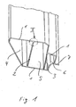
- In Fig. 1 wird ein typisches Strangpressprofil gezeigt, das mittels Innenhochdruck umgeformt werden soll. Dieses Profil weist eine umlaufende Hauptkontur 1 auf. Die Hauptkontur 1 wird durch zwei Wände 2, 3 verbunden, sodass drei Kammern 4, 5, 6 entstehen. Das Profil wird vervollständigt durch eine von der Hauptkontur 1 nach außen ragende Wand 7.
- Zum Abdichten der Stirnfläche des Profils beim Innenhochdruckumformen werden an beiden Enden des Profils Dichtstempel 8 verwendet, die in der Umformpresse radial vor die Enden der Profile gepresst werden. Die Form der Dichtkante 9 der Dichtstempel entspricht der Form des Profils. Die Dichtkante 9 wird durch die Oberfläche der Dichtscheibe 10 gebildet. Diese Dichtscheibe 10 liegt abschließend vor dem Dichtstempel 8. Führungsstücke 11, 12, 13 entsprechen etwa der Form der Kammern 4, 5, 6 und tauchen beim Vorfahren des Dichtstempels 8 gegen das Profil in die Kammern 4, 5, 6 ein. Dadurch sind die Wände 2, 3 sowie die Hauptkontur 1 radial gehalten, wodurch auch das gesamte Profil gegenüber dem Dichtstempel 8 geführt und gehalten ist. Die Dichtscheibe 10 sowie die Führungsstücke 11, 12, 13 werden durch geeignete, nur schematisch dargestellte Befestigungsmittel 14, 15, 16 mit dem Dichtstempel 8 verbunden. Diese Befestigungsmittel 14, 15, 16 können auch die Zuleitung des Umformmediums ermöglichen.
- Um ein definiertes Ausbeulen oder Ausknicken der Wände 2, 3, 7 zu ermöglichen, sind diese mit Schlitzen 17 ausgebildet, die sich etwa in Fortsetzung der Innenkontur 18 oder Außenkontur der Hauptkontur 1 erstrecken. Im Ausführungsbeispiel liegt der Schlitz 17 geringfügig neben der Innenkontur 18 der Hauptkontur 1 des Profils. Die Schlitze werden vorzugsweise beim Zusammenfahren der Dichtstempel 8 durch eine entsprechend ausgebildete Werkzeugkontur am Dichtstempel 8 erzeugt.
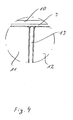
- Eine alternative oder zusätzliche Lösung der der Erfindung zugrunde liegenden Aufgabe wird in Fig. 4 gezeigt. Die Dichtscheibe 10 ist im Erstreckungsbereich der die Hauptkontur 1 verbindenden Wände 2, 3 mit Nuten 19 ausgebildet. Diese Nuten 19 ermöglichen eine axiale Längung der Wände 2, 3 bei der Hochdruckumformung des Gesamtprofils. Durch diese Maßnahme wird erreicht, dass die Wände 2, 3 nicht ausknicken. Da die Wand 7, die von der Hauptkontur 1 nach außen ragt, nicht vom Dichtstempel 8 abgestützt wird, sondern frei nach außen ragt, ist die vorbeschriebene Maßnahme für diese Wand 7 selbstverständlich nicht erforderlich. Wesentlich ist jedoch, dass die Nuten 19 sich nicht bis zur Dichtkante 9 der Hauptkontur 1 erstrecken, damit eine eindeutige umlaufende Abdichtung des Gesamtprofils gewährleistet ist.
-
- 1.
- Hauptkontur
- 2.
- Wand
- 3.
- Wand
- 4.
- Kammer
- 5.
- Kammer
- 6.
- Kammer
- 7.
- Wand
- 8.
- Dichtstempel
- 9.
- Dichtkante
- 10.
- Dichtscheibe
- 11.
- Führungsstück
- 12.
- Führungsstück
- 13.
- Führungsstück
- 14.
- Befestigungsmittel
- 15.
- Befestigungsmittel
- 16.
- Befestigungsmittel
- 17.
- Schlitz
- 18.
- Innenkontur
- 19.
- Nut
Claims (6)
- Verfahren zum Innenhochdruckumformen eines Profils mit einer umlaufenden Hauptkontur (1), wobei ein Dichtstempel (8) in Profilerstreckungsrichtung radial vor das Profil gepresst wird, dadurch gekennzeichnet, bei einem Profil, das zusätzlich zur Hauptkontur (1) eine oder mehrere nach innen oder nach außen ragende Wände (2, 3, 7) oder Kammern (4, 5, 6) aufweist, der Dichtstempel (8) das Profil nur an der Hauptkontur (1) abdichtet, und dass an den Stirnflächen des Profils die Wände (7) oder Wände (2, 3) der Kammern (4, 5, 6) mit Schlitzen (17) versehen sind, die etwa in Fortsetzung der Innenkontur (18) und/oder Außenkontur der Hauptkontur (1) verlaufen, wobei die Schlitze (17) beim Pressen des Dichtstempels (8) gegen das Profil durch eine entsprechend ausgebildete Werkzeugkontur am Dichtstempel (8) erzeugt werden.
- Verfahren nach Anspruch 1, dadurch gekennzeichnet, dass die Schlitze (17) eine Tiefe von weniger als 1 cm aufweisen.
- Verfahren nach Anspruch 2 oder Anspruch 3, dadurch gekennzeichnet, dass bei Profilen, die mehrere Kammern (4, 5, 6) aufweisen, Schlitze (17) auch an den Kreuzungspunkten und Wandabzweigungen der Zwischenwände angeordnet sind.
- Vorrichtung zum Innenhochdruckumformen eines Profils mit einer umlaufenden Hauptkontur (1), wobei ein Dichtstempel (8) in Profilerstreckungsrichtung radial vor das Profil gepresst wird, dadurch gekennzeichnet, bei einem Profil, das zusätzlich zur Hauptkontur (1) eine oder mehrere nach innen oder nach außen ragende Wände (2, 3, 7) oder Kammern (4, 5, 6) aufweist, der Dichtstempel (8) das Profil nur an der Hauptkontur (1) abdichtet, wobei der Dichtstempel (8) mit Nuten (19) entsprechend der Form dieser zusätzlichen Wände (2, 3, 7) anschließend an diese ausgebildet ist, und wobei die Nuten (19) sich annähernd bis an den Rand der Hauptkontur (1) erstrecken, und dass die Werkzeugkontur am Dichtstempel (8) derart ausgebildet ist, dass beim Pressen des Dichtstempels (8) gegen das Profil beabstandet zur Hauptkontur (1) angeordnete Schlitze (17) in den Wänden (2, 3, 7) erzeugt werden.
- Vorrichtung nach Anspruch 4, dadurch gekennzeichnet, dass die Nuten (19) eine Tiefe von weniger als 1 cm aufweisen.
- Vorrichtung nach Anspruch 4 oder 5, dadurch gekennzeichnet, dass bei Profilen, die mehrere Kammern (4, 5, 6) aufweisen, Nuten (19) auch an den Kreuzungspunkten und Wandabzweigungen der Zwischenwände angeordnet sind.
Priority Applications (1)
| Application Number | Priority Date | Filing Date | Title |
|---|---|---|---|
| SI200330695T SI1426123T1 (sl) | 2002-12-06 | 2003-11-06 | Postopek in naprava za visokotlačno oblikovanje notranjosti profila |
Applications Claiming Priority (4)
| Application Number | Priority Date | Filing Date | Title |
|---|---|---|---|
| DE10257343 | 2002-12-06 | ||
| DE2002157343 DE10257343C1 (de) | 2002-12-06 | 2002-12-06 | Verfahren zum Innenhochdruckumformen |
| DE20307400U | 2003-05-13 | ||
| DE20307400U DE20307400U1 (de) | 2003-05-13 | 2003-05-13 | Dichtstempel zum Abdichten beim Innenhochdruckumformen |
Publications (3)
| Publication Number | Publication Date |
|---|---|
| EP1426123A2 EP1426123A2 (de) | 2004-06-09 |
| EP1426123A3 EP1426123A3 (de) | 2005-10-19 |
| EP1426123B1 true EP1426123B1 (de) | 2007-02-28 |
Family
ID=32313577
Family Applications (1)
| Application Number | Title | Priority Date | Filing Date |
|---|---|---|---|
| EP03025261A Expired - Lifetime EP1426123B1 (de) | 2002-12-06 | 2003-11-06 | Verfahren und Vorrichtung zum Innenhochdrukumformen |
Country Status (7)
| Country | Link |
|---|---|
| US (1) | US7028520B2 (de) |
| EP (1) | EP1426123B1 (de) |
| AT (1) | ATE355141T1 (de) |
| CA (1) | CA2449626C (de) |
| DE (1) | DE50306648D1 (de) |
| ES (1) | ES2281592T3 (de) |
| SI (1) | SI1426123T1 (de) |
Cited By (2)
| Publication number | Priority date | Publication date | Assignee | Title |
|---|---|---|---|---|
| DE102024120770A1 (de) * | 2024-07-22 | 2026-01-22 | Thyssenkrupp Ag | Dichtstempel, Vorrichtung und Verfahren zum Innenhochdruckumformen |
| DE102024120773B3 (de) * | 2024-07-22 | 2026-01-22 | Thyssenkrupp Ag | Dichtstempel, Vorrichtung und Verfahren zum Innenhochdruckumformen |
Families Citing this family (2)
| Publication number | Priority date | Publication date | Assignee | Title |
|---|---|---|---|---|
| US7975383B2 (en) * | 2006-07-28 | 2011-07-12 | Ford Global Technologies, Llc | Double hydroformed tube with integral reinforcement |
| EP2076756A2 (de) * | 2006-10-12 | 2009-07-08 | Koninklijke Philips Electronics N.V. | Erkennung eines umgebungszustandes mit vollständig integriertem wandler auf hydrogelbasis |
Citations (1)
| Publication number | Priority date | Publication date | Assignee | Title |
|---|---|---|---|---|
| EP1388381A1 (de) * | 2002-08-08 | 2004-02-11 | Schuler Hydroforming GmbH & Co. KG | Vorrichtung zur Innenhochdruck-Umformung von Hohlkörpern |
Family Cites Families (10)
| Publication number | Priority date | Publication date | Assignee | Title |
|---|---|---|---|---|
| US2837810A (en) * | 1955-06-17 | 1958-06-10 | Flexonics Corp | Method of producing fittings |
| US3180011A (en) * | 1960-09-01 | 1965-04-27 | Olin Mathieson | Hollow article manufacture by fluid pressure |
| US4414834A (en) * | 1981-02-05 | 1983-11-15 | Carrier Corporation | Method for expanding tubular blanks |
| IT1226921B (it) * | 1988-07-15 | 1991-02-22 | Renato Beretta | Procedimento e pressa per realizzare corpi tubolari sagomati a freddo. |
| US5233856A (en) * | 1992-05-29 | 1993-08-10 | General Motors Corporation | External seal unit for tube hydroforming |
| US5349839A (en) * | 1993-04-05 | 1994-09-27 | Aluminum Company Of America | Flexible constraining apparatus and method for the stretch forming of elongated hollow metal sections |
| US5363544A (en) * | 1993-05-20 | 1994-11-15 | Benteler Industries, Inc. | Multi-stage dual wall hydroforming |
| US5644829A (en) * | 1993-08-16 | 1997-07-08 | T I Corporate Services Limited | Method for expansion forming of tubing |
| DE19742443C2 (de) * | 1997-09-26 | 1999-07-22 | Daimler Chrysler Ag | Vorrichtung zum Innenhochdruckumformen von Hohlprofilen |
| DE19946011A1 (de) * | 1999-08-05 | 2001-02-08 | Alusuisse Tech & Man Ag | Verfahren zum Umformen eines Ausgangsprofils od. dgl. Werkstücks mittels eines Innenhochdruckes sowie Profil dafür |
-
2003
- 2003-11-06 EP EP03025261A patent/EP1426123B1/de not_active Expired - Lifetime
- 2003-11-06 SI SI200330695T patent/SI1426123T1/sl unknown
- 2003-11-06 AT AT03025261T patent/ATE355141T1/de not_active IP Right Cessation
- 2003-11-06 DE DE50306648T patent/DE50306648D1/de not_active Expired - Lifetime
- 2003-11-06 ES ES03025261T patent/ES2281592T3/es not_active Expired - Lifetime
- 2003-11-10 US US10/705,488 patent/US7028520B2/en not_active Expired - Fee Related
- 2003-11-17 CA CA002449626A patent/CA2449626C/en not_active Expired - Lifetime
Patent Citations (1)
| Publication number | Priority date | Publication date | Assignee | Title |
|---|---|---|---|---|
| EP1388381A1 (de) * | 2002-08-08 | 2004-02-11 | Schuler Hydroforming GmbH & Co. KG | Vorrichtung zur Innenhochdruck-Umformung von Hohlkörpern |
Cited By (2)
| Publication number | Priority date | Publication date | Assignee | Title |
|---|---|---|---|---|
| DE102024120770A1 (de) * | 2024-07-22 | 2026-01-22 | Thyssenkrupp Ag | Dichtstempel, Vorrichtung und Verfahren zum Innenhochdruckumformen |
| DE102024120773B3 (de) * | 2024-07-22 | 2026-01-22 | Thyssenkrupp Ag | Dichtstempel, Vorrichtung und Verfahren zum Innenhochdruckumformen |
Also Published As
| Publication number | Publication date |
|---|---|
| ATE355141T1 (de) | 2006-03-15 |
| DE50306648D1 (de) | 2007-04-12 |
| CA2449626C (en) | 2008-08-12 |
| US20040194523A1 (en) | 2004-10-07 |
| SI1426123T1 (sl) | 2007-06-30 |
| ES2281592T3 (es) | 2007-10-01 |
| US7028520B2 (en) | 2006-04-18 |
| CA2449626A1 (en) | 2004-06-06 |
| EP1426123A3 (de) | 2005-10-19 |
| EP1426123A2 (de) | 2004-06-09 |
Similar Documents
| Publication | Publication Date | Title |
|---|---|---|
| EP0747614B1 (de) | Metallische Zylinderkopfdichtung | |
| DE2747382C2 (de) | Verfahren zur Herstellung eines einen hohlzylindrischen Teil aufweisenden Flanschstückes und Vorrichtung zur Durchführung des Verfahrens | |
| EP1963690B1 (de) | Schraubmutter, verfahren zu ihrer herstellung und wekzeug dafür | |
| DE2557764B2 (de) | Verfahren und Vorrichtung zur Formung eines Tiefbettfelgenrohlings | |
| DE102014221878A1 (de) | Pressenwerkzeug zum Herstellen eines wenigstens eine scharfkantige Blechformteilkante aufweisenden Blechformteils und hiermit hergestelltes Blechformteil | |
| DE19842750B4 (de) | Verfahren und Herstellung von tiefgezogenen Hohlteilen und Ziehwerkzeug | |
| DE3716176A1 (de) | Verfahren und vorrichtung zum umformen von hohlkoerpern sowie verwendung des verfahrens bzw. der vorrichtung und dosenkoerper | |
| DE3739425A1 (de) | Dichtungsanordnung sowie verfahren zu ihrer herstellung | |
| DE19751293A1 (de) | Einschichtige oder mehrschichtige Metallzylinderkopfdichtung und Verfahren zu ihrer Herstellung | |
| DE2806094C2 (de) | Dünnwandiges Beschlagteil aus Metall sowie Verfahren und Werkzeug zu seiner Herstellung | |
| DE10337383B4 (de) | Verfahren zum Innenhochdruckumformen von konischen Rohren aus Metall | |
| DE102018131967A1 (de) | Verfahren zum Kalibrieren eines gekrümmten metallischen Hohlkammerprofils | |
| EP1426123A2 (de) | Verfahren und Vorrichtung zum Innenhochdrukumformen | |
| DE10257343C1 (de) | Verfahren zum Innenhochdruckumformen | |
| EP1646461A1 (de) | Verfahren und vorrichtung zur bearbeitung von randbereichen von zylindrischen hohlkörpern | |
| DE102013104269A1 (de) | Metallische Flachdichtung sowie Verfahren zu deren Herstellung | |
| DE20307400U1 (de) | Dichtstempel zum Abdichten beim Innenhochdruckumformen | |
| DE3906958A1 (de) | Verfahren zur herstellung von flachen bauteilen | |
| DE2507511C2 (de) | Verfahren zur Herstellung von Spültischabdeckungen mit wenigstens einem Becken durch Tiefziehen und Vorrichtung zur Durchführung des Verfahrens | |
| DE102005050202B4 (de) | Blechteil mit partiellen Verstärkungselementen hergestellt nach dem Außenhochdruckumformverfahren | |
| WO2002034428A1 (de) | Verfahren zur herstellung von flanschplatten sowie flanschplatte | |
| DE19706218C2 (de) | Verfahren zum Formen eines gebogenen Bauteils im Rahmen der Innenhochdruck-Umformtechnik und Vorrichtung für die Durchführung des Verfahrens | |
| EP1741497B9 (de) | Verfahren und Werkzeug zur spanlosen Herstellung von Werkstücken mit einer Kerbe und Werkstück mit einer Kerbe | |
| DE10236296A1 (de) | Vorrichtung zur Innenhochdruck-Umformung von Hohlkörpern | |
| DE10343135B4 (de) | Verfahren zur Herstellung eines umfänglich geschlossenen Hohlprofiles |
Legal Events
| Date | Code | Title | Description |
|---|---|---|---|
| PUAI | Public reference made under article 153(3) epc to a published international application that has entered the european phase |
Free format text: ORIGINAL CODE: 0009012 |
|
| AK | Designated contracting states |
Kind code of ref document: A2 Designated state(s): AT BE BG CH CY CZ DE DK EE ES FI FR GB GR HU IE IT LI LU MC NL PT RO SE SI SK TR |
|
| AX | Request for extension of the european patent |
Extension state: AL LT LV MK |
|
| PUAL | Search report despatched |
Free format text: ORIGINAL CODE: 0009013 |
|
| AK | Designated contracting states |
Kind code of ref document: A3 Designated state(s): AT BE BG CH CY CZ DE DK EE ES FI FR GB GR HU IE IT LI LU MC NL PT RO SE SI SK TR |
|
| AX | Request for extension of the european patent |
Extension state: AL LT LV MK |
|
| 17P | Request for examination filed |
Effective date: 20051110 |
|
| AKX | Designation fees paid |
Designated state(s): AT BE CH CZ DE ES FR GB IT LI NL SE SI |
|
| 17Q | First examination report despatched |
Effective date: 20060130 |
|
| GRAP | Despatch of communication of intention to grant a patent |
Free format text: ORIGINAL CODE: EPIDOSNIGR1 |
|
| GRAS | Grant fee paid |
Free format text: ORIGINAL CODE: EPIDOSNIGR3 |
|
| GRAA | (expected) grant |
Free format text: ORIGINAL CODE: 0009210 |
|
| AK | Designated contracting states |
Kind code of ref document: B1 Designated state(s): AT BE CH CZ DE ES FR GB IT LI NL SE SI |
|
| REG | Reference to a national code |
Ref country code: GB Ref legal event code: FG4D Free format text: NOT ENGLISH |
|
| REG | Reference to a national code |
Ref country code: SE Ref legal event code: TRGR |
|
| GBT | Gb: translation of ep patent filed (gb section 77(6)(a)/1977) |
Effective date: 20070228 |
|
| REG | Reference to a national code |
Ref country code: CH Ref legal event code: EP |
|
| REF | Corresponds to: |
Ref document number: 50306648 Country of ref document: DE Date of ref document: 20070412 Kind code of ref document: P |
|
| ET | Fr: translation filed | ||
| REG | Reference to a national code |
Ref country code: ES Ref legal event code: FG2A Ref document number: 2281592 Country of ref document: ES Kind code of ref document: T3 |
|
| REG | Reference to a national code |
Ref country code: CH Ref legal event code: NV Representative=s name: BOVARD AG PATENTANWAELTE Ref country code: CH Ref legal event code: PUE Owner name: THYSSENKRUPP TECHNOLOGIES AG Free format text: THYSSENKRUPP AUTOMOTIVE AG#ALLEESTRASSE 165#44793 BOCHUM (DE) -TRANSFER TO- THYSSENKRUPP TECHNOLOGIES AG#AM THYSSENHAUS 1#45128 ESSEN (DE) |
|
| PLBE | No opposition filed within time limit |
Free format text: ORIGINAL CODE: 0009261 |
|
| STAA | Information on the status of an ep patent application or granted ep patent |
Free format text: STATUS: NO OPPOSITION FILED WITHIN TIME LIMIT |
|
| 26N | No opposition filed |
Effective date: 20071129 |
|
| PGFP | Annual fee paid to national office [announced via postgrant information from national office to epo] |
Ref country code: CH Payment date: 20081114 Year of fee payment: 6 Ref country code: CZ Payment date: 20081030 Year of fee payment: 6 Ref country code: NL Payment date: 20081113 Year of fee payment: 6 |
|
| PGFP | Annual fee paid to national office [announced via postgrant information from national office to epo] |
Ref country code: AT Payment date: 20081114 Year of fee payment: 6 |
|
| PGFP | Annual fee paid to national office [announced via postgrant information from national office to epo] |
Ref country code: SI Payment date: 20081103 Year of fee payment: 6 |
|
| REG | Reference to a national code |
Ref country code: NL Ref legal event code: V1 Effective date: 20100601 |
|
| REG | Reference to a national code |
Ref country code: CH Ref legal event code: PL |
|
| REG | Reference to a national code |
Ref country code: SI Ref legal event code: KO00 Effective date: 20100614 |
|
| PG25 | Lapsed in a contracting state [announced via postgrant information from national office to epo] |
Ref country code: CZ Free format text: LAPSE BECAUSE OF NON-PAYMENT OF DUE FEES Effective date: 20091106 Ref country code: SI Free format text: LAPSE BECAUSE OF NON-PAYMENT OF DUE FEES Effective date: 20091107 Ref country code: AT Free format text: LAPSE BECAUSE OF NON-PAYMENT OF DUE FEES Effective date: 20091106 |
|
| PG25 | Lapsed in a contracting state [announced via postgrant information from national office to epo] |
Ref country code: NL Free format text: LAPSE BECAUSE OF NON-PAYMENT OF DUE FEES Effective date: 20100601 Ref country code: LI Free format text: LAPSE BECAUSE OF NON-PAYMENT OF DUE FEES Effective date: 20091130 Ref country code: CH Free format text: LAPSE BECAUSE OF NON-PAYMENT OF DUE FEES Effective date: 20091130 |
|
| PGFP | Annual fee paid to national office [announced via postgrant information from national office to epo] |
Ref country code: BE Payment date: 20131121 Year of fee payment: 11 Ref country code: ES Payment date: 20131128 Year of fee payment: 11 |
|
| PG25 | Lapsed in a contracting state [announced via postgrant information from national office to epo] |
Ref country code: BE Free format text: LAPSE BECAUSE OF NON-PAYMENT OF DUE FEES Effective date: 20141130 |
|
| REG | Reference to a national code |
Ref country code: FR Ref legal event code: PLFP Year of fee payment: 13 |
|
| REG | Reference to a national code |
Ref country code: ES Ref legal event code: FD2A Effective date: 20151230 |
|
| PG25 | Lapsed in a contracting state [announced via postgrant information from national office to epo] |
Ref country code: ES Free format text: LAPSE BECAUSE OF NON-PAYMENT OF DUE FEES Effective date: 20141107 |
|
| REG | Reference to a national code |
Ref country code: FR Ref legal event code: PLFP Year of fee payment: 14 |
|
| REG | Reference to a national code |
Ref country code: FR Ref legal event code: PLFP Year of fee payment: 15 |
|
| PGFP | Annual fee paid to national office [announced via postgrant information from national office to epo] |
Ref country code: FR Payment date: 20171121 Year of fee payment: 15 |
|
| PGFP | Annual fee paid to national office [announced via postgrant information from national office to epo] |
Ref country code: IT Payment date: 20171124 Year of fee payment: 15 |
|
| PG25 | Lapsed in a contracting state [announced via postgrant information from national office to epo] |
Ref country code: FR Free format text: LAPSE BECAUSE OF NON-PAYMENT OF DUE FEES Effective date: 20181130 Ref country code: IT Free format text: LAPSE BECAUSE OF NON-PAYMENT OF DUE FEES Effective date: 20181106 |
|
| PGFP | Annual fee paid to national office [announced via postgrant information from national office to epo] |
Ref country code: GB Payment date: 20211118 Year of fee payment: 19 Ref country code: SE Payment date: 20211118 Year of fee payment: 19 |
|
| REG | Reference to a national code |
Ref country code: DE Ref legal event code: R084 Ref document number: 50306648 Country of ref document: DE |
|
| PGFP | Annual fee paid to national office [announced via postgrant information from national office to epo] |
Ref country code: DE Payment date: 20221213 Year of fee payment: 20 |
|
| REG | Reference to a national code |
Ref country code: SE Ref legal event code: EUG |
|
| GBPC | Gb: european patent ceased through non-payment of renewal fee |
Effective date: 20221106 |
|
| PG25 | Lapsed in a contracting state [announced via postgrant information from national office to epo] |
Ref country code: SE Free format text: LAPSE BECAUSE OF NON-PAYMENT OF DUE FEES Effective date: 20221107 |
|
| PG25 | Lapsed in a contracting state [announced via postgrant information from national office to epo] |
Ref country code: GB Free format text: LAPSE BECAUSE OF NON-PAYMENT OF DUE FEES Effective date: 20221106 |
|
| REG | Reference to a national code |
Ref country code: DE Ref legal event code: R071 Ref document number: 50306648 Country of ref document: DE |