EP1426169A2 - Vorrichtung zur Herstellung eines Verstärkungselements für grossformatige Luftreifen - Google Patents
Vorrichtung zur Herstellung eines Verstärkungselements für grossformatige Luftreifen Download PDFInfo
- Publication number
- EP1426169A2 EP1426169A2 EP03026367A EP03026367A EP1426169A2 EP 1426169 A2 EP1426169 A2 EP 1426169A2 EP 03026367 A EP03026367 A EP 03026367A EP 03026367 A EP03026367 A EP 03026367A EP 1426169 A2 EP1426169 A2 EP 1426169A2
- Authority
- EP
- European Patent Office
- Prior art keywords
- wire
- arm
- movement
- animation mechanism
- rotation
- Prior art date
- Legal status (The legal status is an assumption and is not a legal conclusion. Google has not performed a legal analysis and makes no representation as to the accuracy of the status listed.)
- Granted
Links
Images



Classifications
-
- B—PERFORMING OPERATIONS; TRANSPORTING
- B29—WORKING OF PLASTICS; WORKING OF SUBSTANCES IN A PLASTIC STATE IN GENERAL
- B29D—PRODUCING PARTICULAR ARTICLES FROM PLASTICS OR FROM SUBSTANCES IN A PLASTIC STATE
- B29D30/00—Producing pneumatic or solid tyres or parts thereof
- B29D30/06—Pneumatic tyres or parts thereof (e.g. produced by casting, moulding, compression moulding, injection moulding, centrifugal casting)
- B29D30/08—Building tyres
- B29D30/10—Building tyres on round cores, i.e. the shape of the core is approximately identical with the shape of the completed tyre
- B29D30/16—Applying the layers; Guiding or stretching the layers during application
- B29D30/1635—Applying the layers; Guiding or stretching the layers during application by feeding a continuous band and moving it back and forth (zig-zag) to form an annular element
-
- B—PERFORMING OPERATIONS; TRANSPORTING
- B29—WORKING OF PLASTICS; WORKING OF SUBSTANCES IN A PLASTIC STATE IN GENERAL
- B29D—PRODUCING PARTICULAR ARTICLES FROM PLASTICS OR FROM SUBSTANCES IN A PLASTIC STATE
- B29D30/00—Producing pneumatic or solid tyres or parts thereof
- B29D30/06—Pneumatic tyres or parts thereof (e.g. produced by casting, moulding, compression moulding, injection moulding, centrifugal casting)
- B29D30/08—Building tyres
- B29D30/10—Building tyres on round cores, i.e. the shape of the core is approximately identical with the shape of the completed tyre
- B29D30/16—Applying the layers; Guiding or stretching the layers during application
- B29D2030/1664—Details, accessories or auxiliary operations not provided for in the other subgroups of B29D30/00
- B29D2030/1678—Details, accessories or auxiliary operations not provided for in the other subgroups of B29D30/00 the layers being applied being substantially continuous, i.e. not being cut before the application step
Definitions
- the present invention relates to the manufacture of tires. More specifically, it relates when placing wires to reinforce the tire. More specifically, it offers means suitable in particular for manufacturing such a reinforcement on a close form or identical to the shape of the internal cavity of the tire, i.e. a shape substantially toroidal, supporting the tire blank during its manufacture.
- the wire intended to constitute a carcass reinforcement
- a mechanism having at least two arms arranged in cascade, describing a back-and-forth movement around of the nucleus so as to lay, progressively and contiguously, an arch on each outward journey and a hoop on each return, with the intervention of appropriate pressers to apply the ends said arches progressively on the rigid core.
- the core has been previously coated with raw rubber according to the architecture of the tire to be manufactured, which has the property interesting to allow to glue the hoops enough and to keep them in place at least for manufacturing purposes.
- the objective of the present invention is to increase the capacity of the devices produced on the principle of one or more arms describing an alternative movement in manufacturing tires large width, without weighing down said devices too much and making them as compact as possible.
- the interest of this conception is to give the animation mechanism a degree of freedom of additional movement by the functional transverse translation of a support on which it is mounted, and to increase the laying capacity in width parallel to the axis of rotation of the manufacturing form, without substantial increase in dimension in the radial direction of said device.
- the invention can be used with numerous mechanisms for laying a reinforcing wire, in particular among the known mechanisms all those with alternating arm (s) described in the applications above, or that described in the patent application filed the same day by the same applicants and having as title: "apparatus for manufacturing a reinforcement for pneumatic, with multiple laying arms comprising a movement guided by a cam follower sliding in a light. "
- the animation mechanism has only one swinging arm at the end of which is directly mounted the deposit.
- the second example shows an animation mechanism with multiple arms oscillating: the animation mechanism includes a main arm mounted at the end of two auxiliary arms, the depositing member is mounted directly at the end of the main arm.
- the animation mechanism includes a main arm mounted at the end of two auxiliary arms, the depositing member is mounted directly at the end of the main arm.
- these examples are not limiting.
- said means providing the support a degree of freedom organize a movement parallel to the axis of rotation of the form, without this is limiting.
- the reader is invited to consult in more detail, in particular for example the patent application EP 1,122,057 because the method of manufacturing a tire used in the present application is identical to that of said request.
- the device is intended for use with a motorization controlling in synchronism the rotation of the form, the animation mechanism and the pressers.
- the present invention uses the pressers described in the application for EP 1,122,057 (assembly comprising a hammer and a fork), to allow the forming a loop with the reinforcing wire and for applying said loop against the core.
- the term "wire” must of course be understood in a completely general sense, including a monofilament, a multifilament, an assembly such as for example a cable or a ply, or a small number of bundled cables or twists, regardless of the nature of the material, and the "wire” is pre-coated rubber or not.
- the term “hoop” is used to designate a section of wire going from one singular point to another in the reinforcement. All of these hoops arranged all around the tire form the reinforcement itself.
- a hoop in the sense defined here can be part of a carcass, or a crown reinforcement, or any other type of reinforcement. These hoops can be individualized by cutting the wire during pose, or all connected together in the final reinforcement, for example by loops.
- the invention deals with the continuous deposition of a reinforcing wire, in a configuration as close as possible to the configuration in the final product.
- the thread is delivered on request by a suitable distributor including for example a spool of wire and the case if necessary, a device to control the tension of the thread extracted from the spool.
- the manufacturing apparatus a reinforcement from a single wire cooperates with a shape (rigid core or a reinforced membrane) on which we make the tire. It does not matter that the reinforcement is manufactured in several successive rotations of the shape in front of the described laying members, with cut of the wire or not between two successive rotations.
- the wire laying members described here also make it possible to reinforce, by example a carcass reinforcement, in which the thread laying pitch is variable.
- the thread laying pitch is variable.
- the difference between wires varies according to the radius to which we measure it. This is not the variation we are talking about here, but a step variable at a given radius. It suffices for this, without changing the work rate of the removal, vary according to any appropriate law the speed of rotation of the form.
- the arm or multiple arms cause the wire deposition member to describe a movement substantially included in a plane - hereinafter called the plane of movement - perpendicular to the geometric axis of rotation of the arm (s).
- said plan of movement is itself animated by a movement having a functional role as it will appear below.
- the shape is a core 1 (rigid and removable) defining the geometry of the surface interior of the tire.
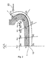
- This is coated with rubber 10 (see FIG. 2), for example of a layer of sealing rubber based on butyl rubber, and a layer of rubber ensuring anchoring the carcass wires on the core during manufacture, then coating them in the vulcanized tire.
- the rubber 10 covering the core 1 makes it possible to retain a wire 4 on the core 1 as it is removed, by a bonding effect.
- the core 1 is driven in rotation by any suitable device, not shown.
- FIG. 1 we see an animation mechanism 3 with single arm resembling what is described in patent application EP 1 231 049.
- a single arm 131 mounted on a plate 130.
- This plate 130 constitutes a support carrying the animation mechanism, here constituted by the arm single 131.
- the plate 130 is slidably mounted on a rail 132.
- the plate 130 comprises a tab 134 to which a connecting rod 138 is articulated.
- the connecting rod 138 is also articulated to a crank 137 rotated by a motor 136.
- the rotational movement of the motor does not not reverse; the operating rate of the device is of course proportional to the motor rotation speed 136.
- the motor 136 can run at constant speed (this is not however compulsory). This is symbolized in the drawing by an arrow F1 pointing on one side only.
- the plate 130 performs an alternative translational movement, guided by the rail 132. The amplitude of this movement depends on the dimension of the crank 137, which can be adjustable (not shown).
- the movement of the arm 131 is controlled by a motor 135 which drives a splined shaft 133.
- the splined shaft 133 crosses the plate 130.
- the rotational movement of the motor 135 is not continuous: the motor 135 is controlled so as to obtain a reciprocating movement of a predetermined amplitude, this movement being transmitted to the arm 131 via a simple internal movement reference to the plate 130 (not shown).
- This type of movement alternative, is symbolized in the drawing by an arrow F2 pointing on both sides. Agree to call this movement command by the expression "electric cam”.
- the movements of the plate 130 and of the arm 131 are synchronous.
- the animation mechanism 3 is similar to what has already been described in the request. EP 1,122,057.
- the depositing member is an eye 6 mounted on an end arm 34.
- a main arm 31 is mounted on a plate 301 by means of a front auxiliary arm 32 and a rear auxiliary arm 33.
- the front auxiliary arm 32 is mounted on a shaft 320 and the arm rear auxiliary 33 is mounted on a shaft 330.
- the end arm 34 inclines relative to the main arm 31 so as to bring the eye 6 closer to the bead of the future tire, even in the case where the manufacturing form is narrower at the height of the bead than at mid flank.
- the plate 301 is slidably mounted on two parallel bars 302.
- the plate 301 comprises a tab 3010 inside which a light 3011 is hollowed out.
- the plate 301 can carry out an alternative translational movement, guided by the bars 302, thanks to a motor 361 controlling a lever 362.
- the rotation of the motor does not reverse, as symbolized in the drawing by an arrow F3 pointing on one side (which does not exclude a variable speed).
- a stud 363 which is engaged in the light 3011.
- the movement of the animation mechanism 3 with multiple arms is controlled by a motor 351 which drives the shaft 320 by means of a telescopic shaft 353.
- the shaft 330 is driven by the shaft 320 via a cascade of gears arranged on the plate 301 and produced so that the shaft 320 can oscillate according to an amplitude for example of approximately 240 °.
- This type of movement is symbolized in the drawing by an arrow F4 pointing on both sides.
- the curve in lines thick interrupted bearing the marks (1), (2) and (3) represents the movement of the eyecup 6
- the curve in center lines carrying the marks a1, a2 and a3 represents the movement in space of axis 310, i.e. also the movement in space of the center of rotation 31R of the arm principal 31
- the curve bearing the marks b1, b2 and b3 represents the movement in nipple space 311.
- the entire 3 arm, single arm or multiple arm animation mechanism is fairly compact. All of the laying members, namely the multi-arm animation mechanism 3, the control of the movement of the plate and the pressing devices 2, including the motor and the drive mechanism, form a subset that can easily be presented to the core appropriately, and can be retracted to present for example to the core other devices used for manufacturing a tire or for evacuating the core to other tire manufacturing stations.
Landscapes
- Engineering & Computer Science (AREA)
- Mechanical Engineering (AREA)
- Tyre Moulding (AREA)
- Tires In General (AREA)
- Ropes Or Cables (AREA)
Applications Claiming Priority (2)
| Application Number | Priority Date | Filing Date | Title |
|---|---|---|---|
| FR0215306 | 2002-12-04 | ||
| FR0215306 | 2002-12-04 |
Publications (3)
| Publication Number | Publication Date |
|---|---|
| EP1426169A2 true EP1426169A2 (de) | 2004-06-09 |
| EP1426169A3 EP1426169A3 (de) | 2004-12-22 |
| EP1426169B1 EP1426169B1 (de) | 2006-09-20 |
Family
ID=32310002
Family Applications (1)
| Application Number | Title | Priority Date | Filing Date |
|---|---|---|---|
| EP03026367A Expired - Lifetime EP1426169B1 (de) | 2002-12-04 | 2003-11-18 | Vorrichtung zur Herstellung eines Verstärkungselements für grossformatige Luftreifen |
Country Status (6)
| Country | Link |
|---|---|
| US (1) | US7128116B2 (de) |
| EP (1) | EP1426169B1 (de) |
| JP (1) | JP2004181962A (de) |
| AT (1) | ATE340070T1 (de) |
| DE (1) | DE60308467T2 (de) |
| ES (1) | ES2268257T3 (de) |
Families Citing this family (5)
| Publication number | Priority date | Publication date | Assignee | Title |
|---|---|---|---|---|
| US20040154727A1 (en) * | 2003-02-11 | 2004-08-12 | Weissert James Thomas | Method and apparatus for manufacturing carcass plies for a tire |
| US7736454B2 (en) | 2004-02-12 | 2010-06-15 | The Goodyear Tire & Rubber Company | Method for incorporating an annular antenna and electronics into a tire |
| FR2909108B1 (fr) * | 2006-11-24 | 2009-07-10 | Michelin Soc Tech | Fil gaine pour la fabrication d'un pneumatique, pneumatique muni de ce fil gaine, dispositif pour la fabrication de ce fil gaine, installation et procede pour la fabrication de ce pneumantique. |
| US20080314524A1 (en) * | 2007-06-20 | 2008-12-25 | Andres Ignacio Delgado | Method for single line tire ply construction |
| US20080314216A1 (en) * | 2007-06-20 | 2008-12-25 | Andres Ignacio Delgado | Tire cord cutting apparatus |
Family Cites Families (7)
| Publication number | Priority date | Publication date | Assignee | Title |
|---|---|---|---|---|
| GB900994A (en) * | 1957-08-05 | 1962-07-11 | Pirelli | Method of tracing the profile of a cam for use on a machine for forming on a collapsible drum annular bands suitable as reinforcements for the casing of vehicle wheel tyres |
| US4830781A (en) * | 1987-09-18 | 1989-05-16 | The Armstrong Rubber Company | Tire body reinforcing component and apparatus and method for producing same |
| FR2804367B1 (fr) * | 2000-02-01 | 2002-09-20 | Sedepro | Appareil a bras oscillant, pour la fabrication d'un renfort de pneumatique a partir d'un seul fil |
| JP4315548B2 (ja) * | 1999-11-19 | 2009-08-19 | 株式会社ブリヂストン | タイヤカーカスの形成装置および形成方法 |
| FR2804368A1 (fr) * | 2000-02-01 | 2001-08-03 | Sedepro | Appareil pour la fabrication de renforts pour pneumatique |
| DE60221580T2 (de) * | 2001-02-07 | 2008-04-17 | Société de Technologie Michelin | Schwingarmvorrichtung zur Herstellung einer Reifenverstärkungsstruktur mit einem einzigen Reifenkord |
| ATE356712T1 (de) * | 2001-02-07 | 2007-04-15 | Michelin Soc Tech | Schwingarmvorrichtung zur herstellung einer reifenverstärkungsstruktur mit einem einzigen reifenkord |
-
2003
- 2003-11-18 ES ES03026367T patent/ES2268257T3/es not_active Expired - Lifetime
- 2003-11-18 DE DE60308467T patent/DE60308467T2/de not_active Expired - Fee Related
- 2003-11-18 EP EP03026367A patent/EP1426169B1/de not_active Expired - Lifetime
- 2003-11-18 AT AT03026367T patent/ATE340070T1/de not_active IP Right Cessation
- 2003-12-01 JP JP2003401412A patent/JP2004181962A/ja not_active Abandoned
- 2003-12-01 US US10/725,761 patent/US7128116B2/en not_active Expired - Fee Related
Also Published As
| Publication number | Publication date |
|---|---|
| EP1426169A3 (de) | 2004-12-22 |
| ATE340070T1 (de) | 2006-10-15 |
| JP2004181962A (ja) | 2004-07-02 |
| US20040108072A1 (en) | 2004-06-10 |
| US7128116B2 (en) | 2006-10-31 |
| ES2268257T3 (es) | 2007-03-16 |
| DE60308467T2 (de) | 2007-09-13 |
| DE60308467D1 (de) | 2006-11-02 |
| EP1426169B1 (de) | 2006-09-20 |
Similar Documents
| Publication | Publication Date | Title |
|---|---|---|
| EP1464472B1 (de) | Schwingarmvorrichtung zur Herstellung einer Reifenverstärkungsstruktur mit einem einzigen Reifenkord | |
| EP0580055B1 (de) | Verfahren und Vorrichtung zum Anordnen eines einfädigen Verstärkungsdrahtes auf einen Kern bei der Herstellung von Reifenkarkassen | |
| EP1537985B1 (de) | Schwingarmvorrichtung zur Herstellung einer Reifenverstärkungsstruktur mit einem einzigen Reifenkord | |
| EP0248301B1 (de) | Verfahren und Vorrichtung zur Herstellung von Verstärkungen für Reifen | |
| EP0582215B1 (de) | Verfahren zum Herstellen von Reifen und Vorrichtung zum Herstellen einer Reifengürtelverstärkung | |
| EP1122055B1 (de) | Gerät mit kombinierten Bewegungen zur Herstellung einer Reifenverstärkung auf der Basis eines Einzeldrahtes | |
| EP1231049A2 (de) | Schwingarmvorrichtung zur Herstellung einer Reifenverstärkungsstruktur mit einem einzigen Reifenkord | |
| EP1517781B1 (de) | Vorrichtung zur herstellung einer verstärkungsstruktur für einen reifen mit einem wulstfahnendrehmechanismus | |
| EP1426170B1 (de) | Vorrichtung mit mehreren Auftragungsarmen zur Herstellung eines Verstärkungselements für Luftreifen | |
| EP1426169B1 (de) | Vorrichtung zur Herstellung eines Verstärkungselements für grossformatige Luftreifen | |
| EP1147864A2 (de) | Schneidevorrichtung mit hoher Geschwindigkeit zum schneiden von Reifenverstärkungselementen | |
| EP1513672B1 (de) | Herstellung einer reifenverstärkungsstruktur mit der volumenregelung der matrix | |
| EP1590169B1 (de) | Eine mit einer drahtführungseinrichtung ausgerüstete vorrichtung zur herstellung von verstärkungselementen für luftreifen und ein herstellungsverfahren unter verwendung einer solchen vorrichtung. | |
| EP1711335B1 (de) | Verfahren und vorrichtung zur herstellung einer reifenverstärkung | |
| EP1279484B1 (de) | Verfahren und Vorrichtung zur Herstellung einer Reifenverstärkungsstruktur | |
| WO2019220061A1 (fr) | Installation et procédé de fabrication de nappes de renfort avec dispositif de retournement a plat de bandelettes | |
| EP1824666B1 (de) | Vorrichtung zur herstellung einer verstärkung für einen luftreifen | |
| WO2014076309A1 (fr) | Machine et procede de decoupe des flancs de pneumatiques en fin de vie | |
| EP0704295A1 (de) | Drahtverstärkung einer Gummimatrix |
Legal Events
| Date | Code | Title | Description |
|---|---|---|---|
| PUAI | Public reference made under article 153(3) epc to a published international application that has entered the european phase |
Free format text: ORIGINAL CODE: 0009012 |
|
| AK | Designated contracting states |
Kind code of ref document: A2 Designated state(s): AT BE BG CH CY CZ DE DK EE ES FI FR GB GR HU IE IT LI LU MC NL PT RO SE SI SK TR |
|
| AX | Request for extension of the european patent |
Extension state: AL LT LV MK |
|
| PUAL | Search report despatched |
Free format text: ORIGINAL CODE: 0009013 |
|
| AK | Designated contracting states |
Kind code of ref document: A3 Designated state(s): AT BE BG CH CY CZ DE DK EE ES FI FR GB GR HU IE IT LI LU MC NL PT RO SE SI SK TR |
|
| AX | Request for extension of the european patent |
Extension state: AL LT LV MK |
|
| 17P | Request for examination filed |
Effective date: 20050622 |
|
| AKX | Designation fees paid |
Designated state(s): AT BE BG CH CY CZ DE DK EE ES FI FR GB GR HU IE IT LI LU MC NL PT RO SE SI SK TR |
|
| GRAP | Despatch of communication of intention to grant a patent |
Free format text: ORIGINAL CODE: EPIDOSNIGR1 |
|
| GRAS | Grant fee paid |
Free format text: ORIGINAL CODE: EPIDOSNIGR3 |
|
| GRAA | (expected) grant |
Free format text: ORIGINAL CODE: 0009210 |
|
| AK | Designated contracting states |
Kind code of ref document: B1 Designated state(s): AT BE BG CH CY CZ DE DK EE ES FI FR GB GR HU IE IT LI LU MC NL PT RO SE SI SK TR |
|
| PG25 | Lapsed in a contracting state [announced via postgrant information from national office to epo] |
Ref country code: IT Free format text: LAPSE BECAUSE OF FAILURE TO SUBMIT A TRANSLATION OF THE DESCRIPTION OR TO PAY THE FEE WITHIN THE PRESCRIBED TIME-LIMIT;WARNING: LAPSES OF ITALIAN PATENTS WITH EFFECTIVE DATE BEFORE 2007 MAY HAVE OCCURRED AT ANY TIME BEFORE 2007. THE CORRECT EFFECTIVE DATE MAY BE DIFFERENT FROM THE ONE RECORDED. Effective date: 20060920 Ref country code: SK Free format text: LAPSE BECAUSE OF FAILURE TO SUBMIT A TRANSLATION OF THE DESCRIPTION OR TO PAY THE FEE WITHIN THE PRESCRIBED TIME-LIMIT Effective date: 20060920 Ref country code: CZ Free format text: LAPSE BECAUSE OF FAILURE TO SUBMIT A TRANSLATION OF THE DESCRIPTION OR TO PAY THE FEE WITHIN THE PRESCRIBED TIME-LIMIT Effective date: 20060920 Ref country code: RO Free format text: LAPSE BECAUSE OF FAILURE TO SUBMIT A TRANSLATION OF THE DESCRIPTION OR TO PAY THE FEE WITHIN THE PRESCRIBED TIME-LIMIT Effective date: 20060920 Ref country code: SI Free format text: LAPSE BECAUSE OF FAILURE TO SUBMIT A TRANSLATION OF THE DESCRIPTION OR TO PAY THE FEE WITHIN THE PRESCRIBED TIME-LIMIT Effective date: 20060920 Ref country code: AT Free format text: LAPSE BECAUSE OF FAILURE TO SUBMIT A TRANSLATION OF THE DESCRIPTION OR TO PAY THE FEE WITHIN THE PRESCRIBED TIME-LIMIT Effective date: 20060920 Ref country code: IE Free format text: LAPSE BECAUSE OF FAILURE TO SUBMIT A TRANSLATION OF THE DESCRIPTION OR TO PAY THE FEE WITHIN THE PRESCRIBED TIME-LIMIT Effective date: 20060920 Ref country code: FI Free format text: LAPSE BECAUSE OF FAILURE TO SUBMIT A TRANSLATION OF THE DESCRIPTION OR TO PAY THE FEE WITHIN THE PRESCRIBED TIME-LIMIT Effective date: 20060920 |
|
| REG | Reference to a national code |
Ref country code: GB Ref legal event code: FG4D Free format text: NOT ENGLISH |
|
| REG | Reference to a national code |
Ref country code: CH Ref legal event code: EP |
|
| REG | Reference to a national code |
Ref country code: IE Ref legal event code: FG4D Free format text: LANGUAGE OF EP DOCUMENT: FRENCH |
|
| REF | Corresponds to: |
Ref document number: 60308467 Country of ref document: DE Date of ref document: 20061102 Kind code of ref document: P |
|
| GBT | Gb: translation of ep patent filed (gb section 77(6)(a)/1977) |
Effective date: 20061101 |
|
| PG25 | Lapsed in a contracting state [announced via postgrant information from national office to epo] |
Ref country code: BE Free format text: LAPSE BECAUSE OF NON-PAYMENT OF DUE FEES Effective date: 20061130 Ref country code: MC Free format text: LAPSE BECAUSE OF NON-PAYMENT OF DUE FEES Effective date: 20061130 |
|
| PG25 | Lapsed in a contracting state [announced via postgrant information from national office to epo] |
Ref country code: SE Free format text: LAPSE BECAUSE OF FAILURE TO SUBMIT A TRANSLATION OF THE DESCRIPTION OR TO PAY THE FEE WITHIN THE PRESCRIBED TIME-LIMIT Effective date: 20061220 Ref country code: DK Free format text: LAPSE BECAUSE OF FAILURE TO SUBMIT A TRANSLATION OF THE DESCRIPTION OR TO PAY THE FEE WITHIN THE PRESCRIBED TIME-LIMIT Effective date: 20061220 Ref country code: BG Free format text: LAPSE BECAUSE OF FAILURE TO SUBMIT A TRANSLATION OF THE DESCRIPTION OR TO PAY THE FEE WITHIN THE PRESCRIBED TIME-LIMIT Effective date: 20061220 |
|
| PG25 | Lapsed in a contracting state [announced via postgrant information from national office to epo] |
Ref country code: PT Free format text: LAPSE BECAUSE OF FAILURE TO SUBMIT A TRANSLATION OF THE DESCRIPTION OR TO PAY THE FEE WITHIN THE PRESCRIBED TIME-LIMIT Effective date: 20070312 |
|
| REG | Reference to a national code |
Ref country code: ES Ref legal event code: FG2A Ref document number: 2268257 Country of ref document: ES Kind code of ref document: T3 |
|
| REG | Reference to a national code |
Ref country code: IE Ref legal event code: FD4D |
|
| PLBE | No opposition filed within time limit |
Free format text: ORIGINAL CODE: 0009261 |
|
| STAA | Information on the status of an ep patent application or granted ep patent |
Free format text: STATUS: NO OPPOSITION FILED WITHIN TIME LIMIT |
|
| 26N | No opposition filed |
Effective date: 20070621 |
|
| BERE | Be: lapsed |
Owner name: MICHELIN RECHERCHE ET TECHNIQUE S.A. Effective date: 20061130 Owner name: SOC. DE TECHNOLOGIE MICHELIN Effective date: 20061130 |
|
| PG25 | Lapsed in a contracting state [announced via postgrant information from national office to epo] |
Ref country code: GR Free format text: LAPSE BECAUSE OF FAILURE TO SUBMIT A TRANSLATION OF THE DESCRIPTION OR TO PAY THE FEE WITHIN THE PRESCRIBED TIME-LIMIT Effective date: 20061221 |
|
| PG25 | Lapsed in a contracting state [announced via postgrant information from national office to epo] |
Ref country code: EE Free format text: LAPSE BECAUSE OF FAILURE TO SUBMIT A TRANSLATION OF THE DESCRIPTION OR TO PAY THE FEE WITHIN THE PRESCRIBED TIME-LIMIT Effective date: 20060920 |
|
| PG25 | Lapsed in a contracting state [announced via postgrant information from national office to epo] |
Ref country code: CH Free format text: LAPSE BECAUSE OF NON-PAYMENT OF DUE FEES Effective date: 20071130 Ref country code: LI Free format text: LAPSE BECAUSE OF NON-PAYMENT OF DUE FEES Effective date: 20071130 Ref country code: HU Free format text: LAPSE BECAUSE OF FAILURE TO SUBMIT A TRANSLATION OF THE DESCRIPTION OR TO PAY THE FEE WITHIN THE PRESCRIBED TIME-LIMIT Effective date: 20070321 Ref country code: TR Free format text: LAPSE BECAUSE OF FAILURE TO SUBMIT A TRANSLATION OF THE DESCRIPTION OR TO PAY THE FEE WITHIN THE PRESCRIBED TIME-LIMIT Effective date: 20060920 |
|
| REG | Reference to a national code |
Ref country code: CH Ref legal event code: PL |
|
| PG25 | Lapsed in a contracting state [announced via postgrant information from national office to epo] |
Ref country code: CY Free format text: LAPSE BECAUSE OF FAILURE TO SUBMIT A TRANSLATION OF THE DESCRIPTION OR TO PAY THE FEE WITHIN THE PRESCRIBED TIME-LIMIT Effective date: 20060920 |
|
| PGFP | Annual fee paid to national office [announced via postgrant information from national office to epo] |
Ref country code: DE Payment date: 20081121 Year of fee payment: 6 Ref country code: LU Payment date: 20081127 Year of fee payment: 6 Ref country code: NL Payment date: 20081113 Year of fee payment: 6 |
|
| PGFP | Annual fee paid to national office [announced via postgrant information from national office to epo] |
Ref country code: ES Payment date: 20081121 Year of fee payment: 6 |
|
| PGFP | Annual fee paid to national office [announced via postgrant information from national office to epo] |
Ref country code: IT Payment date: 20081120 Year of fee payment: 6 |
|
| PGFP | Annual fee paid to national office [announced via postgrant information from national office to epo] |
Ref country code: FR Payment date: 20081113 Year of fee payment: 6 |
|
| PGFP | Annual fee paid to national office [announced via postgrant information from national office to epo] |
Ref country code: GB Payment date: 20081117 Year of fee payment: 6 |
|
| REG | Reference to a national code |
Ref country code: NL Ref legal event code: V1 Effective date: 20100601 |
|
| GBPC | Gb: european patent ceased through non-payment of renewal fee |
Effective date: 20091118 |
|
| REG | Reference to a national code |
Ref country code: FR Ref legal event code: ST Effective date: 20100730 |
|
| PG25 | Lapsed in a contracting state [announced via postgrant information from national office to epo] |
Ref country code: NL Free format text: LAPSE BECAUSE OF NON-PAYMENT OF DUE FEES Effective date: 20100601 Ref country code: FR Free format text: LAPSE BECAUSE OF NON-PAYMENT OF DUE FEES Effective date: 20091130 |
|
| PG25 | Lapsed in a contracting state [announced via postgrant information from national office to epo] |
Ref country code: DE Free format text: LAPSE BECAUSE OF NON-PAYMENT OF DUE FEES Effective date: 20100601 |
|
| PG25 | Lapsed in a contracting state [announced via postgrant information from national office to epo] |
Ref country code: GB Free format text: LAPSE BECAUSE OF NON-PAYMENT OF DUE FEES Effective date: 20091118 |
|
| REG | Reference to a national code |
Ref country code: ES Ref legal event code: FD2A Effective date: 20110325 |
|
| PG25 | Lapsed in a contracting state [announced via postgrant information from national office to epo] |
Ref country code: IT Free format text: LAPSE BECAUSE OF NON-PAYMENT OF DUE FEES Effective date: 20091118 |
|
| PG25 | Lapsed in a contracting state [announced via postgrant information from national office to epo] |
Ref country code: LU Free format text: LAPSE BECAUSE OF NON-PAYMENT OF DUE FEES Effective date: 20091118 |
|
| PG25 | Lapsed in a contracting state [announced via postgrant information from national office to epo] |
Ref country code: ES Free format text: LAPSE BECAUSE OF NON-PAYMENT OF DUE FEES Effective date: 20110314 |
|
| PG25 | Lapsed in a contracting state [announced via postgrant information from national office to epo] |
Ref country code: ES Free format text: LAPSE BECAUSE OF NON-PAYMENT OF DUE FEES Effective date: 20091119 |