EP1426228A2 - Dispositif d'assistance à la conduite d'un véhicule - Google Patents
Dispositif d'assistance à la conduite d'un véhicule Download PDFInfo
- Publication number
- EP1426228A2 EP1426228A2 EP03023252A EP03023252A EP1426228A2 EP 1426228 A2 EP1426228 A2 EP 1426228A2 EP 03023252 A EP03023252 A EP 03023252A EP 03023252 A EP03023252 A EP 03023252A EP 1426228 A2 EP1426228 A2 EP 1426228A2
- Authority
- EP
- European Patent Office
- Prior art keywords
- accelerator pedal
- reaction force
- vehicle
- operating speed
- correction amount
- Prior art date
- Legal status (The legal status is an assumption and is not a legal conclusion. Google has not performed a legal analysis and makes no representation as to the accuracy of the status listed.)
- Granted
Links
Images


Classifications
-
- B—PERFORMING OPERATIONS; TRANSPORTING
- B60—VEHICLES IN GENERAL
- B60W—CONJOINT CONTROL OF VEHICLE SUB-UNITS OF DIFFERENT TYPE OR DIFFERENT FUNCTION; CONTROL SYSTEMS SPECIALLY ADAPTED FOR HYBRID VEHICLES; ROAD VEHICLE DRIVE CONTROL SYSTEMS FOR PURPOSES NOT RELATED TO THE CONTROL OF A PARTICULAR SUB-UNIT
- B60W50/00—Details of control systems for road vehicle drive control not related to the control of a particular sub-unit, e.g. process diagnostic or vehicle driver interfaces
- B60W50/08—Interaction between the driver and the control system
- B60W50/14—Means for informing the driver, warning the driver or prompting a driver intervention
- B60W50/16—Tactile feedback to the driver, e.g. vibration or force feedback to the driver on the steering wheel or the accelerator pedal
-
- B—PERFORMING OPERATIONS; TRANSPORTING
- B60—VEHICLES IN GENERAL
- B60K—ARRANGEMENT OR MOUNTING OF PROPULSION UNITS OR OF TRANSMISSIONS IN VEHICLES; ARRANGEMENT OR MOUNTING OF PLURAL DIVERSE PRIME-MOVERS IN VEHICLES; AUXILIARY DRIVES FOR VEHICLES; INSTRUMENTATION OR DASHBOARDS FOR VEHICLES; ARRANGEMENTS IN CONNECTION WITH COOLING, AIR INTAKE, GAS EXHAUST OR FUEL SUPPLY OF PROPULSION UNITS IN VEHICLES
- B60K26/00—Arrangement or mounting of propulsion-unit control devices in vehicles
- B60K26/02—Arrangement or mounting of propulsion-unit control devices in vehicles of initiating means or elements
- B60K26/021—Arrangement or mounting of propulsion-unit control devices in vehicles of initiating means or elements with means for providing feel, e.g. by changing pedal force characteristics
Definitions
- the present invention relates to technology for assisting driver's operations, more particularly, to a driving assist system for a vehicle that assists operations by a driver.
- the driver's perception of the accelerator pedal reaction force depends on his condition. In other words, it is difficult to warn the driver in a manner appropriate to his perception by controlling the accelerator pedal reaction force based on the distance between the subject vehicle and the preceding vehicle.
- the present invention is to provide a driving assist system for a vehicle capable of conveying a risk potential in a manner appropriate to the state of the driver' s perception.
- a driving assist system for a vehicle comprises: a driving state recognition means (10, 20) for detecting a vehicle condition and a traveling environment of a subject vehicle; a risk potential calculation means (30) for calculating risk potential around the subject vehicle based on signals from the driving state recognition means (10, 20); a reaction force control means (30, 60) for controlling operation reaction force to be generated in a vehicle operating unit, based on the risk potential calculated by the risk potential calculation means (30); an operating state detection means (30, 80) for detecting operating state of the vehicle operating unit by a driver; and a reaction force correction means (30) for correcting the'operation reaction force of the vehicle operating unit controlled by the reaction force control means (30, 60), based on signals from the operating state detection means (30, 80).
- a vehicle driving assist method detects a vehicle condition and a traveling environment of a subject vehicle; calculates risk potential around the subject vehicle based on the vehicle condition and the traveling environment having been detected; detects operating state of a vehicle operating unit by a driver; and controls operation reaction force to be generated in the vehicle operating unit, based on the risk potential and the operating state of the vehicle operating unit.
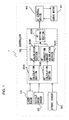
- FIG. 1 is a block diagram showing the structure of a driving assist system for a vehicle according to an embodiment of the present invention.
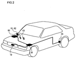
- FIG. 2 is a structural diagram of a vehicle fitted with the vehicle driving assist system shown in FIG. 1.
- FIG. 3 is a structural diagram of an accelerator pedal and the vicinity thereof.
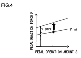
- FIG. 4 is a figure showing a relationship between an accelerator pedal operation amount and an accelerator pedal reaction force.
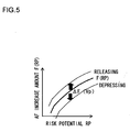
- FIG. 5 illustrates the concept of reaction force correction in a first embodiment.
- FIG. 6 is a flow chart showing the procedural flow of accelerator pedal reaction force control program executed in the first embodiment.
- FIG. 7 is a figure showing a relationship between an accelerator pedal operation speed and a reaction force correction amount.
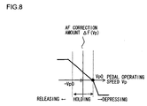
- FIG. 8 is a figure showing a relationship between an accelerator pedal operation speed and a reaction force correction amount.
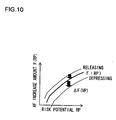
- FIG. 10 illustrates the concept of reaction force correction in a second embodiment.
- FIG. 11 is a figure showing a relationship between an accelerator pedal operation speed and a reaction force correction amount.
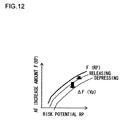
- FIG. 12 illustrates the concept of reaction force correction in a third embodiment.
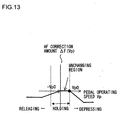
- FIG. 13 is a figure showing a relationship between an accelerator pedal operation speed and a reaction force correction amount.
- FIG. 1 shows the structure of a vehicle driving assist system 1 of the first embodiment
- FIG. 2 is a structural diagram of a vehicle f itted with the vehicle driving assist system 1.
- FIG. 3 is a structural diagramof an accelerator pedal and the vicinity thereof.
- a laser radar 10 is attached to a front grill of the vehicle or to a bumper etc., and propagates infrared pulses in a forward horizontal direction for scanning.
- the laser radar 10 measures reflected radiation of infrared pulses reflected by a plurality of reflecting objects ahead, such as the rear of a vehicle in front, and detects distance (vehicle distance) from the subject vehicle to a preceding vehicle and relative velocity (relative speed) of vehicles based on the elapsed time the reflected radiation to be received.
- the laser radar 10 outputs the detected vehicle distance and relative speed between vehicles to a controller 30.
- the laser radar 10 can scan the forward region which is about 6 degrees each side of an axis parallel to the vehicle longitudinal centerline, and objects existing within this range are detected.
- a vehicle speed sensor 20 detects traveling speed of the subject vehicle from rotational speed of a wheel thereof or rotational speed of an output shaft of a transmission, and outputs the vehicle speed to the controller 30.
- a servo motor 61 and an accelerator pedal stroke sensor 62 are connected to an accelerator pedal 63 via a link mechanism.
- the accelerator pedal stroke sensor 62 detects an operation amount of the accelerator pedal 63 converted to a rotation angle of the servo motor 61 through the link mechanism.
- the accelerator pedal stroke sensor 63 outputs the detected amount to the controller 30.
- the controller 30 performs overall control of the vehicle driving assist system 1.
- the controller 30 detects, obstacle situation around the subject vehicle based on signals input from the laser radar 10 and the vehicle speed sensor 20, and calculates risk potential of the subject vehicle with respect to the preceding vehicle based on the detected obstacle situation.
- the controller 30 then performs the accelerator pedal reaction force control according to the risk potential thus calculated as will be described later.
- An accelerator pedal reaction force control device (AF control device) 60 controls the servo motor 61 built into the linkmechanism of the accelerator pedal 63 according to a signal from the controller 30.
- the servo motor 61 controls torque and rotation angle thereof in response to commands from the AF control device 60 so as to control reaction force generated when the driver operates the accelerator pedal 63.
- FIG. 4 shows a relationship between the accelerator pedal operation amount S and the accelerator pedal reaction force F.
- the accelerator pedal reaction force F may increase linearly along with increase of the operation amount S of the accelerator pedal 63 as shown in FIG. 4.
- the function Fini of the accelerator pedal reaction force F with respect to the accelerator pedal operation amount S when the accelerator pedal reaction force control is not being carried out is taken as being a normal reaction force characteristic.
- the normal reaction force characteristic Fini may be obtained, for example, by spring force of a torsion spring (not shown in the drawings) provided at the center of rotation of the servo motor 61.
- the controller 30 comprises a CPU and CPU peripheral devices, such as ROM, RAM etc.
- the controller 30 constitutes a risk potential calculation section (RP calculation section) 30A, a reaction force calculation section (AF calculation section) 30B, an accelerator pedal operation speed calculation section (AS calculation section) 30C, a reaction force correction amount calculation section (AF correction amount calculation section) 30D, and a reaction force setting section (AF setting section) 30E in the form of software in CPU.
- RP calculation section a risk potential calculation section
- AF calculation section reaction force calculation section
- AS calculation section accelerator pedal operation speed calculation section
- AF correction amount calculation section reaction force correction amount calculation section
- AF setting section reaction force setting section
- the RP calculation section 30A calculates the risk potential RP according to traveling state of the subject vehicle and the surrounding environment based on signals input from the laser radar 10 and the vehicle speed sensor 20.
- the risk potential RP calculated in the RP calculation section 30A is output to the AF calculation section 30B.
- the AS calculation section 30C calculates operating speed Vp of the accelerator pedal 63 by using the accelerator pedal operation amount S input from the stroke sensor 62. For instance, the operating speed Vp may be calculated from changes in the accelerator pedal operation amount S along time stored in a memory of the controller 30.
- the AF correction amount calculation section 30D calculates a reaction force correction amount (AF correction amount) ⁇ F(Vp) for correcting the accelerator pedal reaction force based on the operating speed Vp calculated in the AS calculation section 30C.
- the AF setting section 30E calculates a reaction force control amount (AF control amount) ⁇ F to output to the AF control device 60 using the AF increase amount F(RP) calculated in the AF calculation section 30B and the AF correction amount ⁇ F(Vp) calculated in the AF correction amount calculation section 30D.
- the accelerator pedal reaction force F is corrected by taking into account of the pushing-back force from the accelerator pedal 63 that the driver perceives so that the risk potential RP in the vehicle surroundings is conveyed to the driver accurately regardless of operating state of the driver.
- driver's operating state is determined using the operating speed Vp of the accelerator pedal 63.
- FIG. 5 schematically illustrates the relationship among the risk potential RP, the AF increase amount F(RP), and the AF correction amount ⁇ F(Vp).
- the AF increase amount F(RP) increases as the risk potential RP becomes greater.
- the AF increase amount F(RP) is adjusted by setting the AF correction amount ⁇ F(Vp) to decrease the accelerator pedal reaction force F.
- the AF increase amount F(RP) is set so that the accelerator pedal reaction force F becomes smaller as the depressing speed Vp of the accelerator pedal 63 increases.
- the AF increase amount F(RP) is adjusted by setting the AF correction amount ⁇ F(Vp) to increase the accelerator pedal reaction force F.
- the AF increase amount F(RP) is set so that the accelerator pedal reaction force F becomes greater as the releasing speed Vp of the accelerator pedal 63 increases.
- FIG. 6 is a flow chart showing the procedural flow of a drive operation assist control program executed in the controller 30. These processing procedures are executed in the controller 30 continuously at predetermined time intervals of, e. g. , 50msec.
- step S101 the AF correction amount ⁇ F(Vp) is set to 0 as an initial value.
- step S102 driving conditions in the vehicle surroundings, such as traveling state of the subject vehicle and obstacle condition around the subject vehicle are read.
- a distance D between the subject vehicle and an obstacle, for instance a preceding vehicle in front of the subject vehicle, and a relative speed Vr between the subject vehicle and the preceding vehicle detected by the laser radar 10 are read.
- a subject vehicle speeds Vf detected by the vehicle speed sensor 20 is read.
- step S103 the risk potential RP in the vehicle surroundings is calculated based on data of the driving conditions read in step S102.
- time to contact (TTC) and time headway (THW) with respect to the obstacle having been recognized are calculated in order to calculate the risk potential RP.
- TTC is a physical quantity representing current degree of proximity of the subject vehicle to the preceding vehicle.
- TTC indicates how many seconds later the vehicle distance D will become zero and the subject vehicle and the preceding vehicle come into contact with each other.
- THW is a physical quantity representing a predicted extent of influence on TTC due to future change in the preceding vehicle speed while the subject vehicle is following the preceding vehicle.
- THW represents the extent of influence upon TTC when it is assumed that the relative velocity Vr will change.
- THW is obtained by dividing the vehicle distance D by the subject vehicle speed Vf, and represents a period of time until the subject vehicle reaches the current position of the preceding vehicle. If THW is large, there is not a lot of influence on the degree of proximity to preceding vehicle even if the preceding vehicle velocity changes in the future. It should be understood that, if the subject vehicle follows the preceding vehicle at the subject vehicle speed Vf equal to the preceding vehicle speed Va, it is also possible to calculate THW by substituting the preceding vehicle speed Va for the subject vehicle speed Vf in expression 2.
- the AF increase amount F (RP) is calculated based on the risk potential RP calculated in step S103.
- the AF increase amount F(RP) increases as the risk potential RP becomes greater as shown in FIG. 5.
- the AF increase amount F (RP) may be set to be proportional to the risk potential RP with the following expression 4.
- F(RP) k x RP
- k is a constant set appropriately.
- step S105 change rate dRP/dt of the risk potential RP calculated in step S103 is calculated.
- the change rate dRP/dt may be obtained by differentiating the risk potential RP with respect to time t.
- step S106 it is decided as to whether or not the change rate dRP/dt of the risk potential RP calculated in step S105 is a positive value, in other words, whether the risk potential RP is increasing or decreasing. If an affirmative decision is made in step S106 so that the risk potential RP is increasing, the flow of control proceeds to step S107.
- step S107 the accelerator pedal operation amount S detected by the accelerator pedal stroke sensor 62 is read.
- step S108 the operating speed Vp of the accelerator pedal 63 is calculated.
- step S109 the AF correction amount ⁇ F(Vp) is calculated based on the operating speed Vp of the accelerator pedal 63 calculated in step S108.
- a relationship between the accelerator pedal operating speed Vp and the AF correction amount ⁇ F(Vp) is shown in FIG. 7.
- a vertical axis of FIG. 7 represents the AF correction amount ⁇ F(Vp), and a horizontal axis represents the accelerator pedal operating speed Vp.
- the AF correction amount ⁇ F(Vp) is set so that the accelerator pedal reaction force F becomes smaller as the depressing speed Vp of the accelerator pedal 63 becomes larger.
- the AF correction amount ⁇ F(Vp) shows a negative value, and the absolute value of the amount ⁇ F(Vp) becomes larger as the operating speed Vp becomes faster.
- the AF correction amount ⁇ F(Vp) is set so that the accelerator pedal reaction force F becomes larger as a value of the operating speed Vp becomes smaller.
- the AF correction amount ⁇ F(Vp) becomes larger as the releasing speed Vp of the accelerator pedal 63 becomes higher.
- the AF correction amount ⁇ F(Vp) is indicated by a positive value.
- step S106 If, on the other hand, a negative decision is made in step S106, the flow of control proceeds to step S112.
- step S112 the AF correction amount ⁇ F(Vp) is set to 0 so as not to carry out adjustment to the accelerator pedal reaction force F when the risk potential RP decreases.
- the flow of control proceeds step S110.
- step S110 the AF control amount ⁇ F is calculated by using the AF increase amount F(RP) according to the risk potential RP calculated in step S104 and the AF correction amount ⁇ F(Vp) according to the operating speed Vp of the accelerator pedal 63 calculated in step S109 or S112.
- the AF control amount ⁇ F is calculated by adding the AF correction amount ⁇ F(Vp) to the AF increase amount F(RP) as shown in expression 5.
- step S111 the AF control mount ⁇ F calculated in step S110 is output to the AF control device 60.
- the AF control device 60 controls the servo motor 61 so as to generate the operation reaction force in the accelerator pedal 63, which is obtained by adding the AF control amount ⁇ F input from the controller 30 to the normal reaction force characteristic Fini. The processing for this time then terminates.
- step S109 of FIG. 6 the AF correction amount ⁇ F(Vp) was calculated using a map of FIG. 7 so that the driver can perceive the same reaction force F from the accelerator pedal when the risk potential RP is the same, regardless of the operating state of the accelerator pedal 63. Maps other than the map shown in FIG. 7 can be used if appropriate AF correction amount ⁇ F(Vp) can be calculated.
- FIG. 8 shows another example of a map of the AF correction amount ⁇ F(Vp) with respect to the accelerator pedal operating speed Vp.
- the map shown in FIG. 8 is set so that a slope of the AF correction amount ⁇ F(Vp) when the accelerator pedal 63 is being depressed (Vp > Vp0) is different from a slope of the AF correction amount ⁇ F(Vp) when the accelerator pedal 63 is held or being released (Vp ⁇ Vp0). More specifically, the slope of the AF correction amount ⁇ F(Vp) when depressing the accelerator pedal 63 is set to become larger than the slope of the AF correction amount ⁇ F(Vp) when holding or releasing the pedal.
- the slope of the AF correction amount ⁇ F(Vp) is set to become larger than when the pedal is being held or released.
- extent of the accelerator pedal reaction force correction when depressing the accelerator pedal 63 is set larger than extent of the correction when holding or releasing the pedal, and moreover, the accelerator pedal reaction force F is adjusted to become smaller as the pedal depressing speed Vp increases.
- the driver is sensitive to the pushing-back force from the accelerator pedal 63 when depressing the accelerator pedal 63 intently as explained above.
- the accelerator pedal reaction force F is adjusted to be smaller so as not to generate the reaction force F larger than necessary. In this way, the risk potential RP in the vehicle surroundings can be conveyed to the driver while maintaining operativeness of the accelerator pedal 63 when the driver is pressing down the pedal intently.
- the slope of the AF correction amount ⁇ F(Vp) is set to be constant in a region where the accelerator pedal operating speed Vp is equal to or smaller than the predetermined value Vp0. In this way, as the operating speed Vp of releasing the accelerator pedal 63 becomes higher, the accelerator pedal reaction force F is adjusted to be greater. Thus, the risk potential RP in the vehicle surroundings can be reliably conveyed to the driver even in situation where the driver is not sensitive to the pushing-back force from the accelerator pedal 63.
- FIG. 9 shows another example of a map of the AF correction amount ⁇ F(Vp) with respect to the accelerator pedal operating speed Vp.
- the map of FIG. 9 includes an unchanging region where the AF correction amount ⁇ F(Vp) does not vary even if the operating speed Vp changes, within a region where the accelerator pedal operating speed Vp is small. More particularly, as shown in FIG. 9, a range of the accelerator pedal operating speed Vp from 0 to the predetermined value Vp0 (0 ⁇ Vp ⁇ Vp0) is taken as the unchanging region. Inaddition, a slope of the AF correction amount ⁇ F(Vp) when depressing the accelerator pedal 63 (Vp > Vp0) is set to be larger than a slope of the amount ⁇ F(Vp) when holding or releasing the accelerator pedal 63.
- the unchanging region is included in the map of the AF correction amount ⁇ F(Vp)
- theacceleratorpedalreaction force F does not vary needlessly in response to slight change in the pedal operating speed Vp when holding the accelerator pedal 63 at small operating speed Vp. In this way, the reaction force control system can be stabilized.
- the slope of the AF correction amount ⁇ F(Vp) when the accelerator pedal 63 is being depressed is set to be larger.
- an absolute value of the AF correction amount ⁇ F(Vp) becomes greater to reduce the AF control amount ⁇ F.
- the risk potential RP in the vehicle surroundings can be conveyed to the driver while maintaining operativeness of the pedal when the driver is depressing the accelerator pedal 63 intently.
- the structure of the vehicle driving assist system of the second embodiment is identical to that of the first embodiment, and thus, its explanation is omitted. Here, explanation will focus on points that differentiate the second embodiment from the first embodiment.
- step S109 in the flow chart of FIG. 6 differs from the first embodiment described above.
- the accelerator pedal reaction force F was corrected, taking account of the pushing-back force that the driver perceives when operating the accelerator pedal 63.
- the accelerator pedal reaction force F will be corrected, taking account of driver's sensitivity to the accelerator pedal reaction force F when operating the accelerator pedal 63.
- the driver When operating the accelerator pedal 63, the driver feels the operation reaction force of the accelerator pedal 63 as a pushing-back force acting to release the pedal.
- the driver becomes more sensitive to the pushing-back force as he operates the accelerator pedal 63 more intently. That is, when the driver operates the accelerator pedal 63 quickly with intention, driver's sense sharpens and he can recognize the accelerator pedal reaction force F easily, whether he is depressing or releasing the accelerator pedal 63.
- the driver when the driver does not operate the accelerator pedal 63 intently or operates it aimlessly, the driver tends to become insensitive to the accelerator pedal reaction force F. Especially, if the risk potential RP increases and the accelerator pedal reaction force F increases gradually while the driver is holding the accelerator pedal 63, the accelerator pedal 63 may move slowly back to its neutral position along with increase in the reaction force F. In this case, the driver may not recognize increase in the accelerator pedal reaction force F.
- the accelerator pedal reaction force F is corrected, taking account of driver's sensitivity to the accelerator pedal reaction force F, in order to precisely notify the risk potential RP in the vehicle surroundings to the driver regardless of the operating state of the driver.
- FIG. 10 schematically illustrates the relationship among the risk potential RP, the AF increase amount F(RP), and the AF correction amount ⁇ F(Vp).
- the AF increase amount F(RP) increases as the risk potential RP becomes greater.
- the AF increase amount F(RP) is adjusted by setting the AF correction amount ⁇ F(Vp) appropriately so that the accelerator pedal reaction force F decreases as the depressing speed Vp becomes higher.
- the AF increase amount F(RP) is adjusted by setting the AF correction amount ⁇ F(Vp) so that the accelerator pedal reaction force Fbecomes greater as the releasing speed Vp becomes slower.
- the AF increase amount F(RP) is adjusted so that the accelerator pedal reaction force F becomes relatively small as the accelerator pedal 63 is being released quickly.
- a range of the accelerator pedal operating speed Vp from 0 to the predetermined value Vp0 (0 ⁇ Vp ⁇ Vp0) is set as an unchanging region where the AF correction amount ⁇ F(Vp) does not vary even if the operating speed Vp changes.
- the AF correction amount ⁇ F(Vp) becomes larger as the operating speed Vp approaches to 0 or becomes slower. That is, when the accelerator pedal 63 is held or being released at the operating speed Vp ⁇ 0, the AF correction amount ⁇ F (Vp) is set to become greater as the accelerator pedal 63 is operated slowly and the absolute value of the operating speed Vp becomes smaller.
- the AF control amount ⁇ F to be actually output to the AF control device 60 is calculated by adding the AF correction amount ⁇ F(Vp) calculated according to the map of FIG. 11 to the AF increase amount F(RP) calculated according to the risk potential RP as represented in expression 5.
- the accelerator pedal reaction force F is adj usted, taking driver's sensitivity to the accelerator pedal reaction force F into consideration. More particularly, when depressing the accelerator pedal 63, the accelerator pedal reaction force F is corrected to become smaller as the operating speed Vp becomes higher. On the other hand, when releasing the accelerator pedal 63 (Vp ⁇ 0), the accelerator pedal reaction force F is corrected to become larger as the operating speed Vp becomes slower. In this way, the risk potential RP in the vehicle surroundings can be reliably conveyed to the driver by increasing the accelerator pedal reaction force F when the driver operates the accelerator pedal 63 slowly and is insensitive to the reaction force. For instance, even when the accelerator pedal 63 is gradually moved back to its neutral position in response to increase in the accelerator pedal reaction force F, it is possible to reliably convey the risk potential RP to the driver by increasing the accelerator pedal reaction force F further more.
- the accelerator pedal reaction force F is set to become smaller so that the risk potential RP can be conveyed to the driver without disturbing driver's operation of the accelerator pedal 63.
- a region where the depressing speed Vp of the accelerator pedal 63 is small and less than the predetermined value Vp0 is set as the unchanging region of the AF correction force ⁇ F(Vp).
- the accelerator pedal reaction force F does not change in response to slight change in the operating speed Vp while the driver is holding the accelerator pedal 63. Accordingly, the reaction force control system can be stabilized.
- the AF correction amount ⁇ F(Vp) is calculated, taking account of driver's sensitivity to the accelerator pedal reaction force F.
- FIG. 12 schematically illustrates the relationship among the risk potential RP, the AF increase amount F(RP), and the AF correction amount ⁇ F(Vp).
- the AF increase amount F(RP) increases as the risk potential RP becomes greater.
- the AF increase amount F(RP) is adjusted by setting the AF correction amount ⁇ F(Vp) so that the accelerator pedal reaction force F becomes smaller as the operating speed Vp becomes higher, whether the accelerator pedal 63 is being depressed or released.
- extent of adjustment to the AF increase amount F(RP) with respect to the operating speed Vp is greater compared to when the accelerator pedal 63 is being released.
- the accelerator pedal reaction force F is adjusted to become smaller as the depressing speed Vp of the accelerator pedal 63 becomes higher.
- FIG. 13 shows an example of a map of the AF correction amount ⁇ F(Vp) with respect to the accelerator pedal operating speed Vp.
- the AF correction amount ⁇ F(Vp) is set so that the accelerator pedal reaction force F becomes smaller as the depressing speed Vp of the accelerator pedal 63 becomes higher.
- the AF correction amount ⁇ F(Vp) is indicated by a negative value, and the absolute value of the amount ⁇ F(Vp) becomes larger as the operating speed Vp becomes faster.
- a range of the accelerator pedal operating speed Vp from 0 to the predetermined value Vp0 (0 ⁇ Vp ⁇ Vp0) is set as an unchanging region where the AF correction amount ⁇ F(Vp) does not vary even if the operating speed Vp changes.
- the AF correction amount ⁇ F(Vp) is set to reduce the accelerator pedal reaction force F as the operating speed Vp lowers.
- the operating speed Vp and the AF correction amount ⁇ F(Vp) are indicated by negative values, and the absolute value of the amount ⁇ F(VP) increases as the releasing speed Vp of the accelerator pedal 63 becomes higher.
- the AF control amount ⁇ F to be actually output to the AF control device 60 is calculated by adding the AF correction amount ⁇ F(Vp) calculated according to the map of FIG. 13 to the AF increase amount F(RP) calculated according to the risk potential RP as represented in expression 5.
- the accelerator pedal reaction force F has been adjusted, taking account of the driver's sensitivity to the accelerator pedal reaction force F. More particularly, the accelerator pedal reaction force F is corrected to become smaller as the operating speed Vp becomes higher when the accelerator pedal 63 is being depressed, as shown in FIG. 13. When the accelerator pedal 63 is being released, the accelerator pedal reaction force F is also corrected to become smaller as the operating speed Vp becomes higher. That is, when the driver operates the accelerator pedal 63 intently and quickly and is sensitive to the reaction force, the accelerator pedal reaction force F is made to be smaller. In this way, the risk potential RP can surely be conveyed to the driver without disturbing driver's operation of the accelerator pedal 63.
- the accelerator pedal reaction force F does not vary in response to slight change in the operating speed Vp while the accelerator pedal 63 is being held. In this way, the reaction force control system can be stabilized.
- a slope of the AF correction amount ⁇ F(Vp) in case of depressing the accelerator pedal 63 is set larger than a slope of the amount ⁇ F(Vp) in case of releasing the accelerator pedal 63.
- the absolute value of the AF correction amount ⁇ F(Vp) increases furthermore to reduce the AF control amount ⁇ F. Accordingly, the risk potential RP in the vehicle surroundings can be notified to the driver while maintaining operativeness of the pedal when the driver is depressing the accelerator pedal 63 intently.
- the AF increase amount F (RP) increases linearly with respect to increase in the risk potential RP. It would also be possible to set the AF increase amount F(RP) to increase according to an exponential function with respect to the risk potential RP.
- the risk potential RP in the vehicle surroundings was calculated using TTC and THW, but the present invention is not to be limited by this feature.
- the AF correction amount ⁇ F(Vp) was set to be 0 when the risk potential RP was decreasing, but the present invention is not to be limited by this feature. For instance, when the risk potential RP is decreasing, it would be also possible to gradually reduce the AF correction amount ⁇ F(Vp).
- the AF correction amount ⁇ F(Vp) was set to vary linearly with respect to the accelerator pedal operating speed VP, but the present invention is not to be considered as being limited by this feature. That is, as long as the accelerator pedal reaction force F is appropriately adjusted according to the operating speed Vp and a direction of its operation, the AF correction amount map can be modified. Moreover, if the accelerator pedal reaction force F can be appropriately adjusted according to the operating state of the accelerator pedal 63, the risk potential RP can be corrected according to the operating speed Vp and a direction of its operation. That is, it is possible to correct either the AF control amount ⁇ F or the risk potential RP to appropriately adjust the accelerator pedal reaction force F. In addition, it would be also possible to correct both of the AF control amount ⁇ F and the risk potential RP.
- the correcting methods of the accelerator pedal reaction force F as described in the first through third embodiments may be applied to operation reaction force control of a brake pedal.
- the vehicle condition and driving environment of the vehicle surroundings was detected by using the laser radar 10 and the vehicle speed sensor 20.
- the present invention is not thus limited, and it is also possible to use, for example, other type of detectors instead of the laser radar 10 such as milliwave radar, a CCD camera or a CMOS camera to detect the vehicle condition and driving environment.
Landscapes
- Engineering & Computer Science (AREA)
- Automation & Control Theory (AREA)
- Human Computer Interaction (AREA)
- Transportation (AREA)
- Mechanical Engineering (AREA)
- Auxiliary Drives, Propulsion Controls, And Safety Devices (AREA)
- Control Of Driving Devices And Active Controlling Of Vehicle (AREA)
- Control Of Throttle Valves Provided In The Intake System Or In The Exhaust System (AREA)
Applications Claiming Priority (2)
| Application Number | Priority Date | Filing Date | Title |
|---|---|---|---|
| JP2002355232 | 2002-12-06 | ||
| JP2002355232A JP3873876B2 (ja) | 2002-12-06 | 2002-12-06 | 車両用運転操作補助装置およびその装置を備えた車両 |
Publications (3)
| Publication Number | Publication Date |
|---|---|
| EP1426228A2 true EP1426228A2 (fr) | 2004-06-09 |
| EP1426228A3 EP1426228A3 (fr) | 2006-04-12 |
| EP1426228B1 EP1426228B1 (fr) | 2008-03-12 |
Family
ID=32105538
Family Applications (1)
| Application Number | Title | Priority Date | Filing Date |
|---|---|---|---|
| EP03023252A Expired - Lifetime EP1426228B1 (fr) | 2002-12-06 | 2003-10-14 | Dispositif d'assistance à la conduite d'un véhicule |
Country Status (4)
| Country | Link |
|---|---|
| US (1) | US7006917B2 (fr) |
| EP (1) | EP1426228B1 (fr) |
| JP (1) | JP3873876B2 (fr) |
| DE (1) | DE60319659T2 (fr) |
Cited By (2)
| Publication number | Priority date | Publication date | Assignee | Title |
|---|---|---|---|---|
| EP1609655A3 (fr) * | 2004-06-24 | 2007-05-16 | Nissan Motor Co., Ltd. | Procédé et méthode d'aide à la conduite |
| CN102991351A (zh) * | 2012-11-30 | 2013-03-27 | 淮北矿业相山水泥有限责任公司 | 误踩油门自动纠正装置 |
Families Citing this family (67)
| Publication number | Priority date | Publication date | Assignee | Title |
|---|---|---|---|---|
| JP3896993B2 (ja) * | 2003-06-04 | 2007-03-22 | 日産自動車株式会社 | 車両用運転操作補助装置および車両用運転操作補助装置を備える車両 |
| JP3982456B2 (ja) * | 2003-06-04 | 2007-09-26 | 日産自動車株式会社 | 車両用リスクポテンシャル算出装置、車両用運転操作補助装置、車両用運転操作補助装置を備える車両およびリスクポテンシャル算出方法 |
| JP4487534B2 (ja) * | 2003-10-23 | 2010-06-23 | 日産自動車株式会社 | 車両用運転操作補助装置および車両用運転操作補助装置を備えた車両 |
| JP4367254B2 (ja) * | 2004-06-16 | 2009-11-18 | 日産自動車株式会社 | 車両用運転操作補助装置および車両用運転操作補助装置を備えた車両 |
| JP4367319B2 (ja) * | 2004-11-12 | 2009-11-18 | 日産自動車株式会社 | 車両用運転操作補助装置および車両用運転操作補助装置を備えた車両 |
| JP4063283B2 (ja) * | 2005-02-22 | 2008-03-19 | 日産自動車株式会社 | 車両用運転操作補助装置および車両用運転操作補助装置を備えた車両 |
| JP4377838B2 (ja) * | 2005-03-31 | 2009-12-02 | 株式会社日立製作所 | ペダル装置及びそれを備えた自動車 |
| JP4980576B2 (ja) | 2005-03-31 | 2012-07-18 | 日立オートモティブシステムズ株式会社 | ペダル装置及びそれを備えた自動車 |
| JP4735310B2 (ja) * | 2005-04-15 | 2011-07-27 | 株式会社デンソー | 走行支援装置 |
| JP4740684B2 (ja) * | 2005-08-03 | 2011-08-03 | 日産自動車株式会社 | 車両用運転操作補助装置および車両用運転操作補助装置を備えた車両 |
| JP4396597B2 (ja) * | 2005-08-08 | 2010-01-13 | 株式会社デンソー | 危険反応地点記録システム及び運転支援システム |
| JP4645378B2 (ja) * | 2005-09-13 | 2011-03-09 | トヨタ自動車株式会社 | 車両の制御装置 |
| ATE390313T1 (de) * | 2005-10-19 | 2008-04-15 | Fiat Ricerche | Haptische anzeige umfassend ein gaspedal für ein kraftfahrzeug |
| US8000874B2 (en) * | 2006-03-10 | 2011-08-16 | Nissan Motor Co., Ltd. | Vehicle headway maintenance assist system and method |
| US7603228B2 (en) * | 2006-05-25 | 2009-10-13 | Ford Global Technologies, Llc | Haptic apparatus and coaching method for improving vehicle fuel economy |
| GB0713096D0 (en) * | 2007-02-02 | 2007-08-15 | Duong Henri | Detectable anti-collision automatic braking device for vehicle |
| US8108136B2 (en) * | 2007-08-09 | 2012-01-31 | Ford Global Technologies, Llc. | Driver advisory system for fuel economy improvement of a hybrid electric vehicle |
| US9726088B2 (en) * | 2007-10-30 | 2017-08-08 | Ford Global Technologies, Llc | System and method for obtaining an adjustable accelerator pedal response in a vehicle powertrain |
| US8170740B2 (en) * | 2008-07-24 | 2012-05-01 | GM Global Technology Operations LLC | Adaptive vehicle control system with driving style recognition based on vehicle launching |
| US20100023197A1 (en) * | 2008-07-24 | 2010-01-28 | Gm Global Technology Operations, Inc. | Adaptive vehicle control system with driving style recognition based on behavioral diagnosis |
| US7831407B2 (en) * | 2008-07-24 | 2010-11-09 | Gm Global Technology Operations, Inc. | Adaptive vehicle control system with driving style recognition based on vehicle U-turn maneuvers |
| US8280560B2 (en) * | 2008-07-24 | 2012-10-02 | GM Global Technology Operations LLC | Adaptive vehicle control system with driving style recognition based on headway distance |
| US8280601B2 (en) * | 2008-07-24 | 2012-10-02 | GM Global Technology Operations LLC | Adaptive vehicle control system with integrated maneuver-based driving style recognition |
| US20100019880A1 (en) * | 2008-07-24 | 2010-01-28 | Gm Global Technology Operations, Inc. | Adaptive vehicle control system with driving style recognition based on traffic sensing |
| US8260515B2 (en) * | 2008-07-24 | 2012-09-04 | GM Global Technology Operations LLC | Adaptive vehicle control system with driving style recognition |
| US8195341B2 (en) * | 2008-07-24 | 2012-06-05 | GM Global Technology Operations LLC | Adaptive vehicle control system with driving style recognition based on maneuvers at highway on/off ramps |
| US20100023265A1 (en) * | 2008-07-24 | 2010-01-28 | Gm Global Technology Operations, Inc. | Adaptive vehicle control system with integrated driving style recognition |
| US20100023180A1 (en) * | 2008-07-24 | 2010-01-28 | Gm Global Technology Operations, Inc. | Adaptive vehicle control system with driving style recognition based on lane-change maneuvers |
| US8060260B2 (en) * | 2008-07-24 | 2011-11-15 | GM Global Technology Operations LLC | Adaptive vehicle control system with driving style recognition based on vehicle passing maneuvers |
| US20100019964A1 (en) * | 2008-07-24 | 2010-01-28 | Gm Global Technology Operations, Inc. | Adaptive vehicle control system with driving style recognition and road condition recognition |
| US20100152951A1 (en) * | 2008-12-15 | 2010-06-17 | Gm Global Technology Operations, Inc. | Adaptive vehicle control system with driving style recognition based on vehicle accelerating and decelerating |
| US20100152950A1 (en) * | 2008-12-15 | 2010-06-17 | Gm Global Technology Operations, Inc. | Adaptive vehicle control system with driving style recognition based on vehicle stopping |
| US20100209888A1 (en) * | 2009-02-18 | 2010-08-19 | Gm Global Technology Operations, Inc. | Vehicle stability enhancement control adaptation to driving skill based on curve-handling maneuvers |
| US20100209882A1 (en) * | 2009-02-18 | 2010-08-19 | Gm Global Technology Operations, Inc. | Driving skill recognition based on straight-line driving behavior |
| US20100209884A1 (en) * | 2009-02-18 | 2010-08-19 | Gm Global Technology Operations, Inc. | Driving skill recognition based on vehicle left and right turns |
| US20100209885A1 (en) * | 2009-02-18 | 2010-08-19 | Gm Global Technology Operations, Inc. | Vehicle stability enhancement control adaptation to driving skill based on lane change maneuver |
| US20100209891A1 (en) * | 2009-02-18 | 2010-08-19 | Gm Global Technology Operations, Inc. | Driving skill recognition based on stop-and-go driving behavior |
| US20100209887A1 (en) * | 2009-02-18 | 2010-08-19 | Gm Global Technology Operation, Inc. | Vehicle stability enhancement control adaptation to driving skill based on vehicle backup maneuver |
| US20100209886A1 (en) * | 2009-02-18 | 2010-08-19 | Gm Global Technology Operations, Inc. | Driving skill recognition based on u-turn performance |
| US20100209892A1 (en) * | 2009-02-18 | 2010-08-19 | Gm Global Technology Operations, Inc. | Driving skill recognition based on manual transmission shift behavior |
| US20100209890A1 (en) * | 2009-02-18 | 2010-08-19 | Gm Global Technology Operations, Inc. | Vehicle stability enhancement control adaptation to driving skill with integrated driving skill recognition |
| US8170725B2 (en) * | 2009-02-18 | 2012-05-01 | GM Global Technology Operations LLC | Vehicle stability enhancement control adaptation to driving skill based on highway on/off ramp maneuver |
| US20100209883A1 (en) * | 2009-02-18 | 2010-08-19 | Gm Global Technology Operations, Inc. | Vehicle stability enhancement control adaptation to driving skill based on passing maneuver |
| US20100209881A1 (en) * | 2009-02-18 | 2010-08-19 | Gm Global Technology Operations, Inc. | Driving skill recognition based on behavioral diagnosis |
| US20100209889A1 (en) * | 2009-02-18 | 2010-08-19 | Gm Global Technology Operations, Inc. | Vehicle stability enhancement control adaptation to driving skill based on multiple types of maneuvers |
| JP2010221993A (ja) * | 2009-02-27 | 2010-10-07 | Nissan Motor Co Ltd | 車両用運転操作補助装置、車両用運転操作補助方法および自動車 |
| JP5381160B2 (ja) * | 2009-02-27 | 2014-01-08 | 日産自動車株式会社 | 車両用運転操作補助装置および車両用運転操作補助方法 |
| JP5526717B2 (ja) * | 2009-02-27 | 2014-06-18 | 日産自動車株式会社 | 車両用運転操作補助装置、車両用運転操作補助方法および自動車 |
| JP2010221995A (ja) * | 2009-02-27 | 2010-10-07 | Nissan Motor Co Ltd | 車両用運転操作補助装置、車両用運転操作補助方法および自動車 |
| JP5375557B2 (ja) * | 2009-03-27 | 2013-12-25 | 日産自動車株式会社 | 車両用アクセルペダル反力付与装置及びその方法 |
| JP4745418B2 (ja) | 2009-04-23 | 2011-08-10 | 本田技研工業株式会社 | 反力装置 |
| MX2012009160A (es) * | 2010-02-24 | 2012-09-21 | Nissan Motor | Dispositivo de control de fuerza del pedal del acelerador. |
| WO2011129014A1 (fr) | 2010-04-16 | 2011-10-20 | トヨタ自動車株式会社 | Dispositif de support de conduite |
| US8560143B2 (en) | 2010-08-31 | 2013-10-15 | Toyota Motor Engineering & Manufacturing North America, Inc. | Method and system for adjusting a pedal map |
| JP5556909B2 (ja) * | 2011-02-16 | 2014-07-23 | トヨタ自動車株式会社 | 車両用制御装置およびその製造方法 |
| DE102011088277A1 (de) * | 2011-12-12 | 2013-06-13 | Robert Bosch Gmbh | Verfahren und Steuergerät zum Steuern eines haptischen Fahrpedals eines Kraftfahrzeugs mit einer Lageregelung |
| KR101406489B1 (ko) * | 2013-04-23 | 2014-06-12 | 기아자동차주식회사 | 가속페달 장치의 답력 능동 조절방법 |
| KR102130941B1 (ko) * | 2013-07-26 | 2020-07-07 | 현대모비스 주식회사 | 차량 가속도 지원 장치 및 방법 |
| JP6413166B2 (ja) * | 2015-03-04 | 2018-10-31 | 株式会社ホンダロック | 反力出力装置 |
| JP6198768B2 (ja) | 2015-04-27 | 2017-09-20 | 本田技研工業株式会社 | ペダル反力付与装置 |
| JP6975945B2 (ja) * | 2016-02-24 | 2021-12-01 | パナソニックIpマネジメント株式会社 | 判定装置、判定方法、プログラムおよびプログラムを記録した記録媒体 |
| WO2018105568A1 (fr) * | 2016-12-07 | 2018-06-14 | マツダ株式会社 | Dispositif de commande de véhicule |
| JP6528806B2 (ja) * | 2017-06-22 | 2019-06-12 | マツダ株式会社 | 車両用制御装置 |
| JP6653300B2 (ja) * | 2017-09-15 | 2020-02-26 | 本田技研工業株式会社 | 車両制御装置、車両制御方法、およびプログラム |
| RU2688081C1 (ru) * | 2017-12-28 | 2019-05-17 | Сергей Николаевич Низов | Система контроля тяги |
| EP3752399A1 (fr) * | 2018-02-15 | 2020-12-23 | Toyota Motor Europe | Procédé de commande d'un véhicule, programme informatique, support lisible par ordinateur non transitoire et système de conduite autonome |
| US10723362B2 (en) * | 2018-06-05 | 2020-07-28 | Denso International America, Inc. | Driver assistance system operating based on autonomous statuses of host and local vehicles while in a multi-level autonomous environment |
Citations (1)
| Publication number | Priority date | Publication date | Assignee | Title |
|---|---|---|---|---|
| JPH10166889A (ja) | 1996-12-04 | 1998-06-23 | Suzuki Motor Corp | 警報装置 |
Family Cites Families (22)
| Publication number | Priority date | Publication date | Assignee | Title |
|---|---|---|---|---|
| JPS517892B1 (fr) | 1970-11-07 | 1976-03-11 | ||
| JPS5733048A (en) * | 1980-08-04 | 1982-02-23 | Honda Motor Co Ltd | Throttle reaction control device of car |
| US5983161A (en) * | 1993-08-11 | 1999-11-09 | Lemelson; Jerome H. | GPS vehicle collision avoidance warning and control system and method |
| DE19620929A1 (de) * | 1996-05-24 | 1997-11-27 | Porsche Ag | Längsregelsystem für Kraftfahrzeuge mit haptischem Gaspedal |
| JPH10166890A (ja) | 1996-12-04 | 1998-06-23 | Suzuki Motor Corp | 警報装置 |
| JPH10211886A (ja) | 1997-01-29 | 1998-08-11 | Honda Motor Co Ltd | 車両の操舵装置 |
| DE19821163A1 (de) * | 1998-05-12 | 1999-11-18 | Volkswagen Ag | Fahrer-Assistenzsystem und Verfahren zu dessen Betrieb |
| JP3828663B2 (ja) | 1998-06-11 | 2006-10-04 | 本田技研工業株式会社 | 車両の障害物回避制御装置 |
| JP2000054860A (ja) | 1998-08-10 | 2000-02-22 | Denso Corp | 自動走行制御装置及びペダル反力調整器並びに記録媒体 |
| JP3704987B2 (ja) | 1999-01-27 | 2005-10-12 | 三菱自動車工業株式会社 | 車両走行制御装置 |
| JP2002323565A (ja) | 2001-04-27 | 2002-11-08 | Denso Corp | 障害物認識装置 |
| JP4173292B2 (ja) | 2001-08-23 | 2008-10-29 | 日産自動車株式会社 | 車両用運転操作補助装置 |
| US6873911B2 (en) * | 2002-02-01 | 2005-03-29 | Nissan Motor Co., Ltd. | Method and system for vehicle operator assistance improvement |
| JP3573134B2 (ja) * | 2002-02-25 | 2004-10-06 | 日産自動車株式会社 | 車両用運転操作補助装置 |
| JP3941640B2 (ja) * | 2002-09-18 | 2007-07-04 | 日産自動車株式会社 | 車両用運転操作補助装置、車両用運転操作補助方法、およびその方法を適用した車両 |
| JP3750644B2 (ja) * | 2002-09-27 | 2006-03-01 | 日産自動車株式会社 | 車両用運転操作補助装置、車両用運転操作補助方法、およびその方法を適用した車両 |
| JP3938023B2 (ja) * | 2002-11-27 | 2007-06-27 | 日産自動車株式会社 | リスクポテンシャル算出装置、車両用運転操作補助装置、その装置を備える車両およびリスクポテンシャル演算方法 |
| JP3896993B2 (ja) | 2003-06-04 | 2007-03-22 | 日産自動車株式会社 | 車両用運転操作補助装置および車両用運転操作補助装置を備える車両 |
| JP3982456B2 (ja) * | 2003-06-04 | 2007-09-26 | 日産自動車株式会社 | 車両用リスクポテンシャル算出装置、車両用運転操作補助装置、車両用運転操作補助装置を備える車両およびリスクポテンシャル算出方法 |
| JP3882797B2 (ja) * | 2003-08-08 | 2007-02-21 | 日産自動車株式会社 | 車両用運転操作補助装置および車両用運転操作補助装置を備える車両 |
| JP4239771B2 (ja) * | 2003-09-18 | 2009-03-18 | 日産自動車株式会社 | 車両用運転操作補助装置および車両用運転操作補助装置を備えた車両 |
| JP4487534B2 (ja) * | 2003-10-23 | 2010-06-23 | 日産自動車株式会社 | 車両用運転操作補助装置および車両用運転操作補助装置を備えた車両 |
-
2002
- 2002-12-06 JP JP2002355232A patent/JP3873876B2/ja not_active Expired - Fee Related
-
2003
- 2003-10-14 DE DE60319659T patent/DE60319659T2/de not_active Expired - Lifetime
- 2003-10-14 EP EP03023252A patent/EP1426228B1/fr not_active Expired - Lifetime
- 2003-10-14 US US10/682,959 patent/US7006917B2/en not_active Expired - Lifetime
Patent Citations (1)
| Publication number | Priority date | Publication date | Assignee | Title |
|---|---|---|---|---|
| JPH10166889A (ja) | 1996-12-04 | 1998-06-23 | Suzuki Motor Corp | 警報装置 |
Cited By (2)
| Publication number | Priority date | Publication date | Assignee | Title |
|---|---|---|---|---|
| EP1609655A3 (fr) * | 2004-06-24 | 2007-05-16 | Nissan Motor Co., Ltd. | Procédé et méthode d'aide à la conduite |
| CN102991351A (zh) * | 2012-11-30 | 2013-03-27 | 淮北矿业相山水泥有限责任公司 | 误踩油门自动纠正装置 |
Also Published As
| Publication number | Publication date |
|---|---|
| JP2004183633A (ja) | 2004-07-02 |
| JP3873876B2 (ja) | 2007-01-31 |
| EP1426228B1 (fr) | 2008-03-12 |
| DE60319659D1 (de) | 2008-04-24 |
| US20040080405A1 (en) | 2004-04-29 |
| EP1426228A3 (fr) | 2006-04-12 |
| US7006917B2 (en) | 2006-02-28 |
| DE60319659T2 (de) | 2009-04-16 |
Similar Documents
| Publication | Publication Date | Title |
|---|---|---|
| US7006917B2 (en) | Driving assist system for vehicle | |
| US7200481B2 (en) | Driving assist system for vehicle | |
| EP1860007B1 (fr) | Système de commande de freinage pour véhicule | |
| JP3941640B2 (ja) | 車両用運転操作補助装置、車両用運転操作補助方法、およびその方法を適用した車両 | |
| EP1484732B1 (fr) | Système d'assistance à la conduite pour un véhicule | |
| JP4561092B2 (ja) | 車両用運転操作補助装置および車両用運転操作補助装置を備えた車両 | |
| JP4226455B2 (ja) | 運転意図推定装置、車両用運転操作補助装置および車両用運転操作補助装置を備えた車両 | |
| EP1484212B1 (fr) | Dispositif de prediction du potentiel de risque et système d'assistance à la conduite pour un véhicule automobile | |
| EP1338460A2 (fr) | Système d'assistance à la conduite pour un véhicule | |
| JP4367319B2 (ja) | 車両用運転操作補助装置および車両用運転操作補助装置を備えた車両 | |
| JP2005186813A (ja) | 車両用運転支援装置 | |
| EP1607262B1 (fr) | Système et procédé d'aide à la conduite | |
| CN112810607A (zh) | 车辆及其控制方法 | |
| KR20150051550A (ko) | 성능이 개선된 운전보조시스템 및 그 제어방법 | |
| JP2004249846A (ja) | 車両用運転操作補助装置およびその装置を備えた車両 | |
| JP4483837B2 (ja) | 車両用運転操作補助装置およびその装置を備えた車両 | |
| JP4114470B2 (ja) | 車両用運転操作補助装置およびその装置を備えた車両 | |
| KR101511861B1 (ko) | 운전보조시스템 및 그 제어방법 | |
| JP2012014713A (ja) | 操作補助方法、操作補助装置、制御プログラム、および車両 | |
| JP3903913B2 (ja) | 車両用運転操作補助装置およびその装置を備えた車両 | |
| JP4622465B2 (ja) | 車両用運転操作補助装置および車両用運転操作補助装置を備えた車両 | |
| JP2005008147A (ja) | 車両用運転操作補助装置 | |
| JP4367180B2 (ja) | 車両用運転操作補助装置および車両用運転操作補助装置を備える車両 | |
| JP2010049719A (ja) | 運転意図推定装置、車両用運転操作補助装置および車両用運転操作補助装置を備えた車両 | |
| JP2004114896A (ja) | 車両用運転操作補助装置、車両用運転操作補助方法、およびその方法を適用した車両 |
Legal Events
| Date | Code | Title | Description |
|---|---|---|---|
| PUAI | Public reference made under article 153(3) epc to a published international application that has entered the european phase |
Free format text: ORIGINAL CODE: 0009012 |
|
| 17P | Request for examination filed |
Effective date: 20031014 |
|
| AK | Designated contracting states |
Kind code of ref document: A2 Designated state(s): AT BE BG CH CY CZ DE DK EE ES FI FR GB GR HU IE IT LI LU MC NL PT RO SE SI SK TR |
|
| AX | Request for extension of the european patent |
Extension state: AL LT LV MK |
|
| PUAL | Search report despatched |
Free format text: ORIGINAL CODE: 0009013 |
|
| AK | Designated contracting states |
Kind code of ref document: A3 Designated state(s): AT BE BG CH CY CZ DE DK EE ES FI FR GB GR HU IE IT LI LU MC NL PT RO SE SI SK TR |
|
| AX | Request for extension of the european patent |
Extension state: AL LT LV MK |
|
| AKX | Designation fees paid |
Designated state(s): DE FR GB |
|
| RIC1 | Information provided on ipc code assigned before grant |
Ipc: B60W 50/08 20060101AFI20070119BHEP |
|
| 17Q | First examination report despatched |
Effective date: 20070202 |
|
| RIC1 | Information provided on ipc code assigned before grant |
Ipc: B60K 26/02 20060101ALN20070717BHEP Ipc: B60W 50/08 20060101AFI20070717BHEP |
|
| GRAP | Despatch of communication of intention to grant a patent |
Free format text: ORIGINAL CODE: EPIDOSNIGR1 |
|
| GRAS | Grant fee paid |
Free format text: ORIGINAL CODE: EPIDOSNIGR3 |
|
| GRAA | (expected) grant |
Free format text: ORIGINAL CODE: 0009210 |
|
| AK | Designated contracting states |
Kind code of ref document: B1 Designated state(s): DE FR GB |
|
| REG | Reference to a national code |
Ref country code: GB Ref legal event code: FG4D |
|
| REF | Corresponds to: |
Ref document number: 60319659 Country of ref document: DE Date of ref document: 20080424 Kind code of ref document: P |
|
| ET | Fr: translation filed | ||
| PLBE | No opposition filed within time limit |
Free format text: ORIGINAL CODE: 0009261 |
|
| STAA | Information on the status of an ep patent application or granted ep patent |
Free format text: STATUS: NO OPPOSITION FILED WITHIN TIME LIMIT |
|
| 26N | No opposition filed |
Effective date: 20081215 |
|
| PGFP | Annual fee paid to national office [announced via postgrant information from national office to epo] |
Ref country code: FR Payment date: 20081014 Year of fee payment: 6 |
|
| PGFP | Annual fee paid to national office [announced via postgrant information from national office to epo] |
Ref country code: GB Payment date: 20081008 Year of fee payment: 6 |
|
| REG | Reference to a national code |
Ref country code: FR Ref legal event code: ST Effective date: 20100630 |
|
| PG25 | Lapsed in a contracting state [announced via postgrant information from national office to epo] |
Ref country code: FR Free format text: LAPSE BECAUSE OF NON-PAYMENT OF DUE FEES Effective date: 20091102 |
|
| PG25 | Lapsed in a contracting state [announced via postgrant information from national office to epo] |
Ref country code: GB Free format text: LAPSE BECAUSE OF NON-PAYMENT OF DUE FEES Effective date: 20091014 |
|
| PGFP | Annual fee paid to national office [announced via postgrant information from national office to epo] |
Ref country code: DE Payment date: 20220824 Year of fee payment: 20 |
|
| REG | Reference to a national code |
Ref country code: DE Ref legal event code: R071 Ref document number: 60319659 Country of ref document: DE |