EP1426259A1 - Procédé et dispositif pour déterminer la force de roue - Google Patents
Procédé et dispositif pour déterminer la force de roue Download PDFInfo
- Publication number
- EP1426259A1 EP1426259A1 EP03027746A EP03027746A EP1426259A1 EP 1426259 A1 EP1426259 A1 EP 1426259A1 EP 03027746 A EP03027746 A EP 03027746A EP 03027746 A EP03027746 A EP 03027746A EP 1426259 A1 EP1426259 A1 EP 1426259A1
- Authority
- EP
- European Patent Office
- Prior art keywords
- force
- physical parameter
- sensor
- vehicle wheel
- wheel
- Prior art date
- Legal status (The legal status is an assumption and is not a legal conclusion. Google has not performed a legal analysis and makes no representation as to the accuracy of the status listed.)
- Withdrawn
Links
- 238000000034 method Methods 0.000 title claims abstract description 18
- 238000005096 rolling process Methods 0.000 claims abstract description 9
- 239000000696 magnetic material Substances 0.000 description 9
- 230000005540 biological transmission Effects 0.000 description 6
- 238000010586 diagram Methods 0.000 description 4
- 230000005674 electromagnetic induction Effects 0.000 description 2
- 238000005259 measurement Methods 0.000 description 2
- 230000000452 restraining effect Effects 0.000 description 2
- 239000000725 suspension Substances 0.000 description 2
- 229910000838 Al alloy Inorganic materials 0.000 description 1
- 230000002411 adverse Effects 0.000 description 1
- 230000006835 compression Effects 0.000 description 1
- 238000007906 compression Methods 0.000 description 1
- 239000004020 conductor Substances 0.000 description 1
- 238000010276 construction Methods 0.000 description 1
- 230000003247 decreasing effect Effects 0.000 description 1
- 230000000694 effects Effects 0.000 description 1
- 230000006870 function Effects 0.000 description 1
- 230000005389 magnetism Effects 0.000 description 1
- 238000004519 manufacturing process Methods 0.000 description 1
- 230000003287 optical effect Effects 0.000 description 1
- 230000000704 physical effect Effects 0.000 description 1
- 230000002829 reductive effect Effects 0.000 description 1
- 230000002441 reversible effect Effects 0.000 description 1
- 230000000630 rising effect Effects 0.000 description 1
- 239000004065 semiconductor Substances 0.000 description 1
- 239000007787 solid Substances 0.000 description 1
Images


Classifications
-
- B—PERFORMING OPERATIONS; TRANSPORTING
- B60—VEHICLES IN GENERAL
- B60T—VEHICLE BRAKE CONTROL SYSTEMS OR PARTS THEREOF; BRAKE CONTROL SYSTEMS OR PARTS THEREOF, IN GENERAL; ARRANGEMENT OF BRAKING ELEMENTS ON VEHICLES IN GENERAL; PORTABLE DEVICES FOR PREVENTING UNWANTED MOVEMENT OF VEHICLES; VEHICLE MODIFICATIONS TO FACILITATE COOLING OF BRAKES
- B60T8/00—Arrangements for adjusting wheel-braking force to meet varying vehicular or ground-surface conditions, e.g. limiting or varying distribution of braking force
- B60T8/17—Using electrical or electronic regulation means to control braking
- B60T8/172—Determining control parameters used in the regulation, e.g. by calculations involving measured or detected parameters
- B60T8/1725—Using tyre sensors, e.g. Sidewall Torsion sensors [SWT]
-
- B—PERFORMING OPERATIONS; TRANSPORTING
- B60—VEHICLES IN GENERAL
- B60G—VEHICLE SUSPENSION ARRANGEMENTS
- B60G17/00—Resilient suspensions having means for adjusting the spring or vibration-damper characteristics, for regulating the distance between a supporting surface and a sprung part of vehicle or for locking suspension during use to meet varying vehicular or surface conditions, e.g. due to speed or load
- B60G17/015—Resilient suspensions having means for adjusting the spring or vibration-damper characteristics, for regulating the distance between a supporting surface and a sprung part of vehicle or for locking suspension during use to meet varying vehicular or surface conditions, e.g. due to speed or load the regulating means comprising electric or electronic elements
- B60G17/0195—Resilient suspensions having means for adjusting the spring or vibration-damper characteristics, for regulating the distance between a supporting surface and a sprung part of vehicle or for locking suspension during use to meet varying vehicular or surface conditions, e.g. due to speed or load the regulating means comprising electric or electronic elements characterised by the regulation being combined with other vehicle control systems
-
- C—CHEMISTRY; METALLURGY
- C21—METALLURGY OF IRON
- C21D—MODIFYING THE PHYSICAL STRUCTURE OF FERROUS METALS; GENERAL DEVICES FOR HEAT TREATMENT OF FERROUS OR NON-FERROUS METALS OR ALLOYS; MAKING METAL MALLEABLE, e.g. BY DECARBURISATION OR TEMPERING
- C21D6/00—Heat treatment of ferrous alloys
- C21D6/004—Heat treatment of ferrous alloys containing Cr and Ni
-
- C—CHEMISTRY; METALLURGY
- C21—METALLURGY OF IRON
- C21D—MODIFYING THE PHYSICAL STRUCTURE OF FERROUS METALS; GENERAL DEVICES FOR HEAT TREATMENT OF FERROUS OR NON-FERROUS METALS OR ALLOYS; MAKING METAL MALLEABLE, e.g. BY DECARBURISATION OR TEMPERING
- C21D9/00—Heat treatment, e.g. annealing, hardening, quenching or tempering, adapted for particular articles; Furnaces therefor
- C21D9/0068—Heat treatment, e.g. annealing, hardening, quenching or tempering, adapted for particular articles; Furnaces therefor for particular articles not mentioned below
-
- G—PHYSICS
- G01—MEASURING; TESTING
- G01L—MEASURING FORCE, STRESS, TORQUE, WORK, MECHANICAL POWER, MECHANICAL EFFICIENCY, OR FLUID PRESSURE
- G01L5/00—Apparatus for, or methods of, measuring force, work, mechanical power, or torque, specially adapted for specific purposes
- G01L5/16—Apparatus for, or methods of, measuring force, work, mechanical power, or torque, specially adapted for specific purposes for measuring several components of force
- G01L5/161—Apparatus for, or methods of, measuring force, work, mechanical power, or torque, specially adapted for specific purposes for measuring several components of force using variations in ohmic resistance
- G01L5/162—Apparatus for, or methods of, measuring force, work, mechanical power, or torque, specially adapted for specific purposes for measuring several components of force using variations in ohmic resistance of piezoresistors
-
- G—PHYSICS
- G01—MEASURING; TESTING
- G01L—MEASURING FORCE, STRESS, TORQUE, WORK, MECHANICAL POWER, MECHANICAL EFFICIENCY, OR FLUID PRESSURE
- G01L5/00—Apparatus for, or methods of, measuring force, work, mechanical power, or torque, specially adapted for specific purposes
- G01L5/16—Apparatus for, or methods of, measuring force, work, mechanical power, or torque, specially adapted for specific purposes for measuring several components of force
- G01L5/161—Apparatus for, or methods of, measuring force, work, mechanical power, or torque, specially adapted for specific purposes for measuring several components of force using variations in ohmic resistance
- G01L5/1627—Apparatus for, or methods of, measuring force, work, mechanical power, or torque, specially adapted for specific purposes for measuring several components of force using variations in ohmic resistance of strain gauges
-
- G—PHYSICS
- G01—MEASURING; TESTING
- G01L—MEASURING FORCE, STRESS, TORQUE, WORK, MECHANICAL POWER, MECHANICAL EFFICIENCY, OR FLUID PRESSURE
- G01L5/00—Apparatus for, or methods of, measuring force, work, mechanical power, or torque, specially adapted for specific purposes
- G01L5/20—Apparatus for, or methods of, measuring force, work, mechanical power, or torque, specially adapted for specific purposes for measuring wheel side-thrust
-
- B—PERFORMING OPERATIONS; TRANSPORTING
- B60—VEHICLES IN GENERAL
- B60G—VEHICLE SUSPENSION ARRANGEMENTS
- B60G2204/00—Indexing codes related to suspensions per se or to auxiliary parts
- B60G2204/10—Mounting of suspension elements
- B60G2204/11—Mounting of sensors thereon
- B60G2204/113—Tyre related sensors
-
- B—PERFORMING OPERATIONS; TRANSPORTING
- B60—VEHICLES IN GENERAL
- B60G—VEHICLE SUSPENSION ARRANGEMENTS
- B60G2204/00—Indexing codes related to suspensions per se or to auxiliary parts
- B60G2204/10—Mounting of suspension elements
- B60G2204/11—Mounting of sensors thereon
- B60G2204/115—Wheel hub bearing sensors
-
- B—PERFORMING OPERATIONS; TRANSPORTING
- B60—VEHICLES IN GENERAL
- B60G—VEHICLE SUSPENSION ARRANGEMENTS
- B60G2400/00—Indexing codes relating to detected, measured or calculated conditions or factors
- B60G2400/60—Load
- B60G2400/64—Wheel forces, e.g. on hub, spindle or bearing
-
- B—PERFORMING OPERATIONS; TRANSPORTING
- B60—VEHICLES IN GENERAL
- B60G—VEHICLE SUSPENSION ARRANGEMENTS
- B60G2401/00—Indexing codes relating to the type of sensors based on the principle of their operation
- B60G2401/17—Magnetic/Electromagnetic
-
- B—PERFORMING OPERATIONS; TRANSPORTING
- B60—VEHICLES IN GENERAL
- B60G—VEHICLE SUSPENSION ARRANGEMENTS
- B60G2401/00—Indexing codes relating to the type of sensors based on the principle of their operation
- B60G2401/17—Magnetic/Electromagnetic
- B60G2401/172—Hall effect
-
- B—PERFORMING OPERATIONS; TRANSPORTING
- B60—VEHICLES IN GENERAL
- B60T—VEHICLE BRAKE CONTROL SYSTEMS OR PARTS THEREOF; BRAKE CONTROL SYSTEMS OR PARTS THEREOF, IN GENERAL; ARRANGEMENT OF BRAKING ELEMENTS ON VEHICLES IN GENERAL; PORTABLE DEVICES FOR PREVENTING UNWANTED MOVEMENT OF VEHICLES; VEHICLE MODIFICATIONS TO FACILITATE COOLING OF BRAKES
- B60T2240/00—Monitoring, detecting wheel/tyre behaviour; counteracting thereof
- B60T2240/03—Tyre sensors
-
- B—PERFORMING OPERATIONS; TRANSPORTING
- B60—VEHICLES IN GENERAL
- B60W—CONJOINT CONTROL OF VEHICLE SUB-UNITS OF DIFFERENT TYPE OR DIFFERENT FUNCTION; CONTROL SYSTEMS SPECIALLY ADAPTED FOR HYBRID VEHICLES; ROAD VEHICLE DRIVE CONTROL SYSTEMS FOR PURPOSES NOT RELATED TO THE CONTROL OF A PARTICULAR SUB-UNIT
- B60W2420/00—Indexing codes relating to the type of sensors based on the principle of their operation
- B60W2420/22—Strain gauge
-
- B—PERFORMING OPERATIONS; TRANSPORTING
- B60—VEHICLES IN GENERAL
- B60W—CONJOINT CONTROL OF VEHICLE SUB-UNITS OF DIFFERENT TYPE OR DIFFERENT FUNCTION; CONTROL SYSTEMS SPECIALLY ADAPTED FOR HYBRID VEHICLES; ROAD VEHICLE DRIVE CONTROL SYSTEMS FOR PURPOSES NOT RELATED TO THE CONTROL OF A PARTICULAR SUB-UNIT
- B60W2422/00—Indexing codes relating to the special location or mounting of sensors
- B60W2422/70—Indexing codes relating to the special location or mounting of sensors on the wheel or the tyre
-
- C—CHEMISTRY; METALLURGY
- C21—METALLURGY OF IRON
- C21D—MODIFYING THE PHYSICAL STRUCTURE OF FERROUS METALS; GENERAL DEVICES FOR HEAT TREATMENT OF FERROUS OR NON-FERROUS METALS OR ALLOYS; MAKING METAL MALLEABLE, e.g. BY DECARBURISATION OR TEMPERING
- C21D2211/00—Microstructure comprising significant phases
- C21D2211/008—Martensite
-
- C—CHEMISTRY; METALLURGY
- C21—METALLURGY OF IRON
- C21D—MODIFYING THE PHYSICAL STRUCTURE OF FERROUS METALS; GENERAL DEVICES FOR HEAT TREATMENT OF FERROUS OR NON-FERROUS METALS OR ALLOYS; MAKING METAL MALLEABLE, e.g. BY DECARBURISATION OR TEMPERING
- C21D6/00—Heat treatment of ferrous alloys
- C21D6/04—Hardening by cooling below 0 degrees Celsius
Definitions
- the present invention relates to a method and a device for determining wheel force exerted on a vehicle wheel during running.
- an object of the present invention to provide a method and device by which a force exerted on a vehicle wheel during running can be easily determined.
- a method for determining force exerted on a vehicle wheel comprises:
- a device for determining force exerted on a vehicle wheel comprises:
- the gist of the present invention is to determine at least one kind of forces exerted on a vehicle wheel by utilizing a variation of a physical parameter of the rolling vehicle wheel itself.
- a vehicle wheel 2 comprises an radially outermost annular part 2a contacting with the road surface to cause friction against the road surface, and a radius part 2b2 extending radially outwardly from a hub attached to a vehicle axle towards the annular part 2a.
- a vehicle wheel 2 generally comprises a tire 2a and a wheel 2b.
- the tire 2a may be not only a pneumatic tire but also solid tire or the like.
- the wheel 2b comprises a rim 2b1 on which the tire is mounted and a wheel disk 2b2 between the rim and a hub attached to a vehicle axle.
- the wheel disk 2b2 is the above-mentioned radius part, and thus it is meant for not only a disk-like relatively thin part but also radius rods, spokes and the like.
- a strain is used in the following embodiment. But other parameters such as stress, magnetic property and optical property may be used too. More specifically, in the following embodiment, the strain in the radial direction measured at a position on the wheel disk 2b2 is used. But, it may be possible to use another direction and another position.
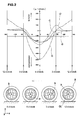
- Fig.2 shows exemplary variations of strain of a vehicle wheel which is rolling under the following conditions (1), (2), (3) and (4) where various forces F are exerted on the wheel axis CL.
- Condition line Wheel force F Vertical force Fx(kgf) Lateral force Fy(kgf) Longitudinal force (kgf) Torque Fx(kgf ⁇ m) around x-axis 1) continuous line 500 0 0 0 2) dashed line 500 400 0 0 3) broken line 500 0 400 0 4) double-dashed line 500 0 0 5
- the strain was measured at a fixed position on the wheel disk (radius part) 2b2 as a tensile strain (-) or compressive strain (+) in the radial direction.
- the test tire used was a pneumatic radial tire of size 195/60R15 for passenger cars.
- the wheel was that of an aluminum alloy having a rim size of 6JJX15.
- the tire inflation pressure was 200 kPa.
- the vertical force Fx means a force in the vertical direction (x-direction).
- the vertical force Fx is mainly its share of the vehicle weight and the reactive force from the ground.
- the lateral force Fy means a force in the lateral direction (y-direction).
- the lateral force Fy (side force) includes a cornering force.
- the longitudinal force Fz means a force in the back and forth direction (z-direction).
- the longitudinal force Fz may include a breaking force and accelerating force.
- the torque Ft means a force around a vertical axis perpendicular to the wheel axis CL (or around x-axis).
- the torque Ft may include a self-aligning torque and steer torque.
- the xyz directions are referred to in the orthogonal coordinate system fixed to the wheel as shown in Fig.3.
- the compressive strain (-) occurs and becomes maximum at the six-o'clock position P1.
- the strain under the condition (2) (dashed line) becomes maximum in the four conditions.
- the strain shows a maximum towards the tensile side whereas it does not show any maximum at the other position.
- the strain largely inclines towards the tensile side at the three-o'clock position as shown in Fig.2.
- the strain S varies depending on both the measuring position P and combination of various forces F exerted on the vehicle wheel 2.
- the strain S occurring on a wheel has sensibilities to the respective wheel forces F and the sensibilities vary depending on the measuring position P, and the variations (curves in Fig.2) are generally different from each other as explained above.
- the strain S at a certain position on the wheel disk is the summation of the strains caused by the respective wheel forces.
- the wheel forces can be obtained by solving simultaneous equations prepared in advance through measurements of the parameters at the above-mentioned predetermined positions P.
- the wheel force F can be obtained by computing equations, for example the following determinant.
- A1 ⁇ sa(500, 0, 0, 0) -Sa(0, 0, 0, 0) ⁇ /500
- A2 ⁇ Sa(500, 400, 0, 0)-Sa(500, 0, 0, 0) ⁇ /400
- A3 ⁇ Sa(500, 0, 400, 0)-Sa(500, 0, 0, 0) ⁇ /400
- A4 ⁇ Sa(500, 0, 0, 5) -Sa(500, 0, 0, 0) ⁇ /5
- B1 ⁇ Sb(500, 0, 0, 0) -Sb(0, 0, 0, 0) ⁇ /500
- B2 ⁇ Sb(500, 400, 0, 0)-Sb(500, 0, 0, 0) ⁇ /400
- B3 ⁇ Sb(500, 0, 400, 0)-Sb(500, 0, 0, 0) ⁇ /400
- B4 ⁇ Sb(500, 0, 0, 5) -Sb(
- the strain Sa(500, 0, 0, 0) is measured. Further, by applying lateral force Fy of 400 kgf together with vertical force Fx of 500 kgf, the strain Sa(500, 400, 0, 0) is measured. Furthermore, by applying vertical force Fx of 500 kgf and torque Ft of 5 kgf ⁇ m, the strain Sa(500, 0, 0, 5) is measured. Then, by making the above calculation, the coefficients A1-A4 are obtained. As to the remaining three groups, in the same way as above excepting the measuring positions P, the strains are measured and by making the calculation, the coefficients B1-B4, C1-C4 and D1-D4 can be obtained.
- the number of the measuring position may be reduced to only one (three-o'clock position), but in order to promote accuracy, two or more positions are desired.
- various detectors or sensors of mechanical type, semiconductor type etc. may be used.
- a strain gauge of wire resistance type is used. But it is of course possible to use another type of sensor depending on the kind of the parameter and the environment.
- the device for determining the wheel force according to the present invention must be able to determine the physical parameters (strain S) of the rolling wheel 2b while the vehicle is traveling.
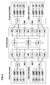
- Fig.4 is a block diagram showing an example of the device which can output electronic data on all of the above-mentioned wheel forces on each wheel of a four-wheeled vehicle in order to, for example, provide: data on the longitudinal force Fz, especially, breaking force for the undermentioned brake system BS; data on the torque Ft for a steering system such as a steer-by-wire system SW which requires feedback when the driver turns the steering wheel; and data on the vertical force Fx and lateral force Fy for a suspension control system and attitude control system.
- data on the longitudinal force Fz especially, breaking force for the undermentioned brake system BS
- data on the torque Ft for a steering system such as a steer-by-wire system SW which requires feedback when the driver turns the steering wheel
- data on the vertical force Fx and lateral force Fy for a suspension control system and attitude control system.
- strain gauge sensors 3A, 3B, 3C and 3D are provided on the wheel disk 2b2 every 90 degrees around the rotational axis CL of the wheel 2b under the same conditions, e.g. at the same distance C from the rotational axis as shown in Fig.1. This is because the strain S can be measured at four positions P1-P4 without time lag. But, in case of a system which permits a slight time lag, the use of less sensors or only one sensor 3 may be possible because the sensor 3 can measure the force F at every position P while moving around the rotational axis CL.
- wireless transmission system is employed between the vehicle wheels 2 and the vehicle body, which comprises a transmitter TR on each wheel 2b and a receiver RE disposed on the vehicle body.
- the transmission system may utilize radio waves, lightwave or electromagnetic induction.
- the rim 2b1 is not preferable because the strain is liable to vary widely by other factors than wheel force, for example, tire inflation pressure, road surface conditions, tire engaging force and the like, and it is very difficult to discriminate the wheel forces.
- the wheel disk 2b2 is generally easy to discriminate the wheel forces as explained above, but, in order to minimize the adverse effects of the relatively large rim deformation, a position in the direction of the hub or in the middle is generally preferred rather than the near rim position on the radius part 2b2.
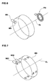
- Fig.6 shows an example of the detector part of the sensor-locating device TG.
- the detector part comprises a magnetic material MG fixed to each wheel, a magnetic sensor MS provided on the vehicle body, and a pulse generator PG.
- the magnetic material MG and magnetic sensor MS constitute a part of a trigger device.
- the trigger device outputs a trigger signal when the magnetic material MG gets near to the magnetic sensor MS.
- the magnetic material MG is one piece of magnet, and the trigger signal is outputted once per one revolution of the wheel.
- the pulse generator PG outputs a pulse every predetermined rotational angle of the wheel.
- the pulse generator PG is a combination of a rotor provided with teeth at even intervals and disposed on the vehicle axle to rotate together with the vehicle wheel, and a generator outputting one pulse corresponding to each tooth detected.
- the wheel has rotated 90 degrees.
- the magnetic sensor MS and magnetic material MG are arranged such that, when the sensors 3A-3D are at the measuring positions P, namely, the above-mentioned three, six, nine and twelve-o'clock positions P1-P4, a trigger signal is generated.
- the sensor 3A is at the six-o'clock position P1, the sensor 3B is at the nine-o'clock position P2, the sensor 3C is at the twelve-o'clock position P3 and the sensor 3D is at the three-o'clock position P4 as shown in Fig.1. Accordingly, when 12 pulses are counted, 3A is at P2, 3B at P3, 3C at P4 and 3D at P1. When 24 pulses are counted, 3A is at P3, 3B at P4, 3C at P1 and 3D at P2. When 36 pulses are counted, 3A is at P4, 3B at P1, 3C at P2 and 3D at P3.
- a combination of the single magnetic material MS and a plurality of magnetic sensors MS disposed on the vehicle body is also possible.
- the sensors 3 can be easily located without counting the pulses thus without using the pulse generator and counter.
- the analog output of the sensor 3 is usually very small. Therefore, a linear amplifier AMP is used. But if the sensor output is nonlinear, a nonlinear or equalizer amplifier AMP is preferably used. if necessary, an analog to digital converter may be included in the amplifier AMP.
- the outputs from the amplifiers AMP of the respective sensors 3A-3D are encoded/modulated and send out by the transmitter TR.
- the transmitted signal is received and decoded/demodulated by the receiver RE, and outputted towards the controller CON comprising a CPU, memory, I/O device and the like.
- the amplifier AMP and transmitter TR is fixed to the wheel, but it may be also possible to fix to another part as far as the part rotates together with the wheel such as a braking mechanism or near part.
- the controller CON In case of the construction shown in Fig.4 and the above-mentioned magnetic material MG and sensor MS arrangement, the following processes are carried out by the controller CON with respect to each wheel if the traveling direction is forward. If reverse, similar processes or other processes may be carried out. Incidentally, the controller CON can get the data on the traveling direction from a switch connected with the transmission selector or the like.
- the controller CON waits for a trigger signal; if a trigger signal is detected, starts to count pulses; and the same time, checks if the count number reaches to the preset numbers (in this example, 12, 24, 36 and 48); if not, continues to count the pulses; if the count number is one of the preset numbers, locates the sensors by using the count number as explained above; and at the same time, checks if the count number is the maximum preset number (48), if so, resets the pulse counter to zero; after the sensors are located, fetches data on the strain at each measuring position from the sensor through the transmission system; and then computes the wheel forces by using the strain data and information such as the above-mentioned equations or determinant which has been acquired from the measurement of the wheel in advance and stored on the memory; and outputs electronic data of the required wheel force (in this example, all of the above-mentioned vertical force Fx
- the existing anti lock brake system monitors the rotation of the wheel during braking, and controls the braking mechanism not to lock the wheel by reducing the force restraining the rotation of the wheel if wheel lock is detected.
- the frictional force becomes considerably decreased.
- a controller monitors the longitudinal force Fz (breaking force) during braking, and controls the braking mechanism BK so that the breaking force (frictional force) becomes maximum by reducing or increasing the force restraining the rotation of the wheel.
- Fz breaking force
- BK braking mechanism
- a reactive force corresponding to or proportional to the torque Ft is applied to the steering wheel of the vehicle as feedback by using a torque generator such as electric motor. Therefore, the driver's feel is remarkably improved.
- Fig.7 shows another example of the detector part of the sensor-locating device TG which can locate the sensors 3 without counting the pulses from the pulse generator PG.
- the detector part comprises the magnetic material MS made up of a plurality of magnets, and a plurality of magnetic sensors MS1 and MS2.
- the magnets are grouped such that each group has a unique arrangement of the north pole (N) and south pole (S) so as to be able to identify the group by detecting the NS pole arrangement.
- NS pole arrangement in case the group number is four and the pole number in each group is two Group(Position) NS pole arrangement 1 N + N 2 S + N 3 N + S 4 S + S
- this concept can be applied to not only magnetism but also other physical properties as far as sensible by appropriate sensing devices.
- the electric power for the transmitter TR, amplifiers AMP, sensors 3 and so forth provided on the vehicle wheel may be supplied through a wireless system utilizing, for example, electromagnetic induction. But, in this example, the electric power is supplied through a power transmission unit utilizing physical contact between electric conductors such as slip ring unit. In this case, it is possible to use the physical contact type power transmission unit in order to send the sensor data from the wheels to the vehicle body. More specifically, the transmitter TR generates a carrier wave modulated by the sensor data and superposes the modulated carrier wave on the DC power. The modulated carrier wave is split off from the DC power and demodulated into the sensor data by the receiver RE.
Landscapes
- Engineering & Computer Science (AREA)
- Chemical & Material Sciences (AREA)
- Physics & Mathematics (AREA)
- Mechanical Engineering (AREA)
- General Physics & Mathematics (AREA)
- Metallurgy (AREA)
- Thermal Sciences (AREA)
- Crystallography & Structural Chemistry (AREA)
- Materials Engineering (AREA)
- Organic Chemistry (AREA)
- Automation & Control Theory (AREA)
- Transportation (AREA)
- Force Measurement Appropriate To Specific Purposes (AREA)
Applications Claiming Priority (4)
| Application Number | Priority Date | Filing Date | Title |
|---|---|---|---|
| JP2002352854 | 2002-12-04 | ||
| JP2002321416 | 2002-12-04 | ||
| JP2003127337A JP2004233331A (ja) | 2002-12-04 | 2003-05-02 | 車輪力検出装置及び車輪力検出方法 |
| JP2003127337 | 2003-05-02 |
Publications (1)
| Publication Number | Publication Date |
|---|---|
| EP1426259A1 true EP1426259A1 (fr) | 2004-06-09 |
Family
ID=32964411
Family Applications (1)
| Application Number | Title | Priority Date | Filing Date |
|---|---|---|---|
| EP03027746A Withdrawn EP1426259A1 (fr) | 2002-12-04 | 2003-12-02 | Procédé et dispositif pour déterminer la force de roue |
Country Status (3)
| Country | Link |
|---|---|
| US (1) | US7418362B2 (fr) |
| EP (1) | EP1426259A1 (fr) |
| JP (1) | JP2004233331A (fr) |
Cited By (8)
| Publication number | Priority date | Publication date | Assignee | Title |
|---|---|---|---|---|
| WO2006128878A1 (fr) * | 2005-05-30 | 2006-12-07 | Interfleet Technology Ab | Procede et systeme permettant de determiner une pluralite de composantes de charge s'exerçant sur une roue |
| FR2894669A1 (fr) * | 2005-12-08 | 2007-06-15 | Peugeot Citroen Automobiles Sa | Methode d'estimation en temps reel d'un effort et d'un effort arriere appliques par le sol a un vehicule |
| FR2924660A1 (fr) * | 2007-12-05 | 2009-06-12 | Renault Sas | Dispositif et procede de freinage avec capteur d'efforts |
| CN103076131A (zh) * | 2012-12-31 | 2013-05-01 | 东南大学 | 用于测量大型机械臂大力与小力矩的六维力与力矩传感器 |
| CN103837121A (zh) * | 2012-11-27 | 2014-06-04 | 韩国轮胎株式会社 | 使用4个力传感器的锥度测定系统以及方法 |
| ES2566048A1 (es) * | 2016-01-15 | 2016-04-08 | Universidad Politécnica de Madrid | Método de medición de esfuerzos generados en el contacto entre el neumático y la calzada mediante la instrumentación de la llanta |
| IT201800003697A1 (it) * | 2018-03-16 | 2019-09-16 | Milano Politecnico | Cerchio con sensore e ruota comprendente tale cerchio |
| AT524837A4 (de) * | 2021-07-07 | 2022-10-15 | Avl List Gmbh | System aus messsystem und felge |
Families Citing this family (20)
| Publication number | Priority date | Publication date | Assignee | Title |
|---|---|---|---|---|
| JP4844020B2 (ja) * | 2005-06-20 | 2011-12-21 | 日産自動車株式会社 | ホイールの分力計測装置 |
| JP4914179B2 (ja) * | 2006-11-07 | 2012-04-11 | 住友ゴム工業株式会社 | 空気入りタイヤ、及びそれに作用する力の検出方法 |
| JP5034666B2 (ja) * | 2007-02-22 | 2012-09-26 | 住友金属工業株式会社 | 鉄道車両の車輪とレール間に作用する接線力の測定方法 |
| GB2462305B (en) * | 2008-08-01 | 2013-05-15 | Haldex Brake Products Ltd | Method of monitoring a vehicle and apparatus therefor |
| JP5286027B2 (ja) | 2008-10-28 | 2013-09-11 | 株式会社アドヴィックス | 車両安定化制御装置 |
| US9139173B2 (en) | 2008-10-28 | 2015-09-22 | Advics Co., Ltd. | Device for controlling traveling of vehicle |
| ES2363400B2 (es) | 2011-03-03 | 2011-12-20 | Universidad Politécnica de Madrid | Método y sistema de estimación de los esfuerzos generados por el contacto del neumático con la calzada en una llanta instrumentalizada. |
| CN103344382A (zh) * | 2013-07-09 | 2013-10-09 | 浙江省计量科学研究院 | 滚筒反力式汽车制动检验台动态制动力两轮检定仪 |
| US9068878B2 (en) * | 2013-08-23 | 2015-06-30 | Trimble Navigation Limited | Vehicle weight sensor based on wheel rim strain measurements |
| CN106872084B (zh) * | 2017-02-15 | 2019-03-22 | 清华大学 | 一种汽车行驶时单轮自回正力矩测量装置和方法 |
| US10481142B2 (en) * | 2017-05-25 | 2019-11-19 | Deere & Company | Sensor system for determining soil characteristics |
| US10894533B2 (en) | 2017-12-22 | 2021-01-19 | Robert Bosch Gmbh | Wheel torque sensor for highly automated driving vehicles |
| US10807420B2 (en) | 2018-03-20 | 2020-10-20 | Robert Bosch Gmbh | Dual tire pressure monitor and wheel torque sensor for vehicles |
| DE102018221103A1 (de) * | 2018-12-06 | 2020-06-10 | Continental Automotive Gmbh | Anordnung und Verfahren zum Bestimmen eines Fahrzeuggewichts |
| US10969292B2 (en) * | 2019-08-30 | 2021-04-06 | Balanced Engineering Solution, Llc | Apparatus for measuring imbalance forces of a tire/hub assembly of a vehicle during motion of the vehicle |
| EP4069530B1 (fr) * | 2019-12-06 | 2026-03-25 | Camso Inc. | Systèmes et procédés de surveillance d'ensembles roues |
| KR20210121657A (ko) * | 2020-03-31 | 2021-10-08 | 현대자동차주식회사 | 차량용 노면입력 하중 측정 시스템 및 방법 |
| US11731673B1 (en) | 2022-09-26 | 2023-08-22 | Balanced Engineering Solution, Llc | Wheel-mounted sensor ring apparatus for determining anomalies associated with a railcar wheelset, or a railcar bogie assembly that the railcar wheelset is part of, or a track |
| JP2024130892A (ja) * | 2023-03-15 | 2024-09-30 | Toyo Tire株式会社 | タイヤ組立体およびタイヤ力推定システム |
| CN117022360A (zh) * | 2023-08-07 | 2023-11-10 | 中车青岛四方机车车辆股份有限公司 | 一种动力学性能在线监测转向架及轨道车辆 |
Citations (7)
| Publication number | Priority date | Publication date | Assignee | Title |
|---|---|---|---|---|
| US4748844A (en) * | 1986-05-09 | 1988-06-07 | Yamato Scale Company, Limited | Device for measuring components of force and moment applied to vehicle tire |
| US5313828A (en) * | 1991-10-09 | 1994-05-24 | Mercedes-Benz Ag | Multi-component measuring disc wheel |
| DE4435160A1 (de) * | 1994-09-30 | 1996-04-04 | Continental Ag | Einrichtung zur Ermittlung der Umfangskraft eines Fahrzeugrades |
| DE19548759A1 (de) * | 1995-12-23 | 1997-06-26 | Continental Ag | Einrichtung und Verfahren zum Messen und zum Ermitteln von Radlast, Beschleunigungskraft und von der Geschwindigkeit eines Fahrzeugs |
| US5894094A (en) * | 1996-07-06 | 1999-04-13 | Bayerische-Motoren Werke Aktiengesellschaft | Wheel force measuring hub assembly |
| DE10001272A1 (de) * | 2000-01-14 | 2001-07-26 | Daimler Chrysler Ag | Einrichtung und Verfahren zur Ermittlung von Kräften im Reifen eines Fahrzeugrades |
| EP1225451A1 (fr) * | 2001-01-20 | 2002-07-24 | Robert Bosch Gmbh | Dispositif de mesure dans le roulement de roue d'un véhicule à moteur pour déterminer des forces et des moments |
Family Cites Families (19)
| Publication number | Priority date | Publication date | Assignee | Title |
|---|---|---|---|---|
| US4171641A (en) * | 1978-07-13 | 1979-10-23 | The B. F. Goodrich Company | Method for measuring uniformity of tires |
| EP0363570B1 (fr) * | 1988-10-13 | 1996-02-21 | Japan Electronics Industry, Ltd. | Détecteur de friction de surface de route et détecteur de coefficient de friction de surface de route et dispositif de freinage à antiblocage de véhicule |
| US6032520A (en) * | 1990-03-19 | 2000-03-07 | Japan Electronics Industry, Limited | Device for measuring action force of wheel and device for measuring stress of structure |
| US5492002A (en) * | 1993-08-23 | 1996-02-20 | Higgins; Richard L. | Instrumented wheelset system |
| FR2719667B1 (fr) * | 1994-05-04 | 1996-07-26 | Laurent Pneu | Procédé et dispositif de contrôle électromagnétique de pneumatiques usagés. |
| US6122585A (en) * | 1996-08-20 | 2000-09-19 | Kabushiki Kaisha Toyota Chuo Kenkyusho | Anti-lock braking system based on an estimated gradient of friction torque, method of determining a starting point for anti-lock brake control, and wheel-behavior-quantity servo control means equipped with limit determination means |
| DE19646251C2 (de) * | 1996-11-08 | 1998-11-12 | Continental Ag | Luftreifen mit Mitteln zur Beschaffung von Informationen, seine Verwendung und Vorrichtung zu seiner Herstellung |
| US6038933A (en) * | 1997-07-15 | 2000-03-21 | Mts Systems Corporation | Multi-axis load cell |
| US6324919B1 (en) * | 1998-02-04 | 2001-12-04 | Michigan Scientific Corporation | Multi-axis wheel load transducer |
| US6308758B1 (en) * | 1999-07-06 | 2001-10-30 | Continental Ag | Elastomeric tire having magnetized sidewall and method of manufacturing same |
| JP2001047822A (ja) * | 1999-08-10 | 2001-02-20 | Toyo Tire & Rubber Co Ltd | 転動タイヤの摩擦エネルギー解析方法 |
| DE10013965A1 (de) * | 2000-03-21 | 2001-10-11 | Hayes Lemmerz Holding Gmbh | Regelverfahren für einen zweiaxialen Räderprüfstand zur Simulation von Fahrbelastungen und zweiaxialer Räderprüfstand |
| JP3655172B2 (ja) * | 2000-06-22 | 2005-06-02 | 光洋精工株式会社 | 車両用制動装置 |
| US6595045B1 (en) * | 2000-10-16 | 2003-07-22 | Veridian Engineering, Inc. | Vehicular sensors |
| DE10164929B4 (de) * | 2001-02-02 | 2010-08-19 | Schaeffler Technologies Gmbh & Co. Kg | Verfahren zum Erfassen von Reaktionskräften in einem Radlager |
| JP4779246B2 (ja) * | 2001-06-28 | 2011-09-28 | トヨタ自動車株式会社 | タイヤ作用力検出装置 |
| JP4090726B2 (ja) * | 2001-11-26 | 2008-05-28 | 横浜ゴム株式会社 | ブレーキ制御装置、ブレーキ制御方法および記録媒体 |
| JP4255048B2 (ja) * | 2002-08-02 | 2009-04-15 | 横浜ゴム株式会社 | タイヤの歪み状態検出方法、歪み状態検出装置及びそのセンサユニット並びにこれを備えたタイヤ |
| US7249498B2 (en) * | 2003-10-27 | 2007-07-31 | Sumitomo Rubber Industries, Ltd. | System and method for determining tire force |
-
2003
- 2003-05-02 JP JP2003127337A patent/JP2004233331A/ja active Pending
- 2003-12-02 EP EP03027746A patent/EP1426259A1/fr not_active Withdrawn
- 2003-12-03 US US10/725,459 patent/US7418362B2/en not_active Expired - Fee Related
Patent Citations (7)
| Publication number | Priority date | Publication date | Assignee | Title |
|---|---|---|---|---|
| US4748844A (en) * | 1986-05-09 | 1988-06-07 | Yamato Scale Company, Limited | Device for measuring components of force and moment applied to vehicle tire |
| US5313828A (en) * | 1991-10-09 | 1994-05-24 | Mercedes-Benz Ag | Multi-component measuring disc wheel |
| DE4435160A1 (de) * | 1994-09-30 | 1996-04-04 | Continental Ag | Einrichtung zur Ermittlung der Umfangskraft eines Fahrzeugrades |
| DE19548759A1 (de) * | 1995-12-23 | 1997-06-26 | Continental Ag | Einrichtung und Verfahren zum Messen und zum Ermitteln von Radlast, Beschleunigungskraft und von der Geschwindigkeit eines Fahrzeugs |
| US5894094A (en) * | 1996-07-06 | 1999-04-13 | Bayerische-Motoren Werke Aktiengesellschaft | Wheel force measuring hub assembly |
| DE10001272A1 (de) * | 2000-01-14 | 2001-07-26 | Daimler Chrysler Ag | Einrichtung und Verfahren zur Ermittlung von Kräften im Reifen eines Fahrzeugrades |
| EP1225451A1 (fr) * | 2001-01-20 | 2002-07-24 | Robert Bosch Gmbh | Dispositif de mesure dans le roulement de roue d'un véhicule à moteur pour déterminer des forces et des moments |
Non-Patent Citations (1)
| Title |
|---|
| OTTER D E ET AL: "A design for next generation load measuring wheel sets", PROCEEDINGS OF THE IEEE/ASME JOINT RAILROAD CONFERENCE. ST. LOUIS, MAY 21 - 23, 1991, NEW YORK, IEEE, US, 21 May 1991 (1991-05-21), pages 37 - 42, XP010047397, ISBN: 0-7803-0072-6 * |
Cited By (17)
| Publication number | Priority date | Publication date | Assignee | Title |
|---|---|---|---|---|
| EP2141473A1 (fr) * | 2005-05-30 | 2010-01-06 | Interfleet Technology AB | Procédé et système permettant de déterminer une pluralité de composantes de charge s'exerçant sur une roue |
| US7926362B2 (en) | 2005-05-30 | 2011-04-19 | Interfleet Technology Ab | Method and a system for determining a plurality of load components on a wheel |
| WO2006128878A1 (fr) * | 2005-05-30 | 2006-12-07 | Interfleet Technology Ab | Procede et systeme permettant de determiner une pluralite de composantes de charge s'exerçant sur une roue |
| FR2894669A1 (fr) * | 2005-12-08 | 2007-06-15 | Peugeot Citroen Automobiles Sa | Methode d'estimation en temps reel d'un effort et d'un effort arriere appliques par le sol a un vehicule |
| EP1804041A1 (fr) * | 2005-12-08 | 2007-07-04 | Peugeot Citroën Automobiles Sa | Méthode d'estimation en temps réel d'un effort avant et d'un effort arrière appliqués par le sol à un véhicule |
| FR2924660A1 (fr) * | 2007-12-05 | 2009-06-12 | Renault Sas | Dispositif et procede de freinage avec capteur d'efforts |
| CN103837121B (zh) * | 2012-11-27 | 2017-04-12 | 韩国轮胎株式会社 | 使用4个力传感器的锥度测定系统以及方法 |
| CN103837121A (zh) * | 2012-11-27 | 2014-06-04 | 韩国轮胎株式会社 | 使用4个力传感器的锥度测定系统以及方法 |
| CN103076131A (zh) * | 2012-12-31 | 2013-05-01 | 东南大学 | 用于测量大型机械臂大力与小力矩的六维力与力矩传感器 |
| ES2566048A1 (es) * | 2016-01-15 | 2016-04-08 | Universidad Politécnica de Madrid | Método de medición de esfuerzos generados en el contacto entre el neumático y la calzada mediante la instrumentación de la llanta |
| WO2017121917A1 (fr) * | 2016-01-15 | 2017-07-20 | Universidad Politécnica de Madrid | Procédé de mesure d'efforts générés au niveau du contact entre le pneumatique et la chaussée par l'instrumentation de la jante |
| IT201800003697A1 (it) * | 2018-03-16 | 2019-09-16 | Milano Politecnico | Cerchio con sensore e ruota comprendente tale cerchio |
| WO2019175833A1 (fr) * | 2018-03-16 | 2019-09-19 | Politecnico Di Milano | Jante de roue comprenant un capteur et roue comprenant ladite jante |
| US11701928B2 (en) | 2018-03-16 | 2023-07-18 | Politecnico Di Milano | Rim for wheel with sensor and wheel comprising said rim |
| AT524837A4 (de) * | 2021-07-07 | 2022-10-15 | Avl List Gmbh | System aus messsystem und felge |
| AT524837B1 (de) * | 2021-07-07 | 2022-10-15 | Avl List Gmbh | System aus messsystem und felge |
| WO2023279129A1 (fr) * | 2021-07-07 | 2023-01-12 | Avl List Gmbh | Système composé d'un système de mesure et d'une jante |
Also Published As
| Publication number | Publication date |
|---|---|
| US20040162680A1 (en) | 2004-08-19 |
| JP2004233331A (ja) | 2004-08-19 |
| US7418362B2 (en) | 2008-08-26 |
Similar Documents
| Publication | Publication Date | Title |
|---|---|---|
| US7418362B2 (en) | Method and device for determining wheel force | |
| CN101932458B (zh) | 用于确定车辆轮胎花纹深度的方法 | |
| JP4847444B2 (ja) | 4つの歪みゲージを有する変形検知ベアリング | |
| US8096174B2 (en) | Vehicle load weight detecting apparatus | |
| CN101432155B (zh) | 用于车辆数据特别是轮式行走车辆的速度的测量装置 | |
| US10018524B2 (en) | Load determining system for a rolling element bearing | |
| EP1550813B1 (fr) | Unite de roulement a rouleaux avec capteur et unite de moyeu avec capteur | |
| GB2457357A (en) | Method of calibrating wheel speed | |
| EP3509875B1 (fr) | Estimation des rayons de roulis de roue absolu et estimation de la valeur de compression verticale | |
| JPWO2004018273A1 (ja) | 車両制御システム | |
| JPH10297228A (ja) | タイヤ空気圧警報装置 | |
| JP2004517337A (ja) | 特に自動車のホイール軸受けに配置された、物理的な測定量を検出するための装置 | |
| US11701928B2 (en) | Rim for wheel with sensor and wheel comprising said rim | |
| US20100030512A1 (en) | Determination and wireless communication of sensed vehicle data for computing vehicle speed | |
| JP2008216016A (ja) | 回転角度算出装置及び変位量算出装置 | |
| JP2001241945A (ja) | タイヤの状態検出装置、移動体制御装置、及びタイヤの状態検出方法 | |
| US6873925B2 (en) | Calculation method of strains applied between a rotating part and a bearing on which it rotates | |
| US7257997B2 (en) | Method of detecting longitudinal force of tire and longitudinal force detecting apparatus used therein | |
| JP2001191767A (ja) | タイヤの状態検出装置、自動車制御装置、及びタイヤの状態検出方法 | |
| JP3255043B2 (ja) | 車軸力検出装置 | |
| JPH03215726A (ja) | スピンドルによる路面摩擦力検出装置、垂直荷重検出装置及び路面摩擦係数検出装置 | |
| JP2003509665A (ja) | 自動車の走行動特性状態を検出および評価する方法 | |
| JPS645224Y2 (fr) | ||
| JP7370628B1 (ja) | 移動速度計測装置 | |
| JPH0643932B2 (ja) | 車軸動力計 |
Legal Events
| Date | Code | Title | Description |
|---|---|---|---|
| PUAI | Public reference made under article 153(3) epc to a published international application that has entered the european phase |
Free format text: ORIGINAL CODE: 0009012 |
|
| AK | Designated contracting states |
Kind code of ref document: A1 Designated state(s): AT BE BG CH CY CZ DE DK EE ES FI FR GB GR HU IE IT LI LU MC NL PT RO SE SI SK TR |
|
| AX | Request for extension of the european patent |
Extension state: AL LT LV MK |
|
| 17P | Request for examination filed |
Effective date: 20041020 |
|
| AKX | Designation fees paid |
Designated state(s): DE FR GB |
|
| 17Q | First examination report despatched |
Effective date: 20050524 |
|
| 17Q | First examination report despatched |
Effective date: 20050524 |
|
| STAA | Information on the status of an ep patent application or granted ep patent |
Free format text: STATUS: THE APPLICATION IS DEEMED TO BE WITHDRAWN |
|
| 18D | Application deemed to be withdrawn |
Effective date: 20100701 |